Page 254 of 4331

AT
N
O P
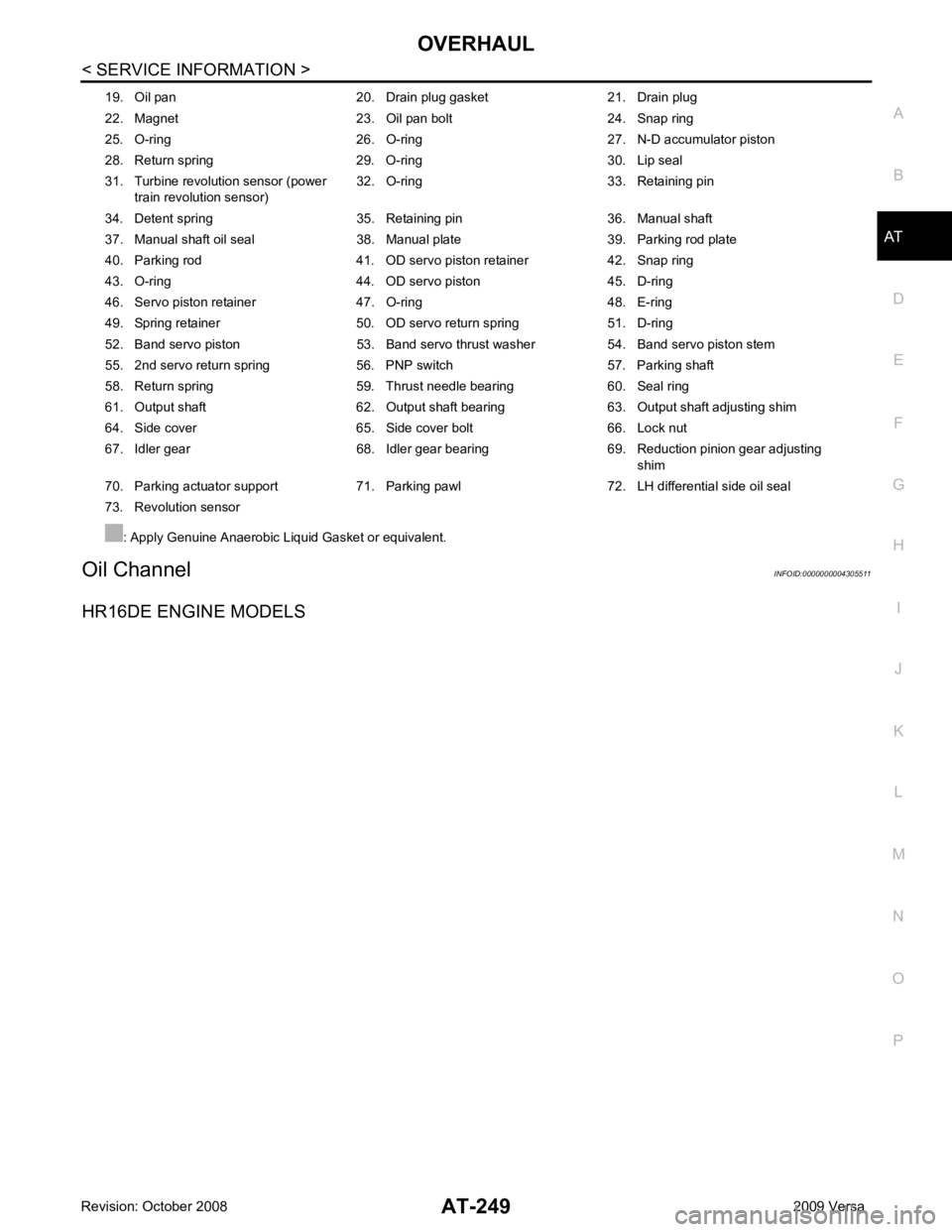
Oil Channel
INFOID:0000000004305511
HR16DE ENGINE MODELS 19. Oil pan 20. Drain plug gasket 21. Drain plug
22. Magnet 23. Oil pan bolt 24. Snap ring
25. O-ring 26. O-ring 27. N-D accumulator piston
28. Return spring 29. O-ring 30. Lip seal
31. Turbine revolution sensor (power train revolution sensor) 32. O-ring 33. Retaining pin
34. Detent spring 35. Retaining pin 36. Manual shaft
37. Manual shaft oil seal 38. Manual plate 39. Parking rod plate
40. Parking rod 41. OD servo piston retainer 42. Snap ring
43. O-ring 44. OD servo piston 45. D-ring
46. Servo piston retainer 47. O-ring 48. E-ring
49. Spring retainer 50. OD servo return spring 51. D-ring
52. Band servo piston 53. Band servo thrust washer 54. Band servo piston stem
55. 2nd servo return spring 56. PNP switch 57. Parking shaft
58. Return spring 59. Thrust needle bearing 60. Seal ring
61. Output shaft 62. Output shaft bearing 63. Output shaft adjusting shim
64. Side cover 65. Side cover bolt 66. Lock nut
67. Idler gear 68. Idler gear bearing 69. Reduction pinion gear adjusting shim
70. Parking actuator support 71. Parking pawl 72. LH differential side oil seal
73. Revolution sensor
: Apply Genuine Anaerobic Liquid Gasket or equivalent.
Page 266 of 4331
AT
N
O P
• HR16DE engine models
• MR18DE engine models
b. Remove bracket from converter housing
c. Remove converter housing by tapping it lightly.
d. Remove O-ring from differential lubricant hole.
24. Remove final drive assembly from transaxle case. SCIA7970E
SAT228F
Page 278 of 4331
AT
N
O P
46. Remove bearing retainer bolts, and then remove bearing
retainer (1) from transaxle case.
47. Remove return spring (2) from parking shaft (3) using a suitable tool.
(1): Parking pawl
• Inspect return spring (2), and replace if damaged or worn.
48. Draw out parking shaft (1), and then remove parking pawl (2) from transaxle case.
• Inspect parking shaft (1) and parking pawl (2), and replace
if damaged or worn.
49. Remove parking actuator support (1) from transaxle case. •Inspect parking actuator sup port (1), and replace if dam-
aged or worn.
50. Remove snap ring from transaxle case using a suitable tool.
51. Remove governor cap from transaxle case.
52. Remove O-ring from governor cap.
53. Remove LH differential side oil seal from transaxle case using a suitable tool.
CAUTION:
Be careful not to scratch transaxle case. ATM0076D
Page 344 of 4331
AT
N
O P
3. Remove speedometer drive gear from differential case.
4. Drive out lock pin from differential case (1) using Tool (A).
5. Draw out pinion mate shaft.
6. Remove pinion mate gears, pinion mate gear thrust washers, side gears and side gear thrust washers.
INSPECTION
Gears, Washers, Pinion Mate Shaft and Differential Case • Check mating surfaces of differential case, side gears, pinion mate gears and pinion mate shaft. Replace if necessary.
• Check washers for wear. Replace if necessary.
Bearings SAT316D
SAT544F
Page 345 of 4331

AT-340< SERVICE INFORMATION >
REPAIR FOR COMPONENT PARTS
• Make sure bearings roll freely and are free from noise, cracks, pit- ting or wear. Replace if necessary.
CAUTION:
When replacing taper roller b earing, replace outer and inner
race as a set.
ASSEMBLY
1. Attach side gear thrust washers to side gears, then install pinion mate thrust washers and pinion mate gears in place.
CAUTION:
Apply ATF to any parts.
2. Insert pinion mate shaft. CAUTION:
• When inserting, be careful not to damage pinion mate gear thrust washers.
• Apply ATF to pinion mate shaft.
3. Select side gear thrust washers according to the following procedures.
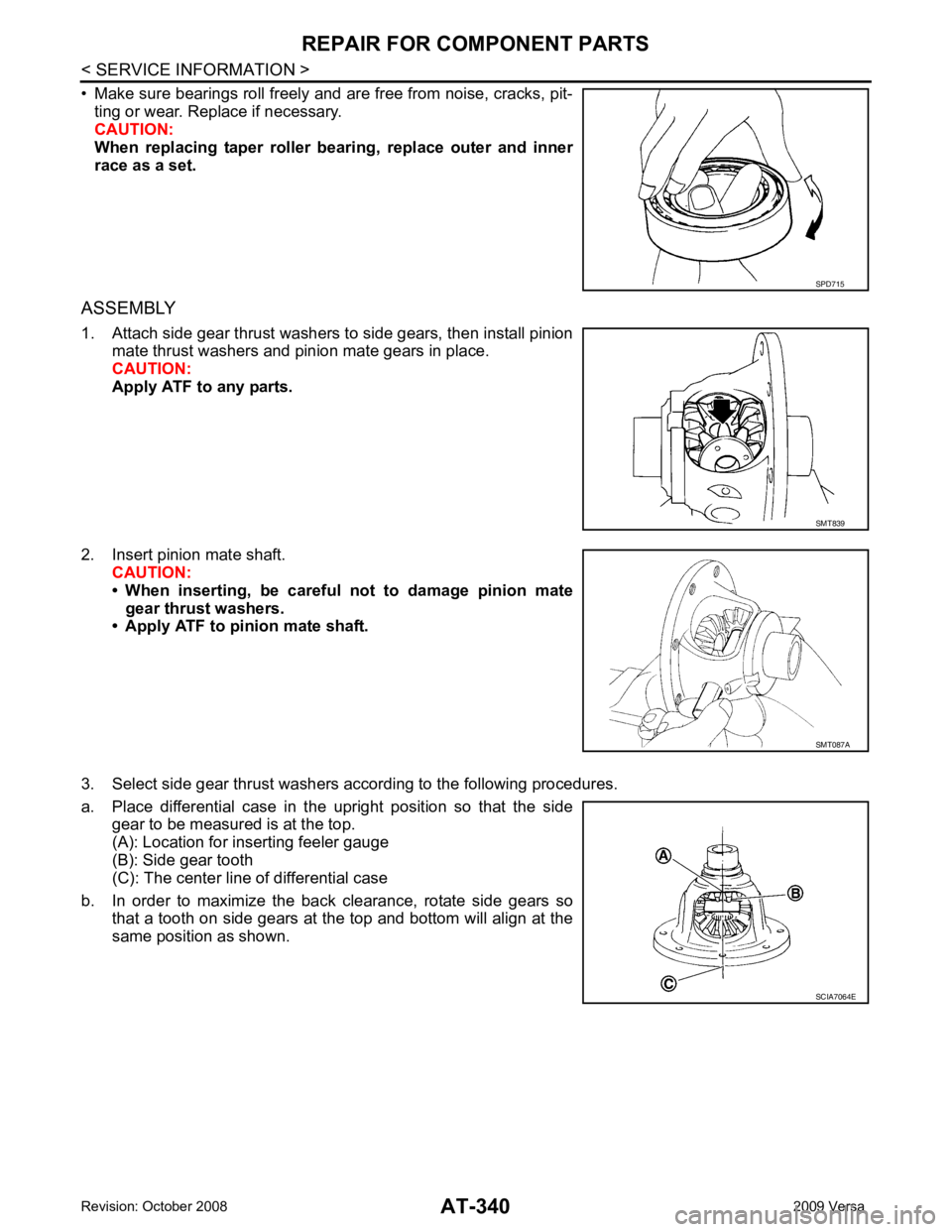
a. Place differential case in the upright position so that the side gear to be measured is at the top.
(A): Location for inserting feeler gauge
(B): Side gear tooth
(C): The center line of differential case
b. In order to maximize the back clearance, rotate side gears so that a tooth on side gears at the top and bottom will align at the
same position as shown. SPD715
SMT839
SMT087A
SCIA7064E
Page 346 of 4331

AT
N
O P
c. Adjust the back clearance of side
gear according to the following
procedures.
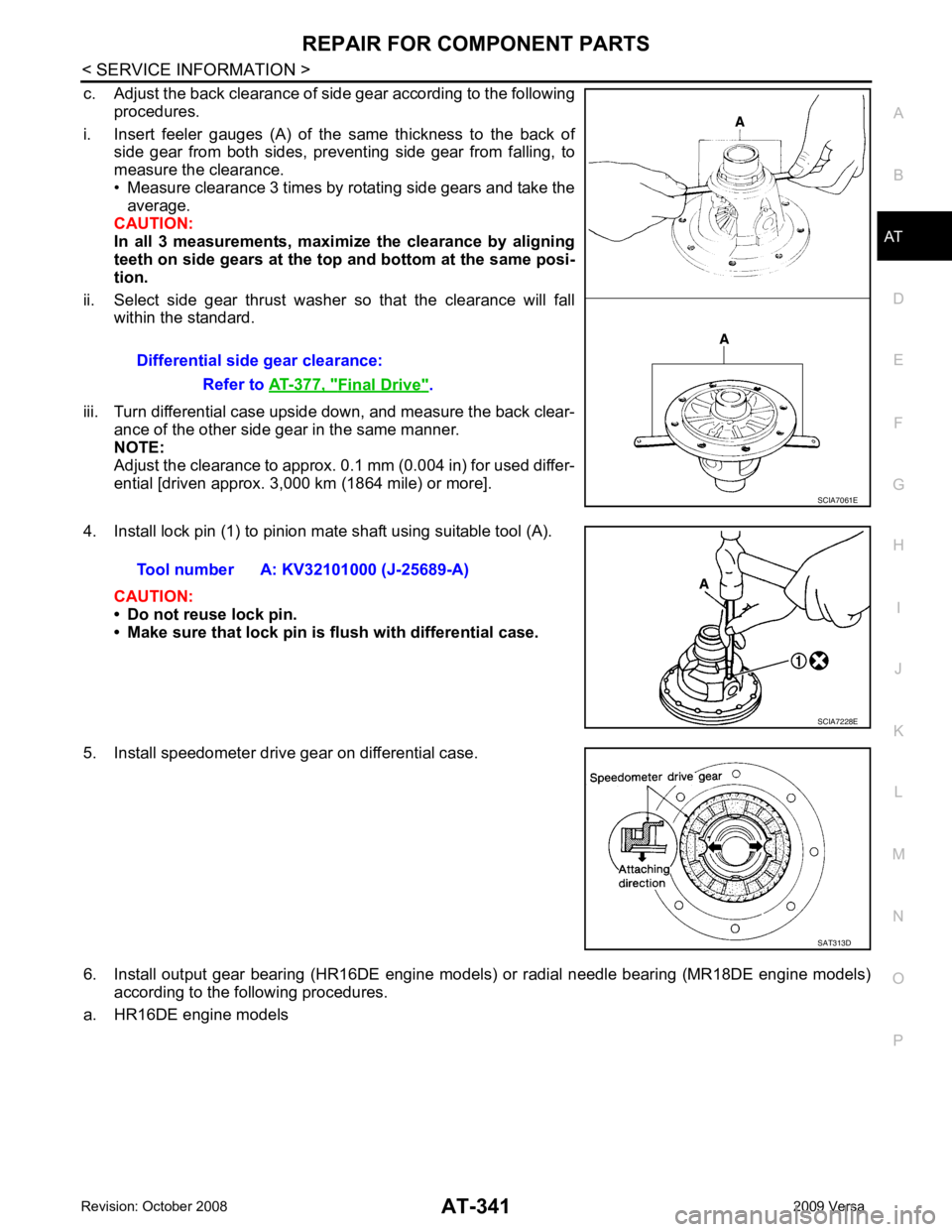
i. Insert feeler gauges (A) of the same thickness to the back of side gear from both sides, prevent ing side gear from falling, to
measure the clearance.
• Measure clearance 3 times by rotating side gears and take the
average.
CAUTION:
In all 3 measurements, maximi ze the clearance by aligning
teeth on side gears at the top and bottom at the same posi-
tion.
ii. Select side gear thrust washer so that the clearance will fall within the standard.
iii. Turn differential case upside down, and measure the back clear- ance of the other side gear in the same manner.
NOTE:
Adjust the clearance to approx. 0.1 mm (0.004 in) for used differ-
ential [driven approx. 3,000 km (1864 mile) or more].
4. Install lock pin (1) to pinion mate shaft using suitable tool (A).
CAUTION:
• Do not reuse lock pin.
• Make sure that lock pin is flush with differential case.
5. Install speedometer drive gear on differential case.
6. Install output gear bearing (HR16DE engine models) or radial needle bearing (MR18DE engine models) according to the following procedures.
a. HR16DE engine models Differential side gear clearance:
Refer to AT-377, " Final Drive " .
Page 348 of 4331

AT
N
O P
ASSEMBLY
Assembly (1) INFOID:0000000004305528
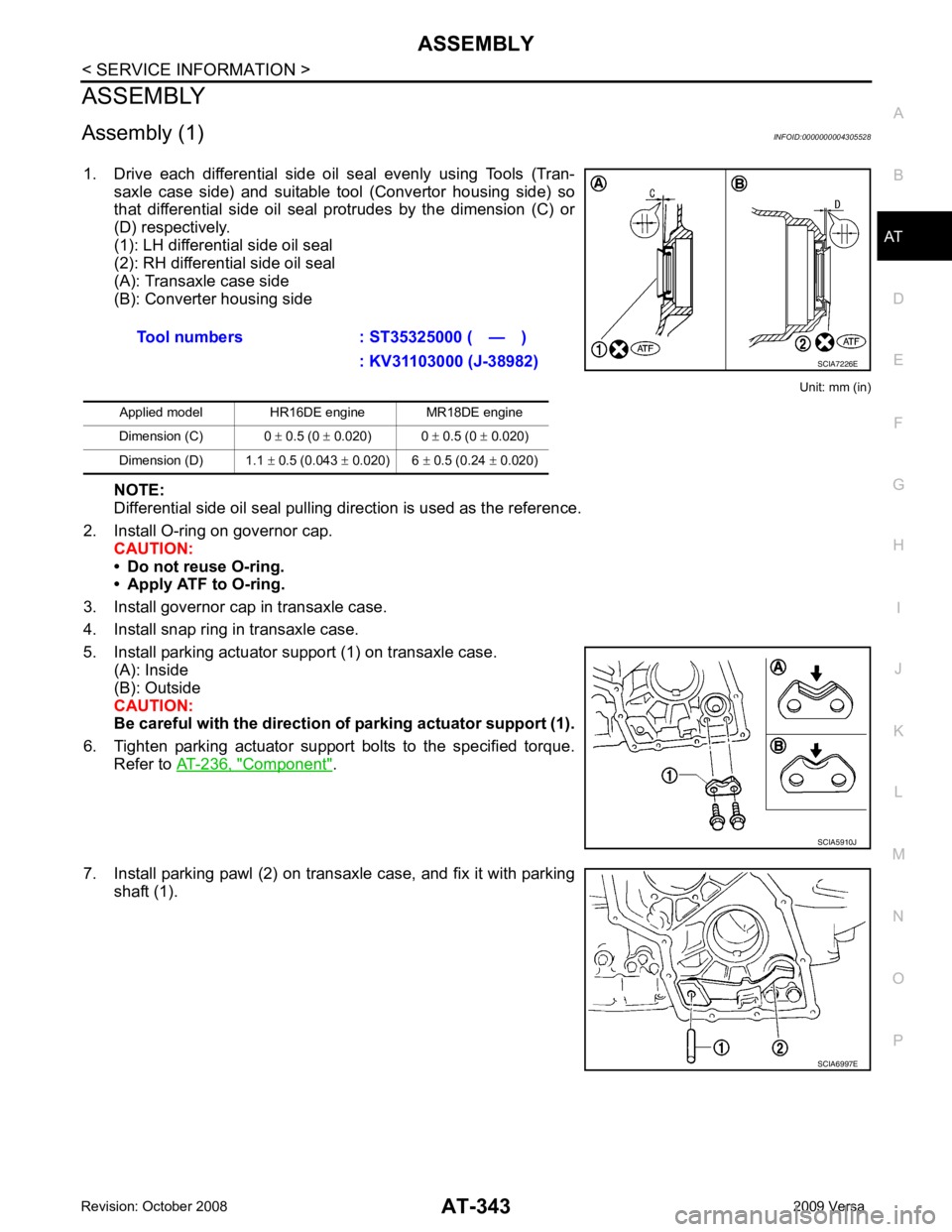
1. Drive each differential side oil seal evenly using Tools (Tran- saxle case side) and suitable tool (Convertor housing side) so
that differential side oil seal protrudes by the dimension (C) or
(D) respectively.
(1): LH differential side oil seal
(2): RH differential side oil seal
(A): Transaxle case side
(B): Converter housing side
Unit: mm (in)
NOTE:
Differential side oil seal pulling direction is used as the reference.
2. Install O-ring on governor cap. CAUTION:
• Do not reuse O-ring.
• Apply ATF to O-ring.
3. Install governor cap in transaxle case.
4. Install snap ring in transaxle case.
5. Install parking actuator support (1) on transaxle case. (A): Inside
(B): Outside
CAUTION:
Be careful with the direction of parking actuator support (1).
6. Tighten parking actuator support bolts to the specified torque. Refer to AT-236, " Component " .
7. Install parking pawl (2) on transaxle case, and fix it with parking shaft (1).Tool numbers : ST35325000 ( — )
: KV31103000 (J-38982)
Applied model HR16DE engine MR18DE engine
Dimension (C) 0 ± 0.5 (0 ± 0.020) 0 ± 0.5 (0 ± 0.020)
Dimension (D) 1.1 ± 0.5 (0.043 ± 0.020) 6 ± 0.5 (0.24 ± 0.020)
Page 353 of 4331
Component " .
13. After properly adjusting turning torque, clinch lock nuts (1) of idler gear and output gear as shown.
14. Install side cover gasket and side cover on transaxle case. CAUTION:
• Do not reuse side cover gasket.
• Completely remove all moisture, oil and old gasket, etc. from the transaxle case and side cover mating surfaces.
15. Tighten side cover bolts (1) to the specified torque. Refer to AT-236, " Component " .
Adjustment (1) (For MR18DE Engine Models) INFOID:0000000004305529
DIFFERENTIAL SIDE BEARING PRELOAD
1. Select proper thickness of differential side bearing adjusting shim using the following procedures. Tool number : ST27180001 (J-25726-A)
Output Shaft " .
SCIA6039J