Page 3392 of 4331
341, " Removal and Installation " (CVT),
AT-212, " Control Device
Removal and Installation " (A/T).
5. Pull up and disengage A/T and CVT console finisher metal clips (A/T and CVT only).
6. Remove A/T and CVT console finisher (A/T and CVT only).
7. Remove shift knob (M/T only). Refer to MT-90 .
8. Pull up and disengage M/T console boot metal clips (M/T only).
9. Remove M/T console boot (M/T only).
10. Disengage console rear finisher metal clips and pawl. : Metal clip
: Pawl
11. Remove console rear finisher.
12. Disengage console mask cover metal clips and pawls, and then remove console mask cover (with armrest).
: Metal clip
: Pawl PIIB2454J
PIIB6387E
Page 3395 of 4331
IP
N
O P
Disassembly
Remove the four screws, and then remove front cup holder from center console.
Assembly Assembly is in the reverse order of disassembly.
COMBINATION METER
Disassembly Disengage the eight tabs to separate front cover (1) from the unified
meter control unit assembly (2).
Assembly Assembly is in the reverse order of disassembly. 1. Center console 2. Front cup holder
LIIA2582E
Page 3396 of 4331

LAN
N
O P
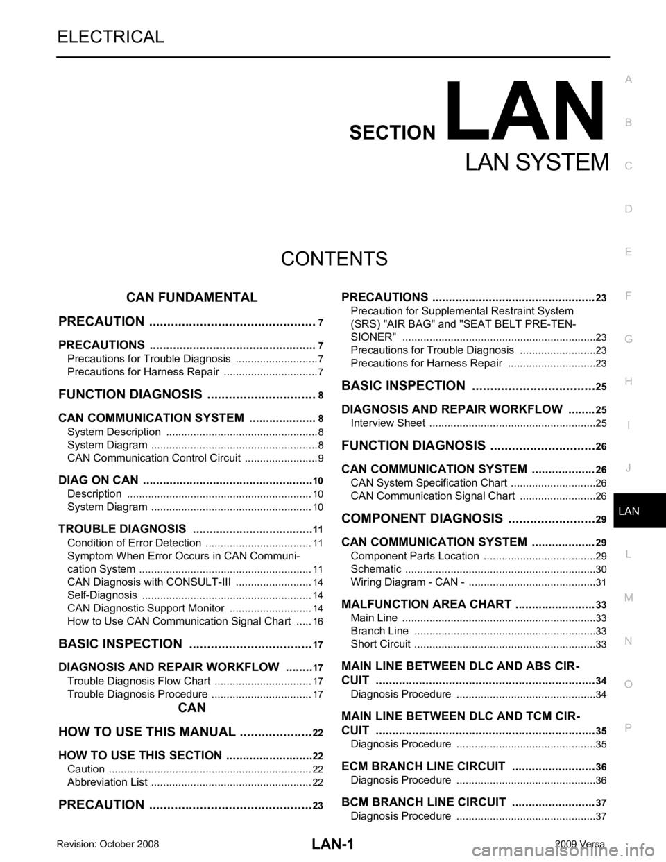
CONTENTS
LAN SYSTEM
CAN FUNDAMENTAL
PRECAUTION ....... ........................................
7
PRECAUTIONS .............................................. .....7
Precautions for Trouble Diagnosis ...................... ......7
Precautions for Harness Repair ................................7
FUNCTION DIAGNOSIS .. .............................8
CAN COMMUNICATION SYSTEM ................ .....8
System Description ............................................. ......8
System Diagram .................................................. ......8
CAN Communication Control Circuit ................... ......9
DIAG ON CAN ................................................ ....10
Description .......................................................... ....10
System Diagram .................................................. ....10
TROUBLE DIAGNOSIS ................................. ....11
Condition of Error Detection ................................ ....11
Symptom When Error Oc curs in CAN Communi-
cation System ...................................................... ....
11
CAN Diagnosis with CONSULT-III ...................... ....14
Self-Diagnosis ..................................................... ....14
CAN Diagnostic Support Monitor ........................ ....14
How to Use CAN Communication Signal Chart .. ....16
BASIC INSPECTION ....... ............................17
DIAGNOSIS AND REPAIR WORKFLOW ..... ....17
Trouble Diagnosis Flow Chart ............................. ....17
Trouble Diagnosis Procedure .............................. ....17
CAN
HOW TO USE THIS MANU AL .....................22
HOW TO USE THIS SECTION ....................... ....22
Caution ................................................................ ....22
Abbreviation List .................................................. ....22
PRECAUTION ....... .......................................23 PRECAUTIONS .................................................
23
Precaution for Supplemental Restraint System
(SRS) "AIR BAG" and "SEAT BELT PRE-TEN-
SIONER" ............................................................. ....
23
Precautions for Trouble Diagnosis ...................... ....23
Precautions for Harness Repair .......................... ....23
BASIC INSPECTION ....... ............................25
DIAGNOSIS AND REPAIR WORKFLOW ........ 25
Interview Sheet .................................................... ....25
FUNCTION DIAGNOSIS .. ............................26
CAN COMMUNICATION SYSTEM ................... 26
CAN System Specification Chart ......................... ....26
CAN Communication Signal Chart ...................... ....26
COMPONENT DIAGNOSIS .........................29
CAN COMMUNICATION SYSTEM ................... 29
Component Parts Location .................................. ....29
Schematic ............................................................ ....30
Wiring Diagram - CAN - ....................................... ....31
MALFUNCTION AREA CHART ........................ 33
Main Line ............................................................. ....33
Branch Line ......................................................... ....33
Short Circuit ......................................................... ....33
MAIN LINE BETWEEN DLC AND ABS CIR-
CUIT .................................................................. 34
Diagnosis Procedure ........................................... ....34
MAIN LINE BETWEEN DLC AND TCM CIR-
CUIT .................................................................. 35
Diagnosis Procedure ........................................... ....35
ECM BRANCH LINE CIRCUIT ......................... 36
Diagnosis Procedure ........................................... ....36
BCM BRANCH LINE CIRCUIT ......................... 37
Diagnosis Procedure ........................................... ....37
Page 3403 of 4331
CAN Communication
Control Circuit " .
Page 3404 of 4331
LAN
N
O P
CAN Communication Control Circuit
INFOID:0000000004306685
*: These are the only control units wired with both ends of CAN communication system.
Page 3406 of 4331

LAN
N
O P
TROUBLE DIAGNOSIS
Condition of Error Detection INFOID:0000000004306688
“U1000” or “U1001” is indicated on SELF-DIAG RESULTS on CONSULT-III if CAN communication signal is
not transmitted or received between units for 2 seconds or more.
CAN COMMUNICATION SYSTEM ERROR • CAN communication line open (CAN-H, CAN-L, or both)
• CAN communication line short (ground, betw een CAN communication lines, other harnesses)
• Error of CAN communication control circuit of the unit connected to CAN communication line
WHEN “U1000” OR “U1001” IS INDICATED EV EN THOUGH CAN COMMUNICATION SYSTEM IS
NORMAL • Removal/installation of parts: Error may be detec ted when removing and installing CAN communication unit
and related parts while turning the ignition switch ON. (A DTC except for CAN communication may be
detected.)
• Fuse blown out (removed): CAN communication of the unit may cease.
• Voltage drop: Error may be detected if voltage drops due to discharged battery when turning the ignition switch ON (Depending on the control unit which carries out CAN communication).
• Error may be detected if the power supply circuit of the control unit, which carries out CAN communication,
malfunctions (Depending on the control unit which carries out CAN communication).
• Error may be detected if reprogramming is not completed normally.
NOTE:
CAN communication system is normal if “U1000” or “U 1001” is indicated on SELF-DIAG RESULTS of CON-
SULT-III under the above conditions. Erase the memory of the self-diagnosis of each unit.
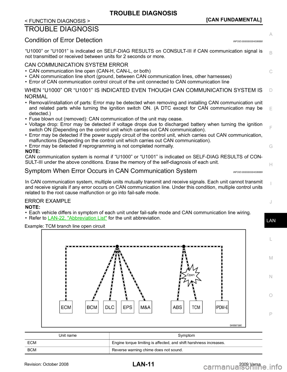
Symptom When Error Occurs in CAN Communication System INFOID:0000000004306689
In CAN communication system, multiple units mutually transmit and receive signals. Each unit cannot transmit
and receive signals if any error occurs on CAN communicati on line. Under this condition, multiple control units
related to the root cause malfunction or go into fail-safe mode.
ERROR EXAMPLE NOTE:
• Each vehicle differs in symptom of each unit under fail-safe mode and CAN communication line wiring.
• Refer to LAN-22, " Abbreviation List " for the unit abbreviation.
Example: TCM branch line open circuit
Page 3408 of 4331
LAN
N
O P
Example: Main Line Between Data Link
Connector and ABS Actuator and Electr ic Unit (Control Unit) Open Circuit
Example: CAN-H, CAN-L Harness Short Circuit
Page 3409 of 4331

DTC
Self-diagnosis item
(CONSULT-III indication) DTC detection condition Inspection/Action
U0101 LOST COMM (TCM) When ECM is not transmitting or receiving CAN
communication signal of OBD (emission-related
diagnosis) from TCM for 2 seconds or more.
Start the inspection. Re-
fer to the applicable sec-
tion of the indicated
control unit.
U0140 LOST COMM (BCM)
When ECM is not transmitting or receiving CAN
communication signal of OBD (emission-related
diagnosis) from BCM for 2 seconds or more.
U1000 CAN COMM CIRCUIT When a control unit (except for ECM) is not
transmitting or receiving CAN communication
signal for 2 seconds or more.
U1001 CAN COMM CIRCUIT When ECM is not transmitting or receiving CAN
communication signal for 2 seconds or more.
U1002 SYSTEM COMM When a control unit is not transmitting or receiv-
ing CAN communication signal for 2 seconds or
less.
U1010 CONTROL UNIT(CAN) When an error is detected during the initial diag-
nosis for CAN controller of each control unit. Replace the control unit
indicating “U1010” or
“P0607”.
P0607 ECM