Page 373 of 4331
AT-368< SERVICE INFORMATION >
ASSEMBLY
28. Install lip seals (1) for band servo oil holes on transaxle case.
29. Install control valve assembly on transaxle case.
a. Install O-ring on terminal body. CAUTION:
• Do not reuse O-ring.
• Apply ATF to O-ring.
b. Insert manual valve into control valve assembly. CAUTION:
Be careful not to drop manual valve.
c. Set manual shaft in “N” position.
d. Install control valve assembly on transaxle case while aligning manual valve (2) with manual plate (1).
e. Install terminal body (2) into transaxle case by pushing it.
f. Install snap ring (1) to terminal body (2).
g. Tighten bolts (A), (B) and (C) to the specified torque. Refer to AT-236, " Component " . SCIA5895J
SCIA3999E
SCIA7090E
SCIA6030J
Page 375 of 4331
AT-370< SERVICE INFORMATION >
ASSEMBLY
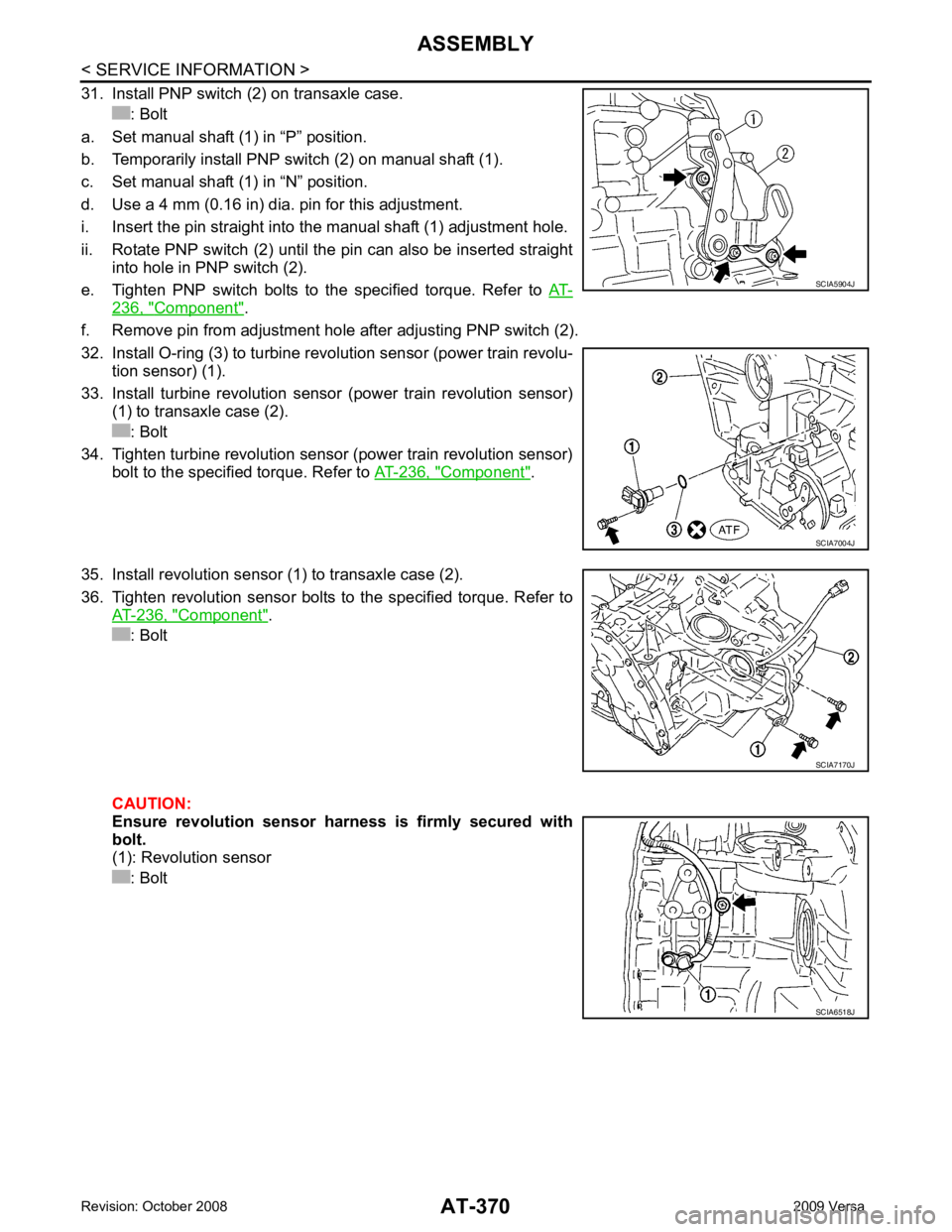
31. Install PNP switch (2) on transaxle case. : Bolt
a. Set manual shaft (1) in “P” position.
b. Temporarily install PNP switch (2) on manual shaft (1).
c. Set manual shaft (1) in “N” position.
d. Use a 4 mm (0.16 in) dia. pin for this adjustment.
i. Insert the pin straight into the manual shaft (1) adjustment hole.
ii. Rotate PNP switch (2) until the pin can also be inserted straight into hole in PNP switch (2).
e. Tighten PNP switch bolts to the specified torque. Refer to AT-236, " Component " .
f. Remove pin from adjustment hole after adjusting PNP switch (2).
32. Install O-ring (3) to turbine revolution sensor (power train revolu- tion sensor) (1).
33. Install turbine revolution sensor (power train revolution sensor) (1) to transaxle case (2).
: Bolt
34. Tighten turbine revolution sensor (power train revolution sensor) bolt to the specified torque. Refer to AT-236, " Component " .
35. Install revolution sensor (1) to transaxle case (2).
36. Tighten revolution sensor bolts to the specified torque. Refer to AT-236, " Component " .
: Bolt
CAUTION:
Ensure revolution sensor harness is firmly secured with
bolt.
(1): Revolution sensor
: Bolt SCIA5904J
SCIA7004J
SCIA7170J
SCIA6518J
Page 385 of 4331
AV
N
O P
CONTENTS
AUDIO, VISUAL, NAVIGATION & TELEPHONE SYS-
TEM
SERVICE INFORMATION .. ..........................2
PRECAUTIONS .............................................. .....2
Precaution for Supplemental Restraint System
(SRS) "AIR BAG" and "SEAT BELT PRE-TEN-
SIONER" ............................................................. ......
2
PREPARATION .............................................. .....3
Commercial Service Tool .................................... ......3
AUDIO ............................................................ .....4
Component Parts Location .................................. ......4
System Description ............................................. ......4
Schematic ........................................................... ......6
Wiring Diagram - AUDIO - ................................... ......8
Audio Unit (Base System) Harness Connector
Terminal Layout .................................................. ....
16
Terminal and Reference Value for Audio Unit
(Base System) ..................................................... ....
16
Audio Unit (Mid Level and Premium System) Har-
ness Connector Terminal Layout ........................ ....
17
Terminal and Reference Value for Audio Unit (Mid
Level and Premium System) ............................... ....
17
Subwoofer Harness Connector Terminal Layout
(Premium Audio System) .................................... ....
20
Terminal and Reference Value for Subwoofer
(Premium Audio System) .................................... ....
20
Satellite Radio Tuner Ha rness Connector Termi-
nal Layout ............................................................ ....
20
Terminal and Reference Value for Satellite Radio
Tuner ................................................................... ....
21
Trouble Diagnosis ............................................... ....21
Noise Inspection .................................................. ....22
Power Supply Circuit Inspection ......................... ....23
Satellite Radio Tuner (Fac tory Installed) Power
and Ground Supply Circuit Inspection ................. ....
24
Satellite Radio Tuner (Fac tory Installed) Commu-
nication Circuit Inspection ................................... ....
25
Satellite Radio Tuner (Fac tory Installed) Left
Channel Audio Signal Circuit Inspection ............. ....
27 Satellite Radio Tuner (Fac
tory Installed) Right
Channel Audio Signal Circuit Inspection ............. ....
27
Steering Switch Check (With Bluetooth) .............. ....28
Sound Is Not Heard from Front Door Speaker
(Base System) ..................................................... ....
30
Sound Is Not Heard from Rear Door Speaker
(Base System) ..................................................... ....
31
Sound Is Not Heard from Front Door Speaker or
Tweeter (Mid Level and Premium System) .............
32
Sound Is Not Heard from Rear Door Speaker (Mid
Level and Premium System) ............................... ....
33
Sound Is Not Heard from Subwoofer (Premium
System) ............................................................... ....
35
Removal and Installation ..................................... ....37
AUDIO ANTENNA ............................................. 42
Location of Antenna ............................................. ....42
Removal and Installation of Roof Antenna ..............42
TELEPHONE ..................................................... 44
Component Parts and Harness Connector Loca-
tion ....................................................................... ....
44
System Description .............................................. ....44
Wiring Diagram - H/PHON - ................................ ....46
Bluetooth Control Unit Harness Connector Termi-
nal Layout ............................................................ ....
48
Terminal and Reference Value for Bluetooth Con-
trol Unit ................................................................ ....
48
Bluetooth Control Unit Se lf-Diagnosis Function ......49
Workflow .............................................................. ....50
Power Supply and Ground Circuit Inspection for
Bluetooth Control Unit .. ...........................................
50
Basic Inspection of Hands-Free Phone ............... ....51
Steering Wheel Audio Co ntrol Switch Does Not
Operate ................................................................ ....
52
Voice Activated Control Fu nction Does Not Oper-
ate ........................................................................ ....
53
Removal and Installation ..................................... ....55
Page 387 of 4331
AV
N
O P
PREPARATION
Commercial Service Tool INFOID:0000000004306953
Tool name Description
Power tool Loosening bolts and nuts
Page 403 of 4331
AUDIO
AV-19
< SERVICE INFORMATION >
C
D E
F
G H
I
J
L
M A
B AV
N
O P
*1: With premium system
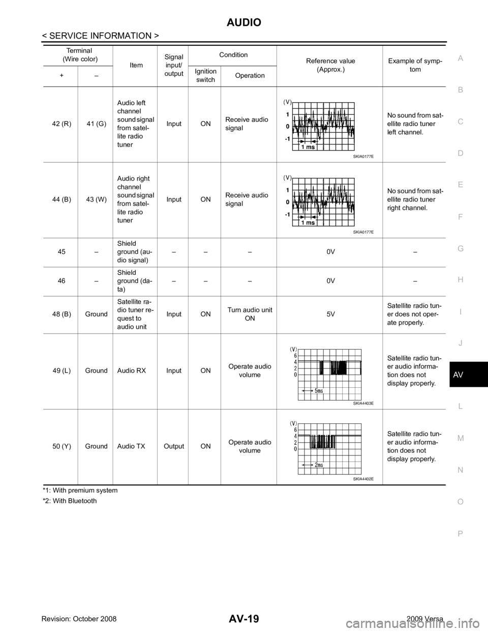
*2: With Bluetooth 42 (R) 41 (G)
Audio left
channel
sound signal
from satel-
lite radio
tuner Input ON
Receive audio
signal No sound from sat-
ellite radio tuner
left channel.
44 (B) 43 (W) Audio right
channel
sound signal
from satel-
lite radio
tuner Input ON
Receive audio
signal No sound from sat-
ellite radio tuner
right channel.
45 – Shield
ground (au-
dio signal) – – – 0V –
46 – Shield
ground (da-
ta) – – – 0V –
48 (B) Ground Satellite ra-
dio tuner re-
quest to
audio unit Input ON
Turn audio unit
ON 5VSatellite radio tun-
er does not oper-
ate properly.
49 (L) Ground Audio RX Input ON Operate audio
volume Satellite radio tun-
er audio informa-
tion does not
display properly.
50 (Y) Ground Audio TX Output ON Operate audio
volume Satellite radio tun-
er audio informa-
tion does not
display properly.
Terminal
(Wire color) ItemSignal
input/
output Condition
Reference value
(Approx.) Example of symp-
tom
+ – Ignition
switch Operation SKIA0177E
SKIA0177E
SKIA4403E
SKIA4402E
Page 405 of 4331
AUDIO
AV-21
< SERVICE INFORMATION >
C
D E
F
G H
I
J
L
M A
B AV
N
O P
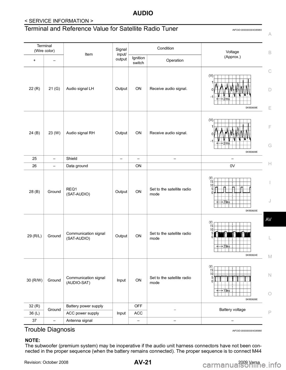
Terminal and Reference Valu
e for Satellite Radio Tuner INFOID:0000000004306965
Trouble Diagnosis INFOID:0000000004306966
NOTE:
The subwoofer (premium system) may be inoperative if the audio unit harness connectors have not been con-
nected in the proper sequence (when the battery remain s connected). The proper sequence is to connect M44
Terminal
(Wire color) ItemSignal
input/
output Condition
Voltage
(Approx.)
+ – Ignition
switch Operation
22 (R) 21 (G) Audio signal LH Output ON Receive audio signal.
24 (B) 23 (W) Audio signal RH Output ON Receive audio signal. 25 – Shield – – – –
26 – Data ground ON 0V
28 (B) Ground REQ1
(SAT-AUDIO) Output ONSet to the satellite radio
mode
29 (R/L) Ground Communication signal
(SAT-AUDIO) Output ONSet to the satellite radio
mode
30 (R/W) Ground Communication signal
(AUDIO-SAT) Input ON
Set to the satellite radio
mode
32 (R) GroundBattery power supply
InputOFF
− Battery voltage
36 (L) ACC power supply ACC
37 – Antenna signal – – – SKIB3609E
SKIB3609E
SKIB3825E
SKIB3824E
SKIB3826E
Page 417 of 4331
AUDIO
AV-33
< SERVICE INFORMATION >
C
D E
F
G H
I
J
L
M A
B AV
N
O P
OK or NG OK >> GO TO 2.
NG >> • Check connector housings for disconnected or loose terminals.
• Repair harness or connector. 2.
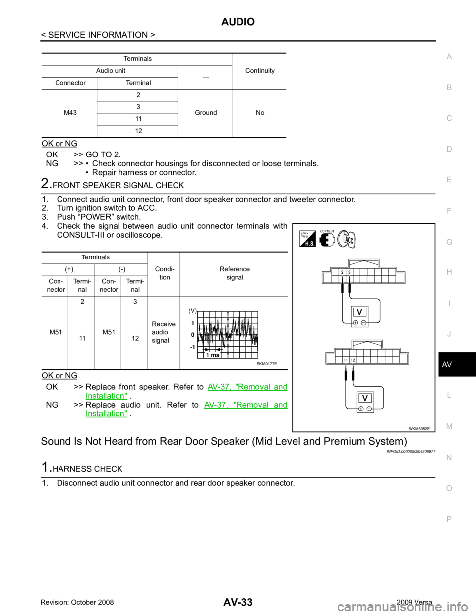
FRONT SPEAKER SIGNAL CHECK
1. Connect audio unit connector, front door speaker connector and tweeter connector.
2. Turn ignition switch to ACC.
3. Push “POWER” switch.
4. Check the signal between audio unit connector terminals with CONSULT-III or oscilloscope.
OK or NG OK >> Replace front speaker. Refer to
AV-37, " Removal and
Installation " .
NG >> Replace audio unit. Refer to AV-37, " Removal and
Installation " .
Sound Is Not Heard from Rear Door Sp eaker (Mid Level and Premium System)
INFOID:00000000043069771.
HARNESS CHECK
1. Disconnect audio unit connector and rear door speaker connector. Terminals
Continuity
Audio unit
—
Connector Terminal
M43 2
Ground No
3
11
12 Terminals
Condi-tion Reference
signal
(+) (-)
Con-
nector Termi-
nal Con-
nector Termi-
nal
M51 2
M51 3
Receive
audio
signal
11 12 WKIA5352ESKIA0177E
Page 418 of 4331
AV-34< SERVICE INFORMATION >
AUDIO
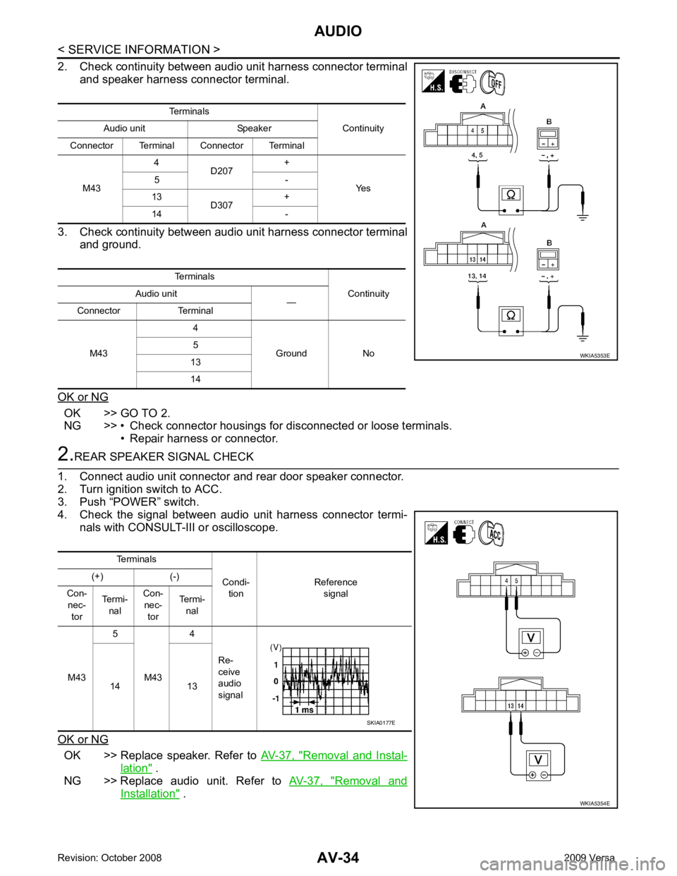
2. Check continuity between audio unit harness connector terminal and speaker harness connector terminal.
3. Check continuity between audio unit harness connector terminal and ground.
OK or NG OK >> GO TO 2.
NG >> • Check connector housings for disconnected or loose terminals.
• Repair harness or connector. 2.
REAR SPEAKER SIGNAL CHECK
1. Connect audio unit connector and rear door speaker connector.
2. Turn ignition switch to ACC.
3. Push “POWER” switch.
4. Check the signal between audio unit harness connector termi-
nals with CONSULT-III or oscilloscope.
OK or NG OK >> Replace speaker. Refer to
AV-37, " Removal and Instal-
lation " .
NG >> Replace audio unit. Refer to AV-37, " Removal and
Installation " .
Terminals
Continuity
Audio unit Speaker
Connector Terminal Connector Terminal
M43 4
D207 +
Yes
5 -
13 D307 +
14 -
Terminals Continuity
Audio unit
—
Connector Terminal
M43 4
Ground No
5
13
14 WKIA5353E
Terminals
Condi-tion Reference
signal
(+) (-)
Con- nec- tor Termi-
nal Con-
nec- tor Termi-
nal
M43 5
M43 4
Re-
ceive
audio
signal
14 13 WKIA5354ESKIA0177E