Page 281 of 4331
![NISSAN LATIO 2009 Service Repair Manual AT-276< SERVICE INFORMATION >
REPAIR FOR COMPONENT PARTS
1. Drive manual shaft oil seal into transaxle case using a drift [com- mercial service tool: 22 mm (0.87 in) dia.].
CAUTION:
• Do not reuse m NISSAN LATIO 2009 Service Repair Manual AT-276< SERVICE INFORMATION >
REPAIR FOR COMPONENT PARTS
1. Drive manual shaft oil seal into transaxle case using a drift [com- mercial service tool: 22 mm (0.87 in) dia.].
CAUTION:
• Do not reuse m](/manual-img/5/57359/w960_57359-280.png)
AT-276< SERVICE INFORMATION >
REPAIR FOR COMPONENT PARTS
1. Drive manual shaft oil seal into transaxle case using a drift [com- mercial service tool: 22 mm (0.87 in) dia.].
CAUTION:
• Do not reuse manual shaft oil seal.
• Apply ATF to outer surface of manual shaft oil seal.
2. Install parking rod to parking rod plate.
3. Insert manual shaft (1) to transaxle case, and install manual plate (2) to manual shaft (1).
4. Install parking rod plate (with parking rod) (3) to manual shaft (1).
5. Align groove of manual shaft and hole of transaxle case using a pin punch (A) [commercial service tool: 2 mm (0.08 in) dia.].
6. Drive retaining pin of manual shaft into transaxle case using Tool (B).
CAUTION:
Do not reuse retaining pin.
7. Set parking rod plate (1) onto manual shaft, and drive retaining pin (2) of parking rod plate (1) using tool (A).
CAUTION:
The retaining pin end should protrude approx. 3mm (0.12
in) (B) from the outer surface of parking rod plate (1).
8. Set manual plate (1) onto manual shaft, and drive retaining pin (2) of manual plate (1) using tool (A).
CAUTION:
The retaining pin end should protrude approx. 3mm (0.12
in) (B) from the outer surface of manual plate (1). SAT081D
SCIA7005E
Tool number: ST23540000 (J-25689-A)
SCIA7006E
Tool number: ST23540000 (J-25689-A)
SCIA7107E
Tool number: ST23540000 (J-25698-A)
SCIA7108E
Page 285 of 4331

AT-280< SERVICE INFORMATION >
REPAIR FOR COMPONENT PARTS
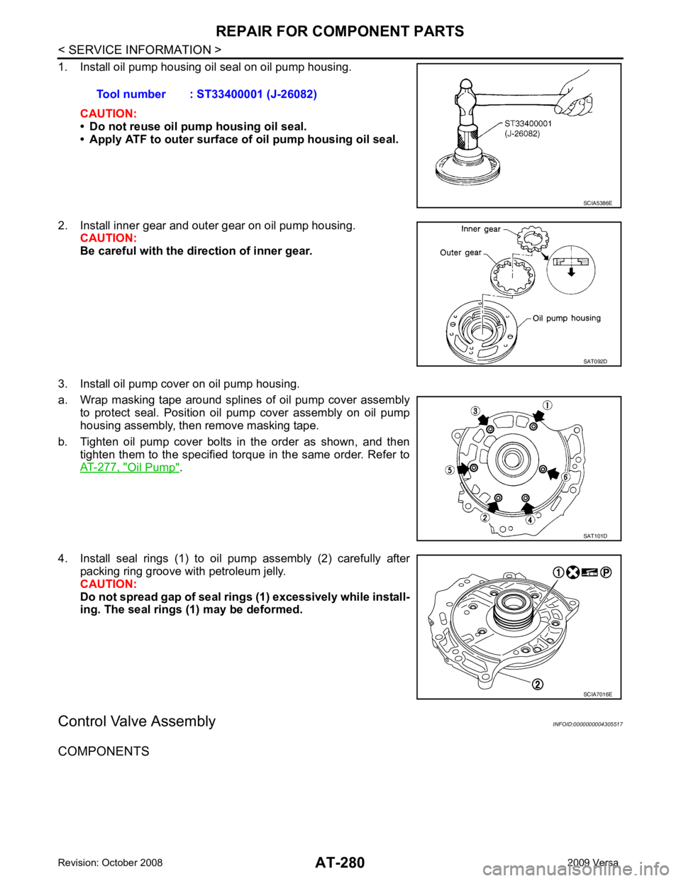
1. Install oil pump housing oil seal on oil pump housing.
CAUTION:
• Do not reuse oil pump housing oil seal.
• Apply ATF to outer surface of oil pump housing oil seal.
2. Install inner gear and outer gear on oil pump housing. CAUTION:
Be careful with the direction of inner gear.
3. Install oil pump cover on oil pump housing.
a. Wrap masking tape around splines of oil pump cover assembly to protect seal. Position oil pump cover assembly on oil pump
housing assembly, then remove masking tape.
b. Tighten oil pump cover bolts in the order as shown, and then tighten them to the specified torque in the same order. Refer to
AT-277, " Oil Pump " .
4. Install seal rings (1) to oil pump assembly (2) carefully after packing ring groove with petroleum jelly.
CAUTION:
Do not spread gap of seal ri ngs (1) excessively while install-
ing. The seal rings (1) may be deformed.
Control Valve Assembly INFOID:0000000004305517
COMPONENTS Tool number : ST33400001 (J-26082) SCIA5386E
SAT092D
SAT101D
SCIA7016E
Page 291 of 4331
AT-286< SERVICE INFORMATION >
REPAIR FOR COMPONENT PARTS
1. Install control valve upper, inter and lower body.
a. Place oil circuit of control valve upper body face up. Install steel balls in their proper positions.
b. Install reamer bolts (F) from bottom of control valve upper body (1). Using reamer bolts (F) as guides, install separating plate (2)
as a set.
c. Install pilot filter (1) on control valve upper body (2).
d. Place control valve inter body as shown (side of control valve lower body face up). Install steel balls in their proper positions.
e. Install control valve inter body (1) on control valve upper body (2) using reamer bolts (F) as guides.
CAUTION:
Be careful not to dislocate or drop steel balls. SAT871J
SCIA7010E
SCIA7011E
SAT870J
SCIA7012E
Page 300 of 4331

REPAIR FOR COMPONENT PARTS
AT-295
< SERVICE INFORMATION >
D
E
F
G H
I
J
K L
M A
B AT
N
O P
DISASSEMBLY
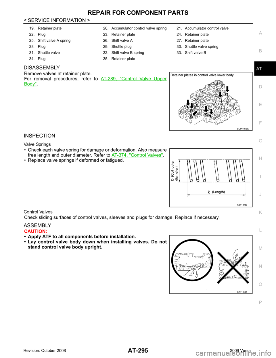
Remove valves at retainer plate.
For removal procedures, refer to AT-289, " Control Valve Upper
Body " .
INSPECTION
Valve Springs • Check each valve spring for damage or deformation. Also measure free length and outer diameter. Refer to AT-374, " Control Valves " .
• Replace valve springs if deformed or fatigued.
Control Valves Check sliding surfaces of control valves, sl eeves and plugs for damage. Replace if necessary.
ASSEMBLY CAUTION:
• Apply ATF to all componen ts before installation.
• Lay control valve body down wh en installing valves. Do not
stand control valve body upright. 19. Retainer plate 20. Accumulator control valve spring 21. Accumulator control valve
22. Plug 23. Retainer plate 24. Retainer plate
25. Shift valve A spring 26. Shift valve A 27. Retainer plate
28. Plug 29. Shuttle plug 30. Shuttle valve spring
31. Shuttle valve 32. Shift valve B spring 33. Shift valve B
34. Plug 35. Retainer plate SCIA4978E
SAT138D
SAT139D
Page 301 of 4331
AT-296< SERVICE INFORMATION >
REPAIR FOR COMPONENT PARTS
Install control valves.
For installation procedures, refer to AT-289, " Control Valve Upper
Body " .
Retainer Plate (Control Valve Lower Body)
Install proper retainer plates. Unit: mm (in)
Reverse Clutch INFOID:0000000004305520
COMPONENTS
DISASSEMBLY SCIA4978E
Lo-
cat- ion Retainer plate designation Width “A” Length “B” Type
L3 Pressure regulator valve 6.0
(0.236) 28.0
(1.102) I
L4 Overrun clutch control valve
L5 Accumulator control valve
L6 Shift valve A
L7 Shuttle valve
L12 Shift valve B 17.0
(0.669) 24.0
(0.945) II
L13 Pressure modifier valve 6.0
(0.236) 28.0
(1.102) I SAT089F
1. Reverse clutch drum 2. D-ring 3. Seal lip
4. Reverse clutch piston 5. Spring retainer assembly 6. Snap ring
7. Dish plate 8. Driven plate 9. Retaining plate
10. Snap ring 11. Drive plate SCIA6939J
Page 314 of 4331

REPAIR FOR COMPONENT PARTS
AT-309
< SERVICE INFORMATION >
D
E
F
G H
I
J
K L
M A
B AT
N
O P
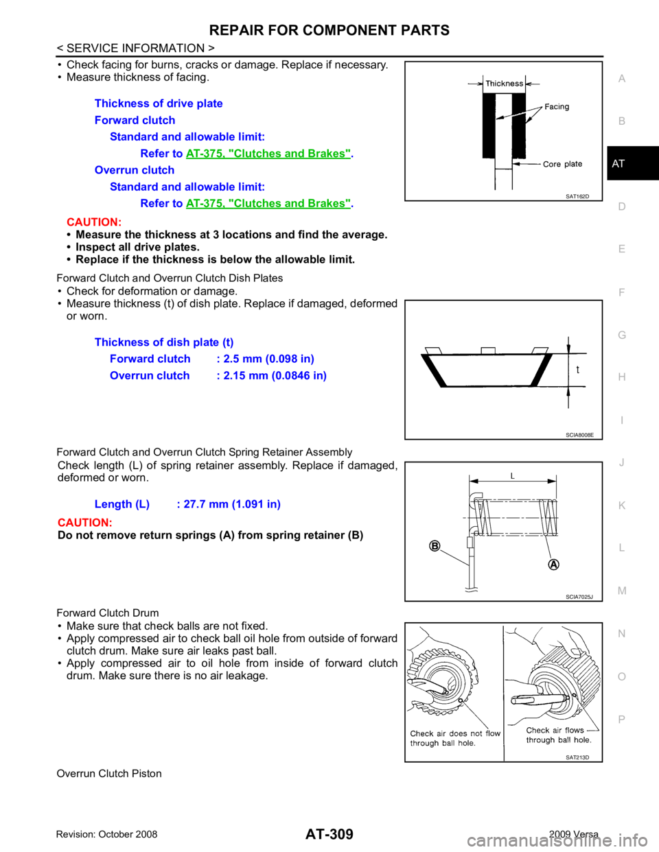
• Check facing for burns, cracks or
damage. Replace if necessary.
• Measure thickness of facing.
CAUTION:
• Measure the thickness at 3 lo cations and find the average.
• Inspect all drive plates.
• Replace if the thickness is below the allowable limit.
Forward Clutch and Overrun Clutch Dish Plates • Check for deformation or damage.
• Measure thickness (t) of dish plate. Replace if damaged, deformed or worn.
Forward Clutch and Overrun Clutch Spring Retainer Assembly Check length (L) of spring retainer assembly. Replace if damaged,
deformed or worn.
CAUTION:
Do not remove return springs (A) from spring retainer (B)
Forward Clutch Drum • Make sure that check balls are not fixed.
• Apply compressed air to check ball oil hole from outside of forward
clutch drum. Make sure air leaks past ball.
• Apply compressed air to oil hole from inside of forward clutch drum. Make sure there is no air leakage.
Overrun Clutch Piston Thickness of drive plate
Forward clutch Standard and allowable limit:
Refer to AT-375, " Clutches and Brakes " .
Overrun clutch Standard and allowable limit:
Refer to AT-375, " Clutches and Brakes " . SAT162D
Thickness of dish plate (t)
Forward clutch : 2.5 mm (0.098 in)
Overrun clutch : 2.15 mm (0.0846 in) SCIA8008E
Length (L) : 27.7 mm (1.091 in)
SCIA7025J
SAT213D
Page 320 of 4331
REPAIR FOR COMPONENT PARTS
AT-315
< SERVICE INFORMATION >
D
E
F
G H
I
J
K L
M A
B AT
N
O P
• Check facing for burns, cracks or
damage. Replace if necessary.
• Measure thickness of facing.
CAUTION:
• Measure the thickness at 3 lo cations and find the average.
• Inspect all drive plates.
• Replace if the thickness is below the allowable limit.
Low & Reverse Brake Dish Plates • Check for deformation or damage.
• Measure thickness (t) of dish plate. Replace if damaged, deformed
or worn.
Low & Reverse Brake Spring Retainer Assembly Check length (L) of spring retainer assembly. Replace if damaged,
deformed or worn.
CAUTION:
Do not remove return springs (A) from spring retainer (B)
ASSEMBLY 1. Install seal lip (1) and D-ring (2) on low & reverse brake piston (3).Thickness of drive plate
Standard and allowable limit:
Refer to AT-375, " Clutches and Brakes " .
SAT162D
Thickness of dish plate (t) : 2.93 mm (0.1154 in)
SCIA8008E
Length (L) : 26.3 mm (1.035 in)
SCIA7025J
SCIA6516J
Page 332 of 4331

REPAIR FOR COMPONENT PARTS
AT-327
< SERVICE INFORMATION >
D
E
F
G H
I
J
K L
M A
B AT
N
O P
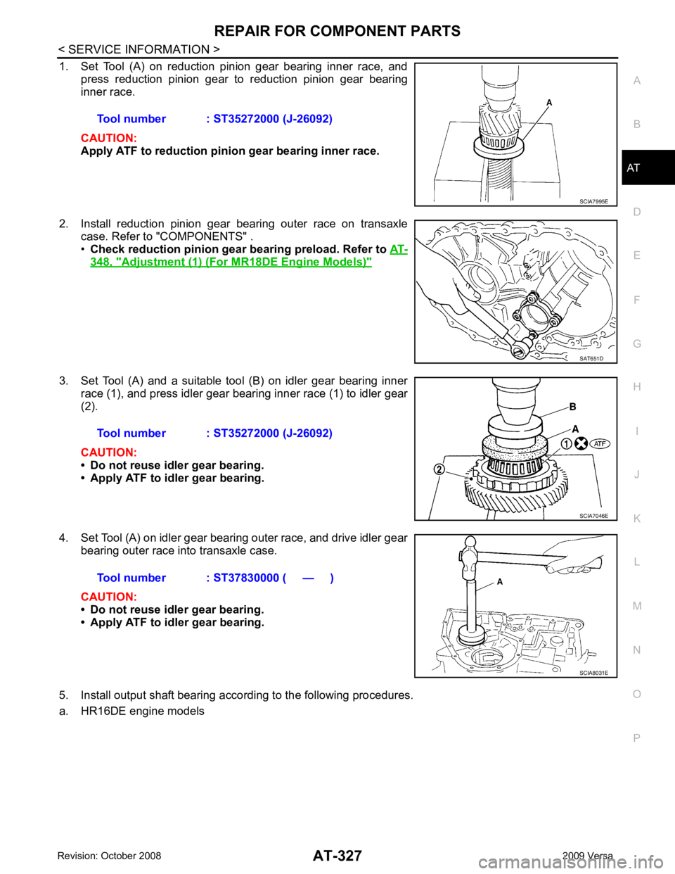
1. Set Tool (A) on reduction pinion gear bearing inner race, and
press reduction pinion gear to reduction pinion gear bearing
inner race.
CAUTION:
Apply ATF to reduction pinion gear bearing inner race.
2. Install reduction pinion gear bearing outer race on transaxle case. Refer to "COMPONENTS" .
• Check reduction pinion gear b earing preload. Refer to AT-348, " Adjustment (1) (For MR18DE Engine Models) "
3. Set Tool (A) and a suitable tool (B) on idler gear bearing inner
race (1), and press idler gear bearing inner race (1) to idler gear
(2).
CAUTION:
• Do not reuse idler gear bearing.
• Apply ATF to idler gear bearing.
4. Set Tool (A) on idler gear bearing outer race, and drive idler gear bearing outer race into transaxle case.
CAUTION:
• Do not reuse idler gear bearing.
• Apply ATF to idler gear bearing.
5. Install output shaft bearing according to the following procedures.
a. HR16DE engine models Tool number : ST35272000 (J-26092) SCIA7995E
SAT651D
Tool number : ST35272000 (J-26092)
SCIA7046E
Tool number : ST37830000 ( — )
SCIA8031E