2009 NISSAN LATIO service
[x] Cancel search: servicePage 24 of 4331
A/T FLUID
AT-19
< SERVICE INFORMATION >
D
E
F
G H
I
J
K L
M A
B AT
N
O P
13. Flush each steel line from the cooler side back to
ward the A/T by spraying Transmission Cooler Cleaner
in a continuous stream for 5 seconds.
14. Blow compressed air regulated to 5 - 9 kg/cm 2
(71 - 128 psi) through each steel line from the cooler side
back toward the A/T for 10 seconds to force out any remaining A/T fluid.
15. Ensure all debris is removed from the steel cooler lines.
16. Ensure all debris is removed from the banjo bolts and fittings.
17. Perform "A/T FLUID COOL ER DIAGNOSIS PROCEDURE".
A/T FLUID COOLER DIAGNOSIS PROCEDURE NOTE:
Insufficient cleaning of the cooler inlet hose exte rior may lead to inaccurate debris identification.
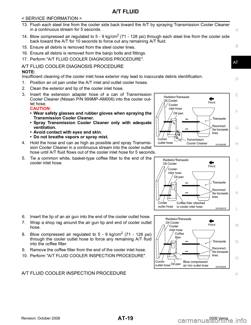
1. Position an oil pan under the A/T inlet and outlet cooler hoses.
2. Clean the exterior and tip of the cooler inlet hose.
3. Insert the extension adapter hose of a can of Transmission Cooler Cleaner (Nissan P/N 999MP-AM006) into the cooler out-
let hose.
CAUTION:
• Wear safety glasses and rubber gloves when spraying the
Transmission Cooler Cleaner.
• Spray Transmission Cooler Cleaner only with adequate
ventilation.
• Avoid contact with eyes and skin.
• Do not breathe vapors or spray mist.
4. Hold the hose and can as high as possible and spray Transmis- sion Cooler Cleaner in a continuous stream into the cooler outlet
hose until A/T fluid flows out of t he cooler inlet hose for 5 seconds.
5. Tie a common white, basket-type coffee filter to the end of the cooler inlet hose.
6. Insert the tip of an air gun into the end of the cooler outlet hose.
7. Wrap a shop rag around the air gun tip and end of cooler outlet hose.
8. Blow compressed air regulated to 5 - 9 kg/cm 2
(71 - 128 psi)
through the cooler outlet hose to force any remaining A/T fluid
into the coffee filter.
9. Remove the coffee filter from the end of the cooler inlet hose.
10. Perform "A/T FLUID COOL ER INSPECTION PROCEDURE".
A/T FLUID COOLER INSPECTION PROCEDURE SCIA5629E
SCIA5631E
SCIA5632E
Page 59 of 4331
AT-54< SERVICE INFORMATION >
TROUBLE DIAGNOSIS
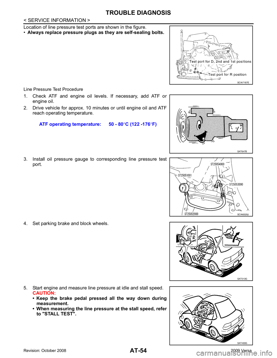
Location of line pressure test ports are shown in the figure.
• Always replace pressure plugs as they are self-sealing bolts.
Line Pressure Test Procedure
1. Check ATF and engine oil levels. If necessary, add ATF or engine oil.
2. Drive vehicle for approx. 10 minutes or until engine oil and ATF reach operating temperature.
3. Install oil pressure gauge to corresponding line pressure test port.
4. Set parking brake and block wheels.
5. Start engine and measure line pressure at idle and stall speed. CAUTION:
• Keep the brake pedal pressed all the way down during
measurement.
• When measuring the line pressure at the stall speed, refer to "STALL TEST". SCIA7187E
ATF operating temperature: 50 - 80
°C (122 -176 °F) SAT647B
SCIA6528J
SAT513G
SAT493G
Page 66 of 4331

TROUBLE DIAGNOSIS
AT-61
< SERVICE INFORMATION >
D
E
F
G H
I
J
K L
M A
B AT
N
O P
• Continue “Road Test”. 8.
CHECK SHIFT-DOWN (D 4 TO D 3 )
Decelerate vehicle by applying foot brake lightly. Read gear position and engine speed. Refer to AT-79, " CON-
SULT-III Functi
on (TRANSMISSION) " .
Does engine speed return to idle smoothly when A/T is shifted from D 4 to D 3 ?
YES >> 1. Stop vehicle.
2. Go to AT-61, " Cruise Test - Part 2 " .
NO >> • Mark the box on the “D iagnostic Worksheet Chart”.
• Go to AT-197, " Engine Speed Does Not Return to Idle
(Light Braking D 4 → D 3 ) " .
• Continue “Road Test”.
Cruise Test - Part 2 INFOID:00000000043053241.
CHECK STARTING GEAR (D 1 ) POSITION
1. Push overdrive control switch. (OD OFF indicator lamp is off.)
2. Move selector lever to “D” position.
3. Accelerate vehicle by half throttle again.
Read gear position. Refer to AT-79, " CONSULT-III Func-
tion (TRANSMISSION) " .
Does vehicle start from D 1 ?
YES >> GO TO 2.
NO >> • Mark the box on the “D iagnostic Worksheet Chart”.
• Go to AT-188, " Vehicle Cannot Be Started from D 1 " .
• Continue “Road Test”. 2.
CHECK SHIFT-UP AND SHIFT-DOWN (D 3 TO D 4 TO D 2 )
1. Accelerate vehicle to 80 km/h (50 MPH) as shown in the figure.
2. Release accelerator pedal and then quickly depress it fully.
Read gear position and th rottle opening. Refer to AT-79," CONSULT-III Function (TRANSMISSION) " .
Does A/T shift from D 4 to D 2 as soon as accelerator pedal is
depressed fully?
YES >> GO TO 3.
NO >> • Mark the box on the “D iagnostic Worksheet Chart”.
• Go to AT-190, " A/T Does Not Shift: D 1 → D 2 or Does
Not Kickdown: D 4 → D 2 " .
• Continue “Road Test”. 3.
CHECK SHIFT-UP (D 2 TO D 3 )
Check shift-up (D 2 to D 3 )
Specified speed when shifting from D 2 to D 3 . Refer to AT-64, " Vehicle Speed at Which Gear Shifting Occurs " .SAT959I
SAT495G
SCIA7192E
Page 84 of 4331

AT
N
O P
*1
: These terminals are connected to the data link connector.
*2 : These terminals are connected to the ECM.
CONSULT-III Function (TRANSMISSION) INFOID:0000000004305330
CONSULT-III can display each diagnostic item using the diagnostic test models shown following.
FUNCTION
CONSULT-III REFERENCE VALUE NOTICE:
1. The CONSULT-III electrically displays shift timi ng and lock-up timing (that is, operation timing of each
solenoid).
Check for time difference between actual shift timi ng and the CONSULT-III display. If the difference is
noticeable, mechanical parts (except solenoids, sens ors, etc.) may be malfunctioning. Check mechanical
parts using applicable diagnostic procedures.
2. Shift schedule (which implies gear position) display ed on CONSULT-III and that indicated in Service Man-
ual may differ slightly. This occurs because of the following reasons:
- Actual shift schedule has more or less tolerance or allowance,
- Shift schedule indicated in Service Manual re fers to the point where shifts start, and
- Gear position displayed on CONSULT-III indicates the point where shifts are completed.
3. Shift solenoid valve “A” or “B” is displayed on CONSUL T-III at the start of shifting. Gear position is dis-
played upon completion of shifting (which is computed by TCM).
39
*2
L Engine speed signal
and Refer to
EC-461 (HR16DE),
EC-597 (MR Type 1) or
EC- 1109 (MR Type 2).
40 O Vehicle speed sensor When driving vehicle at 2 to 3 km/h (1 to
2 MPH) for 1 m (3 ft) or more. Voltage varies
between less
than 0 V and
more than 4.5 V
42 B Sensor ground Always 0 V
47 BR A/T fluid temperature
sensor and When A/T fluid temperature is 20
°C
(68 °F). 1.5 V
When A/T fluid temperature is 80 °C
(176 °F). 0.5 V
48 B Ground Always 0 V
Terminal
Wire
color Item Condition Judgement stan-
dard (Approx.) Diagnostic test mode Function
Work Support This mode enables a technician to adjust some devices faster and more accuratelyI.
Self Diagnostic Results Retrieve DTC from ECU and display diagnostic items.
Data Monitor Monitor the input/output signal of the control unit in real time.
CAN Diagnosis Support Monitor It monitors the status of CAN communication.
Function Test This mode can show results of self-diagnosis of ECU with either “OK” or “NG”. For engine, more
practical tests regarding sensors/switches and/or actuators are available.
DTC & SRT confirmation The status of system monitoring tests and the self-diagnosis status/result can be confirmed.
ECU Identification Display the ECU identification number (part number etc.) of the selected system. Item name Condition Display value (Approx.)
VHCL/S SE-A/T During driving Approximately matches the speedometer
reading.
VHCL/S SE-MTR
THROTTLE POSI Released accelerator pedal. 0.0/8
Fully depressed accelerator pedal. 8.0/8
Page 89 of 4331

AT-84< SERVICE INFORMATION >
TROUBLE DIAGNOSIS
Description
If a malfunction occurs in electrical system, turning igni tion switch ON will illuminate OD OFF indicator lamp for
2 seconds. To detect a malfunction, entering a self-diagnosis start signal retrieves information on malfunctions
from memory and indicates malfunction by blinking OD OFF indicator lamp.
Diagnostic Procedure 1.
CHECK OD OFF INDICATOR LAMP
1. Park vehicle on flat surface.
2. Move selector lever to “P” position.
3. Turn ignition switch OFF. Wait at least 5 seconds.
4. Turn ignition switch ON. (Do not start engine.)
Does OD OFF indicator lamp come on about 2 seconds? YES >> GO TO 2.
NO >> Stop procedure. Perform AT-181, " OD OFF Indicator
Lamp Does Not Come On " before proceeding.
2.
JUDGEMENT PROCEDURE STEP 1
1. Turn ignition switch OFF.
2. Keep pressing shift lock release button.
3. Move selector lever from “P” to “D” position.
4. Turn ignition switch ON. (Do not start engine.)
5. Keep pressing overdrive control switch while OD OF F indicator lamp is lighting up for 2 seconds. (OD
OFF indicator lamp is on.)
6. Keep pressing overdrive control switch and shift select or lever to the “2” position. (OD OFF indicator lamp
is on.)
7. Stop pressing overdrive control switch. (OD OFF indicator lamp is on.)
8. Shift selector lever to the “1” position. (OD OFF indicator lamp is on.)
9. Keep pressing overdrive control switch. (OD OFF indicator lamp is off.)
10. Depress accelerator pedal fully while pressing overdrive control switch.
>> GO TO 3. 3.
CHECK SELF-DIAGNOSIS CODE
Check OD OFF indicator lamp. Refer to "Judgement of Self-diagnosis Code" .
>>DIAGNOSIS END
Judgement of Self-diagnosis Code SCIA5472E
SCIA7140E
Page 105 of 4331
AT-100< SERVICE INFORMATION >
DTC P0710 A/T FLUID TEMP
ERATURE SENSOR CIRCUIT
OK >> INSPECTION END
NG >> GO TO 8. 8.
CHECK TCM
1. Check TCM input/output signal. Refer to AT-77, " TCM Terminal and Reference Value " .
2. If NG, recheck TCM pin terminals for damage or loose connection with harness connector.
OK or NG OK >>
INSPECTION END
NG >> Repair or replace damaged parts.
Component Inspection INFOID:0000000004305353
A/T FLUID TEMPERATURE SENSOR
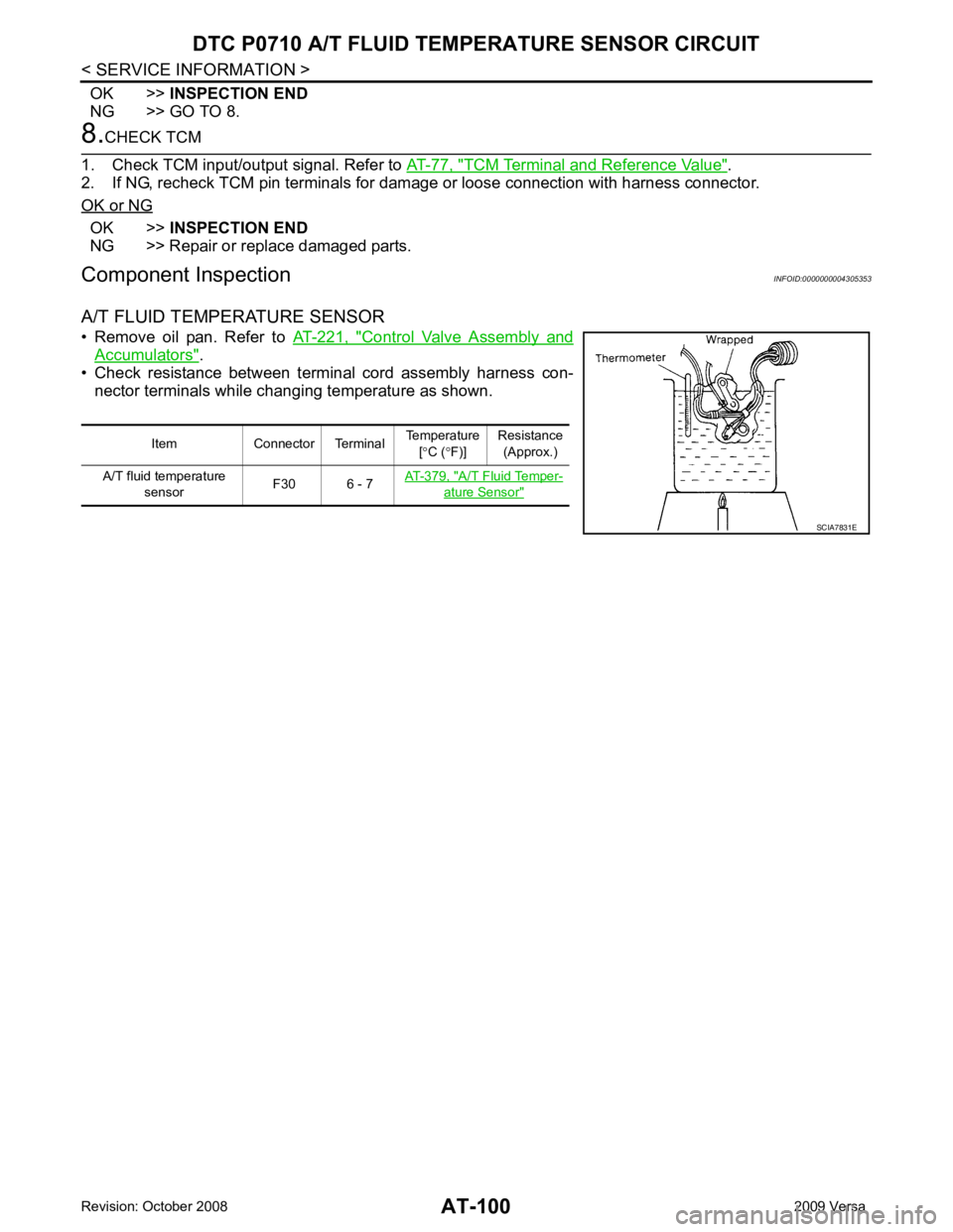
• Remove oil pan. Refer to AT-221, " Control Valve Assembly and
Accumulators " .
• Check resistance between terminal cord assembly harness con-
nector terminals while changing temperature as shown.
Item Connector Terminal Temperature
[° C ( °F)] Resistance
(Approx.)
A/T fluid temperature sensor F30 6 - 7
AT-379, " A/T Fluid Temper-
ature Sensor "
SCIA7831E
Page 122 of 4331
DTC P0733 A/T 3RD GEAR FUNCTION
AT-117
< SERVICE INFORMATION >
D
E
F
G H
I
J
K L
M A
B AT
N
O P
-
Make sure that “GEAR” shows “4” after releasing pedal.
6. Depress accelerator pedal steadily with 3.5/8 - 4.5/ 8 of “THROTTLE POSI” from a speed of 60 to 75 km/h
(37 to 47 MPH) until “TESTING” changes to “STOP VE HICLE” or “COMPLETED”. (It will take approxi-
mately 3 seconds.)
If the check result NG appears on CONSULT-III screen, go to AT-117, " Diagnosis Procedure " .
If “STOP VEHICLE” appears on CONSULT-III screen, go to following step.
- Make sure that “GEAR” shows “3” when depr essing accelerator pedal with 3.5/8 - 4.5/8 of
“THROTTLE POSI”.
- If “TESTING” does not appear on CONSULT-III fo r a long time, select “SELF-DIAG RESULTS” for
“TRANSMISSION”. In case a DTC ot her than “P0733 A/T 3RD GR FNCTN” is shown, refer to AT-79," CONSULT-III Function (TRANSMISSION) " .
7. Stop vehicle.
8. Follow the instruction displayed. (Check for normal shifting referring to the table below.)
9. Make sure that “OK” is disp layed. (If “NG” is displayed, refer to “Diagnostic Procedure”.)
Refer to AT-117, " Diagnosis Procedure " .
Refer to AT-64, " Vehicle Speed at Which Gear Shifting Occurs " .
WITH GST
Follow the procedure “WITH CONSULT-III”.
Diagnosis Procedure INFOID:00000000043053821.
CHECK VALVE RESISTANCE
1. Remove control valve assembly. Refer to AT-221, " Control Valve Assembly and Accumulators " .
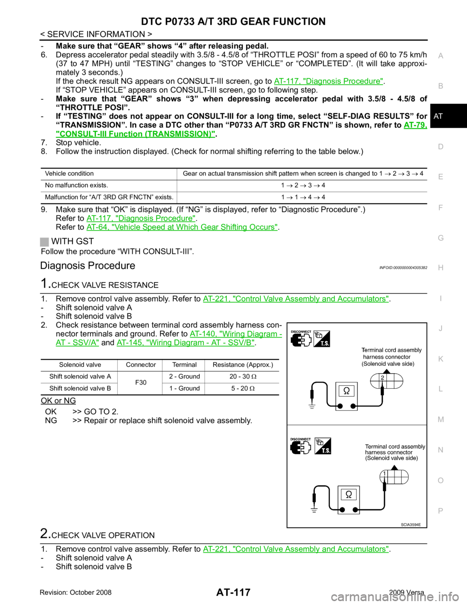
- Shift solenoid valve A
- Shift solenoid valve B
2. Check resistance between terminal cord assembly harness con- nector terminals and ground. Refer to AT-140, " Wiring Diagram -
AT - SSV/A " and
AT-145, " Wiring Diagram - AT - SSV/B " .
OK or NG OK >> GO TO 2.
NG >> Repair or replace shift solenoid valve assembly. 2.
CHECK VALVE OPERATION
1. Remove control valve assembly. Refer to AT-221, " Control Valve Assembly and Accumulators " .
- Shift solenoid valve A
- Shift solenoid valve B Vehicle condition Gear on actual transmission shift pattern when screen is changed to 1
→ 2 → 3 → 4
No malfunction exists. 1 → 2 → 3 → 4
Malfunction for “A/T 3 RD GR FNCTN” exists. 1 → 1 → 4 → 4 Solenoid valve Connector Terminal Resistance (Approx.)
Shift solenoid valve A F302 - Ground 20 - 30
Ω
Shift solenoid valve B 1 - Ground 5 - 20 Ω SCIA3594E
Page 123 of 4331
AT-118< SERVICE INFORMATION >
DTC P0733 A/T 3RD GEAR FUNCTION
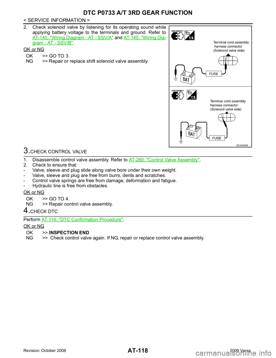
2. Check solenoid valve by listening for its operating sound while applying battery voltage to the terminals and ground. Refer to
AT-140, " Wiring Diagram - AT - SSV/A " and
AT-145, " Wiring Dia-
gram - AT - SSV/B " .
OK or NG OK >> GO TO 3.
NG >> Repair or replace shift solenoid valve assembly. 3.
CHECK CONTROL VALVE
1. Disassemble control valve assembly. Refer to AT-280, " Control Valve Assembly " .
2. Check to ensure that:
- Valve, sleeve and plug slide along valve bore under their own weight.
- Valve, sleeve and plug are free from burrs, dents and scratches.
- Control valve springs are free from damage, deformation and fatigue.
- Hydraulic line is free from obstacles.
OK or NG OK >> GO TO 4.
NG >> Repair control valve assembly. 4.
CHECK DTC
Perform AT-116, " DTC Confirmation Procedure " .
OK or NG OK >>
INSPECTION END
NG >> Check control valve again. If NG, repair or replace control valve assembly. SCIA3595E