2009 NISSAN LATIO window
[x] Cancel search: windowPage 2483 of 4331

EC
NP
O
P/N POSI SW • Ignition switch: ON
Shift lever: P or N (A/T, CVT),
Neutral (M/T) ON
Shift lever: Except above OFF
PW/ST SIGNAL • Engine: After warming up, idle the
engine Steering wheel: Not being turned OFF
Steering wheel: Being turned ON
LOAD SIGNAL • Ignition switch: ON Rear window defogger switch: ON
and/or Lighting switch: 2nd ON
Rear window defogger switch and light-
ing switch: OFF OFF
IGNITION SW • Ignition switch: ON → OFF → ON ON → OFF → ON
HEATER FAN SW • Ignition switch: ON Heater fan: Operating ON
Heater fan: Not operating OFF
BRAKE SW • Ignition switch: ON Brake pedal: Fully released OFF
Brake pedal: Slightly depressed ON
INJ PULSE-B1 • Engine: After warming up
• Air conditioner switch: OFF
• Shift lever: P or N (A/T, CVT), Neutral (M/T)
• No load Idle 2.0 - 3.0 msec
2,000 rpm 1.9 - 2.9 msec
IGN TIMING • Engine: After warming up
• Air conditioner switch: OFF
• Shift lever: P or N (A/T, CVT), Neutral (M/T)
• No load Idle 8
° - 18 ° BTDC
2,000 rpm 25 ° - 45 ° BTDC
CAL/LD VALUE • Engine: After warming up
• Air conditioner switch: OFF
• Shift lever: P or N (A/T, CVT),
Neutral (M/T)
• No load Idle 10% - 35%
2,500 rpm 10% - 35%
MASS AIRFLOW • Engine: After warming up
• Air conditioner switch: OFF
• Shift lever: P or N (A/T, CVT), Neutral (M/T)
• No load Idle 1.0 - 4.0 g·m/s
2,500 rpm 2.0 - 10.0 g·m/s
PURG VOL C/V • Engine: After warming up
• Air conditioner switch: OFF
• Shift lever: P or N (A/T, CVT), Neutral (M/T)
• No load Idle
(Accelerator pedal is not depressed
even slightly, after engine starting) 0%
2,000 rpm 0 - 50%
INT/V TIM (B1) • Engine: After warming up
• Air conditioner switch: OFF
• Shift lever: P or N (A/T, CVT), Neutral (M/T)
• No load Idle
−5 ° - 5 °CA
When revving engine up to 2,000 rpm
quickly Approx. 0
° - 40 °CA
INT/V SOL (B1) • Engine: After warming up
• Air conditioner switch: OFF
• Shift lever: P or N (A/T, CVT),
Neutral (M/T)
• No load Idle 0% - 2%
When revving engine up to 2,000 rpm
quickly Approx. 0% - 90%
AIR COND RLY • Engine: After warming up, idle the
engine Air conditioner switch: OFF OFF
Air conditioner switch: ON
(Compressor operates) ON
FUEL PUMP RLY • For 1 second after turning ignition switch ON
• Engine running or cranking ON
• Except above conditions OFF
MONITOR ITEM CONDITION SPECIFICATION
Page 2667 of 4331
![NISSAN LATIO 2009 Service Repair Manual DTC P0441 EVAP CONTROL SYSTEM
EC-1311
< SERVICE INFOMATION >
[MR TYPE 2] C
D E
F
G H
I
J
K L
M A EC
NP
O
1. Start engine and warm it up to normal operating temperature.
2. Turn ignition switch OFF and NISSAN LATIO 2009 Service Repair Manual DTC P0441 EVAP CONTROL SYSTEM
EC-1311
< SERVICE INFOMATION >
[MR TYPE 2] C
D E
F
G H
I
J
K L
M A EC
NP
O
1. Start engine and warm it up to normal operating temperature.
2. Turn ignition switch OFF and](/manual-img/5/57359/w960_57359-2666.png)
DTC P0441 EVAP CONTROL SYSTEM
EC-1311
< SERVICE INFOMATION >
[MR TYPE 2] C
D E
F
G H
I
J
K L
M A EC
NP
O
1. Start engine and warm it up to normal operating temperature.
2. Turn ignition switch OFF and wait at least 10 seconds.
3. Start engine and let it idle for at least 70 seconds.
4. Select “PURG FLOW P0441” of “EVAPORATIVE SYSTEM” in “DTC CONFIRMATION” mode with CON-
SULT-III.
5. Touch “START”.
If “COMPLETED” is displayed, go to step 7.
6. When the following conditions are met, “TESTING ” will be displayed on the CONSULT-III screen. Maintain
the conditions continuously until “TES TING” changes to “COMPLETED”. (It will take at least 35 seconds.)
If TESTING is not changed for a long time, retry from step 2.
7. Make sure that “OK” is displayed after touching “S ELF-DIAG RESULTS”. If “NG” is displayed, refer to EC-1311, " Diagnosis Procedure " .
Overall Function Check INFOID:0000000004500173
Use this procedure to check the overall monitoring func tion of the EVAP control system purge flow monitoring.
During this check, a 1st trip DTC might not be confirmed.
WITH GST
1. Lift up drive wheels.
2. Start engine and warm it up to normal operating temperature.
3. Turn ignition switch OFF and wait at least 10 seconds.
4. Start engine and wait at least 70 seconds.
5. Set voltmeter probes to ECM te rminals 42 (EVAP control system
pressure sensor signal) and ground.
6. Check EVAP control system pressure sensor value at idle speed and note it.
7. Establish and maintain the following conditions for at least 1 minute.
8. Verify that EVAP contro l system pressure sensor value stays 0. 1V less than the value at idle speed (mea-
sured at step 6) for at least 1 second.
9. If NG, go to EC-1311, " Diagnosis Procedure " .
Diagnosis Procedure INFOID:00000000045001741.
CHECK EVAP CANISTER
1. Turn ignition switch OFF.
2. Check EVAP canister for cracks.
OK or NG OK (With CONSULT-III)>>GO TO 2.
OK (Without CONSULT-III)>>GO TO 3.
NG >> Replace EVAP canister. 2.
CHECK PURGE FLOW
Shift lever Suitable position
VHCL SPEED SE 32 - 120 km/h (20 - 75 MPH)
ENG SPEED 500 - 3,800 rpm
B/FUEL SCHDL 1.0 - 10.0 msec
COOLAN TEMP/S More than 0 °C Air conditioner switch ON
Headlamp switch ON
Rear window defogger switch ON
Engine speed Approx. 3,000 rpm
Shift lever Any position other than P, N or R PBIB3313E
Page 2862 of 4331

OK >> GO TO 2.
NG >> GO TO 4. OK >> GO TO 3.
NG >> GO TO 5. OK >>
INSPECTION END .
NG >> GO TO 6. or
LT-25 .
>> INSPECTION END Condition LOAD SIGNAL
Lighting switch: ON at 2nd position ON
Lighting switch: OFF OFF Condition LOAD SIGNAL
Rear window defogger switch: ON ON
Rear window defogger switch: OFF OFF Condition LOAD SIGNAL
Heater fan control switch: ON ON
Heater fan control switch: OFF OFF
Page 2920 of 4331

EI
N
O P
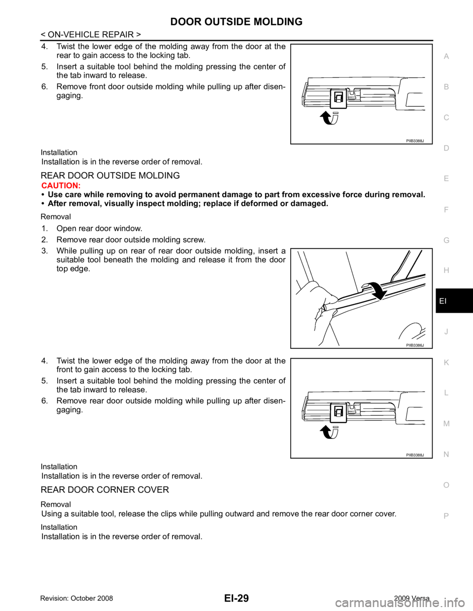
4. Twist the lower edge of the molding away from the door at the
rear to gain access to the locking tab.
5. Insert a suitable tool behind the molding pressing the center of the tab inward to release.
6. Remove front door outside molding while pulling up after disen- gaging.
Installation Installation is in the reverse order of removal.
REAR DOOR OUTSIDE MOLDING CAUTION:
• Use care while removing to avoid permanent da mage to part from excessive force during removal.
• After removal, visually inspect mold ing; replace if deformed or damaged.
Removal 1. Open rear door window.
2. Remove rear door outside molding screw.
3. While pulling up on rear of rear door outside molding, insert a suitable tool beneath the molding and release it from the door
top edge.
4. Twist the lower edge of the molding away from the door at the front to gain access to the locking tab.
5. Insert a suitable tool behind the molding pressing the center of the tab inward to release.
6. Remove rear door outside molding while pulling up after disen- gaging.
Installation Installation is in the reverse order of removal.
REAR DOOR CORNER COVER
Removal Using a suitable tool, release the clips while pulling outward and remove the rear door corner cover.
Installation Installation is in the reverse order of removal. PIIB3386J
Page 2926 of 4331

EI
N
O P
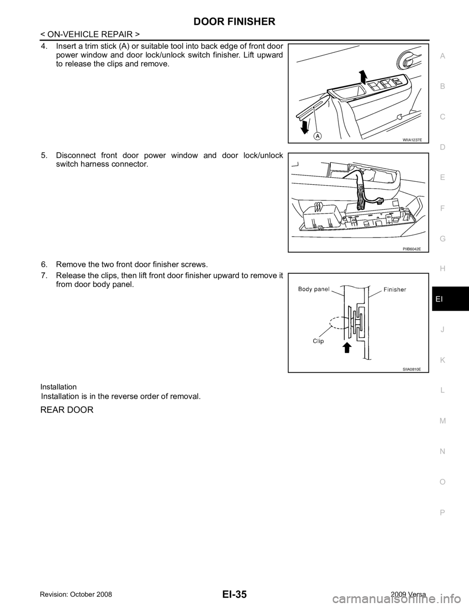
4. Insert a trim stick (A) or suitable tool into back edge of front door
power window and door lock/unlock switch finisher. Lift upward
to release the clips and remove.
5. Disconnect front door power window and door lock/unlock switch harness connector.
6. Remove the two front door finisher screws.
7. Release the clips, then lift front door finisher upward to remove it from door body panel.
Installation Installation is in the reverse order of removal.
REAR DOOR PIIB6042E
Page 3280 of 4331

GI
N
O P
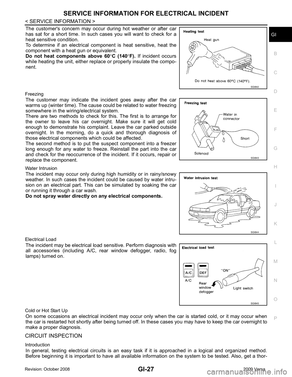
The customer's concern may occur during hot weather or after car
has sat for a short time. In such cases you will want to check for a
heat sensitive condition.
To determine if an electrical com ponent is heat sensitive, heat the
component with a heat gun or equivalent.
Do not heat components above 60 °C (140 °F). If incident occurs
while heating the unit, either replace or properly insulate the compo-
nent.
Freezing The customer may indicate the incident goes away after the car
warms up (winter time). The cause could be related to water freezing
somewhere in the wiring/electrical system.
There are two methods to check for this. The first is to arrange for
the owner to leave his car overnight. Make sure it will get cold
enough to demonstrate his complaint. Leave the car parked outside
overnight. In the morning, do a quick and thorough diagnosis of
those electrical components which could be affected.
The second method is to put the suspect component into a freezer
long enough for any water to freeze. Reinstall the part into the car
and check for the reoccurrence of the incident. If it occurs, repair or
replace the component.
Water Intrusion The incident may occur only during high humidity or in rainy/snowy
weather. In such cases the incident could be caused by water intru-
sion on an electrical part. This c an be simulated by soaking the car
or running it through a car wash.
Do not spray water directly on any electrical components.
Electrical Load The incident may be electrical load sensitive. Perform diagnosis with
all accessories (including A/C, rear window defogger, radio, fog
lamps) turned on.
Cold or Hot Start Up On some occasions an electrical incident may occur only when the car is started cold, or it may occur when
the car is restarted hot shortly after being turned off. In these cases you may have to keep the car overnight to
make a proper diagnosis.
CIRCUIT INSPECTION
Introduction In general, testing electrical circuits is an easy ta sk if it is approached in a logical and organized method.
Before beginning it is important to have all available in formation on the system to be tested. Also, get a thor- SGI843
SGI845
Page 3304 of 4331

GW
N
O P
CONTENTS
GLASSES, WINDOW SYSTEM & MIRRORS
SERVICE INFORMATION .. ..........................3
PRECAUTIONS .............................................. .....3
Precaution for Supplemental Restraint System
(SRS) "AIR BAG" and "SEAT BELT PRE-TEN-
SIONER" ............................................................. ......
3
Precaution Necessary fo r Steering Wheel Rota-
tion After Battery Disconnect ............................... ......
3
Precaution for Procedure without Cowl Top Cover ......4
Handling for Adhesive and Primer ...................... ......4
PREPARATION .............................................. .....5
Commercial Service Tool .................................... ......5
SQUEAK AND RATTLE TROUBLE DIAG-
NOSES ........................ ........................................6
Work Flow ........................................................... ......6
Generic Squeak and Rattle Troubleshooting ...... ......8
Diagnostic Worksheet ......................................... ....10
WINDSHIELD GLASS .................................... ....12
Removal and Installation .........................................12
OPERA WINDOW GLASS ............................. ....14
Removal and Installation .........................................14
REAR WINDOW GLASS AND MOLDING ..... ....16
Removal and Installation .........................................16
POWER WINDOW SYST EM ..............................19
Component Parts and Harness Connector Loca-
tion ...................................................................... ....
19
System Description ............................................. ....19
CAN Communication System Description ........... ....23
Schematic ........................................................... ....24
Wiring Diagram - WINDOW- ............................... ....25
Main Power Window and Door Lock/Unlock
Switch Harness Connector Terminal Layout ....... ....
29
Terminal and Reference Value for Main Power
Window and Door Lock/Unlock Switch ............... ....
29
Terminal and Reference Value for BCM ............. ....30
Work Flow ........................................................... ....30 CONSULT-III Function (B
CM) .................................30
Power Window Auto Operat ion Initialization ............31
Trouble Diagnosis Symptom Chart ...................... ....31
BCM Power Supply and Ground Circuit Inspection ....32
Main Power Window and Door Lock/Unlock
Switch Power Supply and Ground Circuit Inspec-
tion ....................................................................... ....
32
Front Power Window Motor LH Circuit Inspection ....33
Front Power Window RH Circuit Inspection (Pow-
er Window and Door Lock/Unlock Switch RH Op-
eration) ................................................................ ....
34
Front Power Window Motor RH Circuit Inspection ....34
Encoder Circuit Inspection ................................... ....36
Door Switch Check .............................................. ....38
Rear Power Window LH Circuit Inspection (Rear
Power Window Switch LH Operation) ................. ....
39
Rear Power Window RH Circu it Inspection (Rear
Power Window Switch RH Operation) ................. ....
40
Rear Power Window Motor LH Circuit Inspection ....40
Rear Power Window Motor RH Circuit Inspection ....42
FRONT DOOR GLASS AND REGULATOR ..... 44
Removal and Installation ..................................... ....44
Disassembly and Assembly ................................. ....46
Inspection after Installati on ......................................46
REAR DOOR GLASS AND REGULATOR ....... 48
Removal and Installation ..................................... ....48
Disassembly and Assembly ................................. ....50
Inspection after Installati on ......................................50
REAR WINDOW DEFOGGER .......................... 51
Component Parts and Harness Connector Loca-
tion ....................................................................... ....
51
System Description .............................................. ....51
CAN Communication System Description ........... ....52
Wiring Diagram - DEF - ....................................... ....53
Terminal and Reference Value for BCM ..................55
Terminal and Reference Va lue for IPDM E/R ..........55
Work Flow ............................................................ ....55
Page 3316 of 4331

GW
N
O P
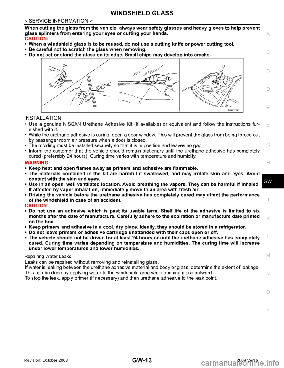
When cutting the glass from the vehicle, always
wear safety glasses and heavy gloves to help prevent
glass splinters from entering your eyes or cutting your hands.
CAUTION:
• When a windshield glass is to be reused, do no t use a cutting knife or power cutting tool.
• Be careful not to scratch the glass when removing.
• Do not set or stand the glass on its ed ge. Small chips may develop into cracks.
INSTALLATION • Use a genuine NISSAN Urethane Adhesive Kit (if availabl e) or equivalent and follow the instructions fur-
nished with it.
• While the urethane adhesive is curing, open a door window . This will prevent the glass from being forced out
by passenger room air pressure when a door is closed.
• The molding must be installed securely so that it is in position and leaves no gap.
• Inform the customer that the vehicle should rema in stationary until the urethane adhesive has completely
cured (preferably 24 hours). Curing time varies with temperature and humidity.
WARNING:
• Keep heat and open flames away as primers and adhesive are flammable.
• The materials contained in the kit are harmful if swallowed, and may irritate skin and eyes. Avoid
contact with the skin and eyes.
• Use in an open, well ventilated lo cation. Avoid breathing the vapors. They can be harmful if inhaled.
If affected by vapor inhalation, imme diately move to an area with fresh air.
• Driving the vehicle before the urethane adhesive has completely cured may affect the performance
of the windshield in case of an accident.
CAUTION:
• Do not use an adhesive which is past its usable te rm. Shelf life of the adhesive is limited to six
months after the date of manufacture. Carefully ad here to the expiration or manufacture date printed
on the box.
• Keep primers and adhesive in a cool, dry place. Id eally, they should be stored in a refrigerator.
• Do not leave primers or adhesive cartridge unattended with their caps open or off.
• The vehicle should not be driven for at least 24 hours or until the urethane adhesive has completely
cured. Curing time varies depend ing on temperature and humidities. The curing time will increase
under lower temperatures and lower humidities.
Repairing Water Leaks Leaks can be repaired without removing and reinstalling glass.
If water is leaking between the urethane adhesive material and body or glass, determine the extent of leakage.
This can be done by applying water to the windshield area while pushing glass outward.
To stop the leak, apply primer (if necessary ) and then urethane adhesive to the leak point.