Page 3109 of 4331
Component " .
NOTE:
When crankshaft sprocket, oil pump sprocket and other related parts are not removed, this step is unnec-
essary.
10. Remove intake valve timing control solenoid valve.
11. Remove drive belt auto-tensioner.
12. Loosen bolts in reverse order as shown.
13. Cut liquid gasket by prying the position ( ) shown, and then remove the front cover.
CAUTION:
• Be careful not to damage the mating surface.
• A more adhesive liquid gasket is applied compared to pre- vious types when shipped, so it should not be forced off
the position not specified.
14. Remove front oil seal from front cover. • Lift up front oil seal using a suitable tool.
CAUTION:
Be careful not to damage front cover. Tool number : KV11103000 ( — )
PBIC3164J
PBIC3357J
Page 3118 of 4331

EM
NP
O
• Rocker cover; Refer to
EM-153 .
• Fuel tube and fuel injector assembly; Refer to EM-156 .
• Front cover, timing chain and related parts; Refer to EM-160 .
7. Remove camshaft position sensor (PHASE) from camshaft bracket. CAUTION:
• Handle carefully to avoid dropping and shocks.
• Never disassemble.
• Never allow metal powder to adhere to magnetic part at sensor tip.
• Never place sensor in a location wher e it is exposed to magnetism.
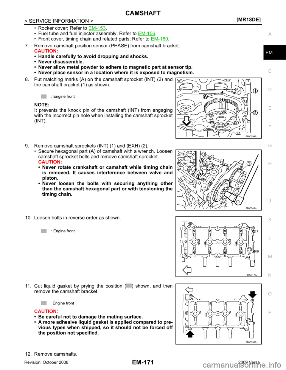
8. Put matching marks (A) on the camshaft sprocket (INT) (2) and the camshaft bracket (1) as shown.
NOTE:
It prevents the knock pin of the camshaft (INT) from engaging
with the incorrect pin hole when installing the camshaft sprocket
(INT).
9. Remove camshaft sprockets (INT) (1) and (EXH) (2). • Secure hexagonal part (A) of camshaft with a wrench. Loosen
camshaft sprocket bolts and remove camshaft sprocket.
CAUTION:
• Never rotate crankshaft or camshaft while timing chain
is removed. It causes interference between valve and
piston.
• Never loosen the bolts with securing anything other
than the camshaft hexagonal part or with tensioning the
timing chain.
10. Loosen bolts in reverse order as shown.
11. Cut liquid gasket by prying the position ( ) shown, and then remove the camshaft bracket.
CAUTION:
• Be careful not to damage the mating surface.
• A more adhesive liquid gasket is applied compared to pre-
vious types when shipped, so it should not be forced off
the position not specified.
12. Remove camshafts. : Engine front
PBIC3454J
Page 3124 of 4331
![NISSAN LATIO 2009 Service Repair Manual CAMSHAFT
EM-177
< SERVICE INFORMATION >
[MR18DE] C
D E
F
G H
I
J
K L
M A EM
NP
O
10. Install camshaft sprocket (EXH) (2).
NOTE:
Secure the hexagonal part (A) of camshaft (EXH) using wrench
to tighten NISSAN LATIO 2009 Service Repair Manual CAMSHAFT
EM-177
< SERVICE INFORMATION >
[MR18DE] C
D E
F
G H
I
J
K L
M A EM
NP
O
10. Install camshaft sprocket (EXH) (2).
NOTE:
Secure the hexagonal part (A) of camshaft (EXH) using wrench
to tighten](/manual-img/5/57359/w960_57359-3123.png)
CAMSHAFT
EM-177
< SERVICE INFORMATION >
[MR18DE] C
D E
F
G H
I
J
K L
M A EM
NP
O
10. Install camshaft sprocket (EXH) (2).
NOTE:
Secure the hexagonal part (A) of camshaft (EXH) using wrench
to tighten bolt.
11. Install timing chain and related parts. Refer to EM-160 .
12. Inspect and adjust valve clearance. Refer to EM-178, " Valve Clearance " .
13. Installation of the remaining components is in the reverse order of removal.
INSPECTION AFTER INSTALLATION The following are procedures for chec king fluids leak, lubricates leak.
• Before starting engine, check oil/fluid levels incl uding engine coolant and engine oil. If less than required
quantity, fill to the specified level. Refer to GI-42, " Recommended Chemical Product and Sealant " .
• Use procedure below to check for fuel leakage.
- Turn ignition switch “ON” (with engine stopped). With fuel pressure applied to fuel piping, check for fuel leak-
age at connection points.
- Start engine. With engine speed increased, check again for fuel leakage at connection points.
• Run engine to check for unusual noise and vibration. NOTE:
If hydraulic pressure inside timing chain tensioner drops after removal/installation, slack in the guide may
generate a pounding noise during and just after engine start. However, this is normal. Noise will stop after
hydraulic pressure rises.
• Warm up engine thoroughly to make sure there is no leak age of fuel, or any oil/fluids including engine oil and
engine coolant.
• Bleed air from lines and hoses of applicable lines, such as in cooling system.
• After cooling down engine, again check oil/fluid levels including engine oil and engine coolant. Refill to the
specified level, if necessary.
Summary of the inspection items:
* Transmission/transaxle/CVT fluid, power steering fluid, brake fluid, etc.
Inspection of Camshaft Sprocket (INT) Oil Groove
CAUTION:
• Perform this inspection only when DTC P0011 is detected in self-diagnostic results of CONSULT-III
and it is directed according to inspect ion procedure of EC section. Refer to EC-638, " Diagnosis Pro-
cedure " (Type 1) or
EC-1153, " Diagnosis Procedure " (Type 2).
• Check when engine is cold so as to pr event burns from the splashing engine oil.
1. Check engine oil level. Refer to LU-16, " Inspection " .
2. Perform the following procedure so as to prevent the engine from being unintentionally started while checking.
a. Remove intake manifold. Refer to EM-141, " Component " .
b. Disconnect ignition coil and in jector harness connectors.
3. Remove intake valve timing control solenoid valve. Refer to EM-160, " Component " .
1 : Camshaft sprocket (INT)
Camshaft sprocket
bolt (EXH) : 88.2 N·m (9.0 kg-m, 65 ft-lb) PBIC3454J
Item Before starting engine Engine running After engine stopped
Engine coolant Level Leakage Level
Engine oil Level Leakage Level
Other oils and fluid* Level Leakage Level
Fuel Leakage Leakage Leakage
Exhaust gases — Leakage —
Page 3133 of 4331
Trouble Diagnosis Introduction "
(Type 1) or
EC-1089, " Trouble Diagnosis Introduction " (Type 2).
Component INFOID:0000000004307151
Removal and Installation INFOID:0000000004307152
REMOVAL
WARNING:
• Put a “CAUTION: FLAMMABLE” sign in the workshop.
• Be sure to work in a well ventilate d area and furnish workshop with a CO
2 fire extinguisher.
• Do not smoke while servicing fuel system. Keep open flames and sparks away from the work area.
1. Release the fuel pressure. Refer to EC-574, " Fuel Pressure Check " (Type 1) or
EC-1086, " Fuel Pressure
Check " (Type 2).
2. Drain engine coolant and engine oil. Refer to CO-35 and
LU-16 .
CAUTION:
• Perform this step when the engine is cold.
• Never spill engine coolant an d engine oil on drive belt.
3. Remove front fender protector (RH). Refer to EI-24 .
1. Cylinder head assembly 2. Cylinder head bolt 3. Cylinder head gasket
A. Refer to EM-186
Page 3788 of 4331

MA
N
O P
Do not overfill.
4. Drive vehicle for approximately 5 minutes.
5. Re-check A/T fluid level at A/T fluid temperatures of 50° to 80 °C (122 ° to 176 °F) using “HOT” range on A/
T fluid level gauge.
CAUTION:
• When wiping the A/T fluid level gauge, always use lint-free cloth.
• Firmly fix the A/T fluid level ga uge to the A/T fluid charging pipe using the stopper attached.
6. Check A/T fluid condition and make any necessary repairs. Refer to AT-51, " Inspections Before Trouble
Diagnosis " . If the A/T fluid contains frictional material (clu
tches, bands, etc.), or if the A/T is repaired, over-
hauled, or replaced, inspect and clean the A/T fluid cooler mounted in the radiator. Refer to AT-18, " A/T
Fluid Cooler Cleaning " .
7. Install the removed A/T fluid level gauge into the A/T fluid charging pipe. CAUTION:
Firmly fix the A/T fluid level gaug e to the A/T fluid charging pipe using the stopper attached.
A/T FLUID : Changing A/T Fluid INFOID:0000000004803431
1. Warm up A/T fluid.
2. Stop engine.
3. Drain A/T fluid by removing the drain plug. Re install the drain plug to the specified torque.
CAUTION:
Do not reuse drain plug gasket.
4. Refill the transaxle with new specified A/T fluid th rough the A/T fluid charging pipe. Always refill the tran-
saxle with the same volume of A/T fluid that was drained out.
5. Run engine at idle speed for 5 minutes.
6. Check A/T fluid level and condition. Refer to MA-44, " A/T FLUID : Checking A/T Fluid " .
WHEELS
WHEELS : Balancing Wheels INFOID:0000000004683837
Adjust wheel balance using road wheel center.
CAUTION:
• Be careful not to scratch th e road wheel during removal.
• Use clip-on type wheel balance weights only.
Wheel balance (Maximum allowable unbalance): Drain plug: Refer to
AT-236, " Component " .
Fluid grade and capacity: Refer to MA-14 .
Maximum allowable unbalance Dynamic (At rim flange) Less than 5 g (0.18 oz) (one side)
Static (At rim flange) Less than 10 g (0.35 oz)