Page 3788 of 4331

MA
N
O P
Do not overfill.
4. Drive vehicle for approximately 5 minutes.
5. Re-check A/T fluid level at A/T fluid temperatures of 50° to 80 °C (122 ° to 176 °F) using “HOT” range on A/
T fluid level gauge.
CAUTION:
• When wiping the A/T fluid level gauge, always use lint-free cloth.
• Firmly fix the A/T fluid level ga uge to the A/T fluid charging pipe using the stopper attached.
6. Check A/T fluid condition and make any necessary repairs. Refer to AT-51, " Inspections Before Trouble
Diagnosis " . If the A/T fluid contains frictional material (clu
tches, bands, etc.), or if the A/T is repaired, over-
hauled, or replaced, inspect and clean the A/T fluid cooler mounted in the radiator. Refer to AT-18, " A/T
Fluid Cooler Cleaning " .
7. Install the removed A/T fluid level gauge into the A/T fluid charging pipe. CAUTION:
Firmly fix the A/T fluid level gaug e to the A/T fluid charging pipe using the stopper attached.
A/T FLUID : Changing A/T Fluid INFOID:0000000004803431
1. Warm up A/T fluid.
2. Stop engine.
3. Drain A/T fluid by removing the drain plug. Re install the drain plug to the specified torque.
CAUTION:
Do not reuse drain plug gasket.
4. Refill the transaxle with new specified A/T fluid th rough the A/T fluid charging pipe. Always refill the tran-
saxle with the same volume of A/T fluid that was drained out.
5. Run engine at idle speed for 5 minutes.
6. Check A/T fluid level and condition. Refer to MA-44, " A/T FLUID : Checking A/T Fluid " .
WHEELS
WHEELS : Balancing Wheels INFOID:0000000004683837
Adjust wheel balance using road wheel center.
CAUTION:
• Be careful not to scratch th e road wheel during removal.
• Use clip-on type wheel balance weights only.
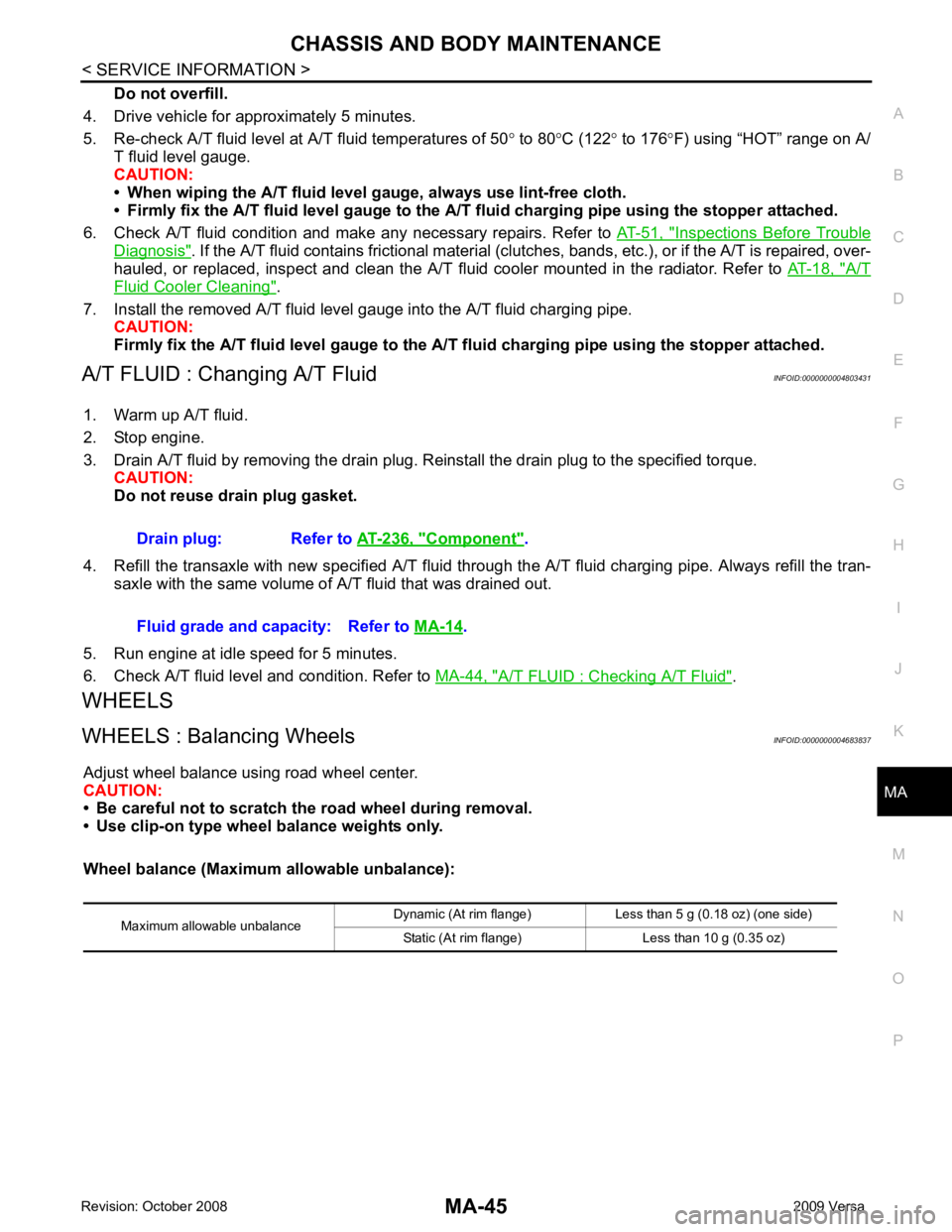
Wheel balance (Maximum allowable unbalance): Drain plug: Refer to
AT-236, " Component " .
Fluid grade and capacity: Refer to MA-14 .
Maximum allowable unbalance Dynamic (At rim flange) Less than 5 g (0.18 oz) (one side)
Static (At rim flange) Less than 10 g (0.35 oz)
Page 3937 of 4331
YES >> GO TO 3.
NO >> GO TO 2. Operational Check " .
Does another symptom exist? YES >> Refer to
MTC-22, " How to Perform Trouble Diagnosis for Quick and Accurate Repair " .
NO >> System OK. Inspection " (HR16DE) or
CO-35, " Inspection " (MR18DE).
2. Check hoses for leaks or kinks.
3. Check Radiator cap. Refer to CO-14, " Checking Radiator Cap " HR16DE or
CO-40, " Checking Radiator
Cap " (MR18DE).
OK or NG OK >> GO TO 5.
NG >> Repair/replace as necessary. Air Mix Door Cable Adjustment " .
OK or NG
Page 3969 of 4331

Removal and Installation " .
3. Remove high-pressure flexible hose and high-pressure pipe from condenser. Refer to MTC-82, " Removal
and Installation of High-Pressure Flexible Hose " and
MTC-83, " Removal and Installation of High-Pressure
Pipe " .
CAUTION:
Cap or wrap the joint of the pipe with suitable ma terial such as vinyl tape to avoid the entry of air.
4. Disconnect refrigerant pressure sensor connector.
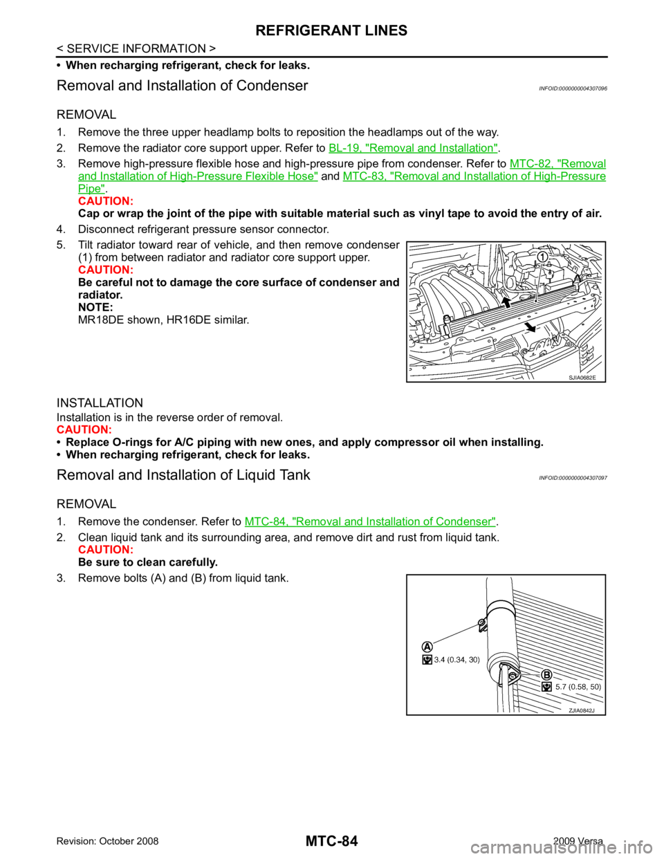
5. Tilt radiator toward rear of vehicle, and then remove condenser (1) from between radiator and radiator core support upper.
CAUTION:
Be careful not to damage the core surface of condenser and
radiator.
NOTE:
MR18DE shown, HR16DE similar.
INSTALLATION
Installation is in the reverse order of removal.
CAUTION:
• Replace O-rings for A/C piping with new ones, and apply compressor oil when installing.
• When recharging refrigerant, check for leaks.
Removal and Installation of Liquid Tank INFOID:0000000004307097
REMOVAL
1. Remove the condenser. Refer to MTC-84, " Removal and Installation of Condenser " .
2. Clean liquid tank and its surrounding area, and remove dirt and rust from liquid tank. CAUTION:
Be sure to clean carefully.
3. Remove bolts (A) and (B) from liquid tank. ZJIA0842J