2009 NISSAN LATIO radiator cap
[x] Cancel search: radiator capPage 934 of 4331
![NISSAN LATIO 2009 Service Repair Manual CO-40< SERVICE INFORMATION >
[MR18DE]
RADIATOR
Checking Radiator Cap INFOID:0000000004305238
• Check valve seat of radiator cap.
- Check if valve seat is swollen to the extent that the e NISSAN LATIO 2009 Service Repair Manual CO-40< SERVICE INFORMATION >
[MR18DE]
RADIATOR
Checking Radiator Cap INFOID:0000000004305238
• Check valve seat of radiator cap.
- Check if valve seat is swollen to the extent that the e](/manual-img/5/57359/w960_57359-933.png)
CO-40< SERVICE INFORMATION >
[MR18DE]
RADIATOR
Checking Radiator Cap INFOID:0000000004305238
• Check valve seat of radiator cap.
- Check if valve seat is swollen to the extent that the edge of the plunger cannot be seen when watching it vertically from the top.
- Check if valve seat has no soil and damage.
• Pull negative-pressure valve to open it, and make sure that it is completely closed when released.
- Make sure that there is no dirt or damage on the valve seat of radi-
ator cap negative-pressure valve.
- Make sure that the valve operates properly in the opening and closing conditions.
• Check radiator cap relief pressure using Tool.
- When connecting the radiator cap to the tester, apply water or coolant to the cap seal surface.
- Replace the radiator cap if ther e is an abnormality in the negative-
pressure valve, or if the open-valve pr essure is outside of the standard values.
• Replace radiator cap if there it does not comply to specifications to the above three checks.
CAUTION:
When installing radiator cap, thoroughly wipe out the radiator filler neck to remove any waxy residue
or foreign material.
Checking Radiator INFOID:0000000004305239
Check radiator for mud or clogging. If necessary, clean radiator as follows.
• Be careful not to bend or damage radiator fins.
• When radiator is cleaned without removal, remove all surrounding parts such as cooling fan, radiator shroud and horns. Then tape harness and connectors to prevent water from entering.
1. Apply water by hose to the back side of the radiator core vertically downward.
2. Apply water again to all radiator core surface once per minute.
3. Stop washing if any stains no longer flow out from radiator.
4. Blow air into the back side of radiator core vertically downward. • Use compressed air lower than 490 kPa (4.9 bar, 5 kg/cm 2
, 71 psi) and keep distance more than 30 cm
(11.8 in).
5. Blow air again into all the radiator core surfaces once per minute until no water sprays out. PBIC2816E
SMA967B
Tool number : EG17650301 (J-33984-A)
Standard: 78 – 98 kPa (0.78 - 0.98 bar, 0.8 – 1.0 kg/cm 2
, 11
– 14 psi)
Limit: 59 kPa (0.59 bar, 0.6 kg/cm 2
, 9 psi) WBIA0570E
Page 937 of 4331
CO
NP
O
WATER PUMP
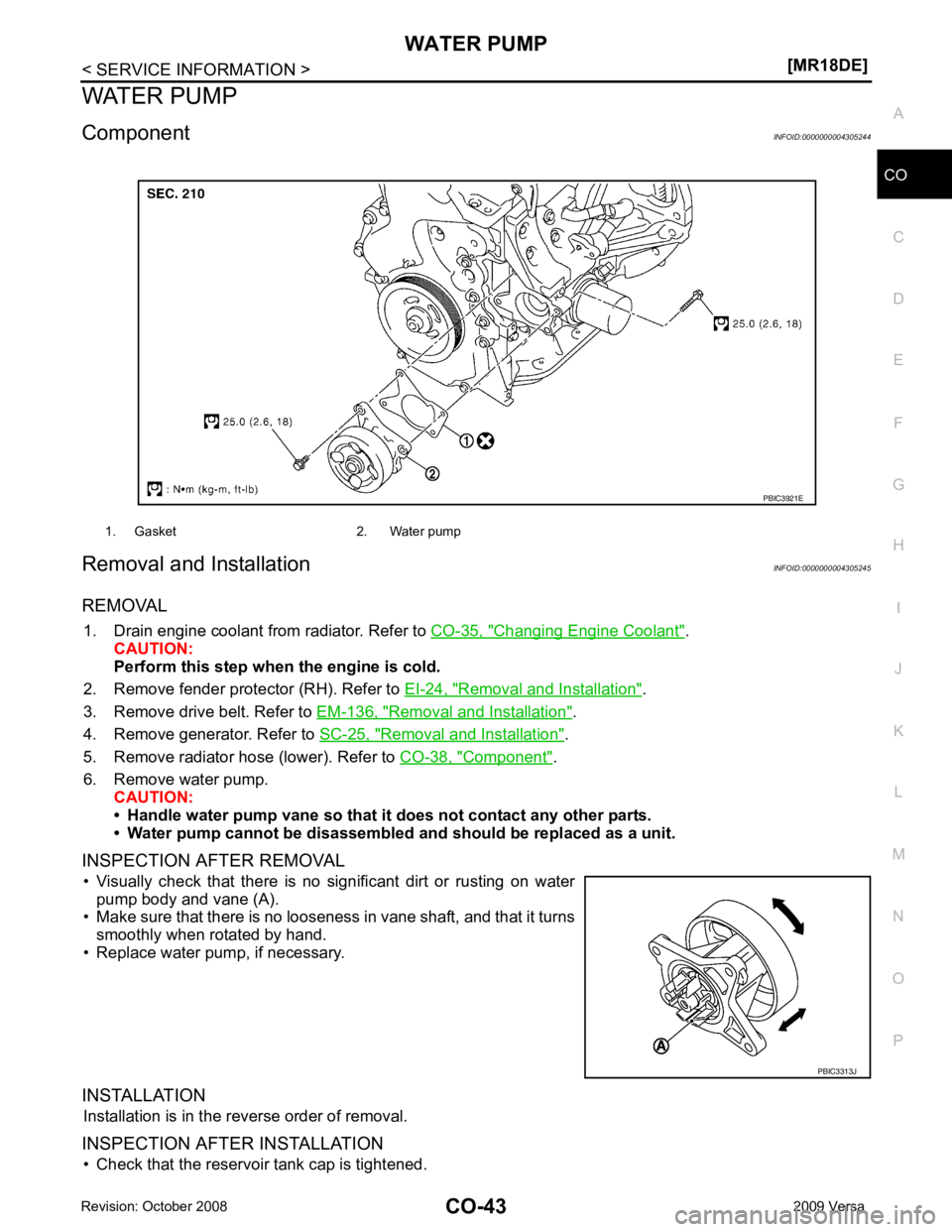
Component INFOID:0000000004305244
Removal and Installation INFOID:0000000004305245
REMOVAL 1. Drain engine coolant from radiator. Refer to CO-35, " Changing Engine Coolant " .
CAUTION:
Perform this step when the engine is cold.
2. Remove fender protector (RH). Refer to EI-24, " Removal and Installation " .
3. Remove drive belt. Refer to EM-136, " Removal and Installation " .
4. Remove generator. Refer to SC-25, " Removal and Installation " .
5. Remove radiator hose (lower). Refer to CO-38, " Component " .
6. Remove water pump. CAUTION:
• Handle water pump vane so that it does not contact any other parts.
• Water pump cannot be disassembled and should be replaced as a unit.
INSPECTION AFTER REMOVAL • Visually check that there is no significant dirt or rusting on water pump body and vane (A).
• Make sure that there is no looseness in vane shaft, and that it turns
smoothly when rotated by hand.
• Replace water pump, if necessary.
INSTALLATION Installation is in the reverse order of removal.
INSPECTION AFTER INSTALLATION • Check that the reservoir tank cap is tightened. 1. Gasket 2. Water pump
PBIC3313J
Page 1141 of 4331
![NISSAN LATIO 2009 Service Repair Manual CVT FLUID
CVT-197
< SERVICE INFORMATION >
[RE0F08B] D
E
F
G H
I
J
K L
M A
B CVT
N
O P
FLUID CONDITION CHECK
Changing CVT Fluid INFOID:0000000004305571
1. Warm up CVT fluid by driving the vehicle for 1 NISSAN LATIO 2009 Service Repair Manual CVT FLUID
CVT-197
< SERVICE INFORMATION >
[RE0F08B] D
E
F
G H
I
J
K L
M A
B CVT
N
O P
FLUID CONDITION CHECK
Changing CVT Fluid INFOID:0000000004305571
1. Warm up CVT fluid by driving the vehicle for 1](/manual-img/5/57359/w960_57359-1140.png)
CVT FLUID
CVT-197
< SERVICE INFORMATION >
[RE0F08B] D
E
F
G H
I
J
K L
M A
B CVT
N
O P
FLUID CONDITION CHECK
Changing CVT Fluid INFOID:0000000004305571
1. Warm up CVT fluid by driving the vehicle for 10 minutes.
• : Vehicle front
• Radiator (2)
• CVT fluid cooler hose [inlet side (3)]
• Transaxle assembly (4)
2. Drain CVT fluid from CVT fluid cooler hose [outlet side (1)] and refill with new specified NISSAN CVT fluid in the CVT fluid
charging pipe with the engine running at idle speed.
CAUTION:
Only use the specifi ed NISSAN CVT fluid.
3. Refill until new CVT fluid comes out from CVT fluid cooler hose [outlet side (1)]. NOTE:
About 30 to 50% extra fluid will be required for this procedure.
4. Check fluid level and condition. Refer to CVT-196, " Checking CVT Fluid " .
CAUTION:
Delete CVT fluid deterioration date with CO NSULT-III after changing CVT fluid. Refer to CVT-230," CONSULT-III Function (TRANSMISSION) " .
CVT Fluid Cooler Cleaning INFOID:0000000004305572
Whenever a CVT is repaired, overhauled, or replaced, t he CVT fluid cooler mounted in the radiator must be
inspected and cleaned.
Metal debris and friction material, if present, can be trapped or become deposit in the CVT fluid cooler. This
debris can contaminate the newly serviced CVT or, in severe cases, can block or restrict the flow of CVT fluid.
In either case, malfunction of the newly serviced CVT may occur.
Debris, if present, may deposit as CVT fluid enters the cool er inlet. It will be necessary to back flush the cooler
through the cooler outlet in order to flush out any built up debris.
CVT FLUID COOLER CLEANING PROCEDURE 1. Identify the CVT inlet and outlet fluid cooler hoses.
2. Position an oil pan under the inlet and outlet cooler hoses. Fluid status Conceivable cause Required operation
Varnished (viscous
varnish state) Clutch, brake
scorched Replace the CVT fluid and check the
CVT main unit and the vehicle for
malfunctions (wire harness, cooler
pipes, etc.)
Milky white or cloudy Water in the fluid Replace the CVT fluid and check for places where water is getting in.
Large amount of
metal powder mixed
in fluid Unusual wear of
sliding parts within
CVT Replace the CVT fluid and check for
improper operation of the CVT. ATA0022D
Fluid capacity and grade: Refer to
MA-14, " Fluids
and Lubricants " .
SCIA6088E
Page 1726 of 4331
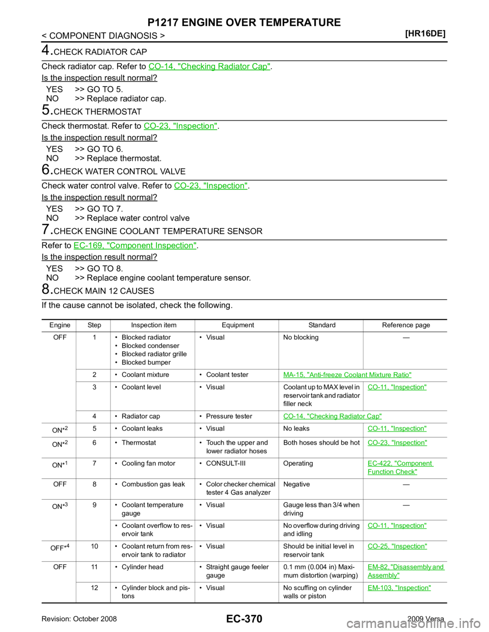
Checking Radiator Cap " .
Is the inspection result normal? YES >> GO TO 5.
NO >> Replace radiator cap. Inspection " .
Is the inspection result normal? YES >> GO TO 6.
NO >> Replace thermostat. Inspection " .
Is the inspection result normal? YES >> GO TO 7.
NO >> Replace water control valve Component Inspection " .
Is the inspection result normal? YES >> GO TO 8.
NO >> Replace engine coolant temperature sensor. Anti-freeze Coolant Mixture Ratio "
3 • Coolant level • Visual Coolant up to MAX level in
reservoir tank and radiator
filler neck CO-11, " Inspection "
4 • Radiator cap • Pressure tester
CO-14, " Checking Radiator Cap "
ON*
2
5 • Coolant leaks • Visual No leaks CO-11, " Inspection "
ON*
2
6 • Thermostat • Touch the upper and
lower radiator hosesBoth hoses should be hot
CO-23, " Inspection "
ON*
1
7 • Cooling fan motor • CONSULT-III Operating EC-422, " Component
Function Check "
OFF 8 • Combustion gas leak • Color checker chemical
tester 4 Gas analyzerNegative —
ON* 3
9 • Coolant temperature
gauge • Visual Gauge less than 3/4 when
driving —
• Coolant overflow to res- ervoir tank • Visual No overflow during driving
and idling CO-11, " Inspection "
OFF*
4
10 • Coolant return from res-
ervoir tank to radiator • Visual Should be initial level in
reservoir tank CO-25, " Inspection "
OFF 11 • Cylinder head • Straight gauge feeler
gauge0.1 mm (0.004 in) Maxi-
mum distortion (warping) EM-82, " Disassembly and
Assembly "
12 • Cylinder block and pis-
tons • Visual No scuffing on cylinder
walls or piston EM-103, " Inspection "
Page 1846 of 4331
Camshaft
EM-58Intake valve timing control
EM-49Intake valve
3EM-82 Exhaust valve
Exhaust Exhaust manifold/Tube/Muf- fler/Gasket 5 5 5 5 5 5 5 5 EM-31 EX-4
Three way catalyst
Lubrica-
tion Oil pan/Oil strainer/Oil pump/ Oil filter/Oil gallery/Oil cooler 5 5 5 5 5 5 5 5 EM-39 EM-42
LU-7
LU-9
Oil level (Low)/Filthy oil
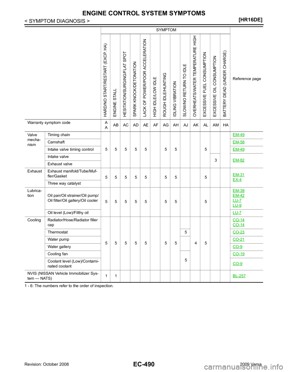
LU-7Cooling Radiator/Hose/Radiator filler
cap
5 5 5 5 5 5 5 4 5 CO-14 CO-14
Thermostat 5
CO-23Water pump
CO-21Water gallery
CO-9Cooling fan
5CO-19Coolant level (Low)/Contami-
nated coolant CO-9NVIS (NISSAN Vehicle Immobilizer Sys-
tem — NATS) 1 1
BL-257 SYMPTOM
Reference pageHARD/NO START/RESTART (EXCP. HA)
ENGINE STALL
HESITATION/SURGING/FLAT SPOT
SPARK KNOCK/DETONATION
LACK OF POWER/POOR ACCELERATION
HIGH IDLE/LOW IDLE
ROUGH IDLE/HUNTING
IDLING VIBRATION
SLOW/NO RETURN TO IDLE
OVERHEATS/WATER TEMPERATURE HIGH
EXCESSIVE FUEL CONSUMPTION
EXCESSIVE OIL CONSUMPTION
BATTERY DEAD (UNDER CHARGE)
Warranty symptom code A AAB AC AD AE AF AG AH AJ AK AL AM HA
Page 1943 of 4331
EC
NP
O
1 - 6: The numbers refer to the order of inspection.
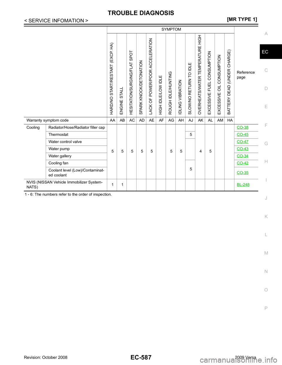
Cooling Radiator/Hose/Radiator filler cap
5 5 5 5 5 5 5 4 5 CO-38Thermostat
5CO-45 Water control valve
CO-47Water pump
CO-43Water gallery
CO-34Cooling fan
5CO-42 Coolant level (Low)/Contaminat-
ed coolant CO-35NVIS (NISSAN Vehicle
Immobilizer System-
NATS) 1 1
BL-248 SYMPTOM
Reference
pageHARD/NO START/RESTART (EXCP. HA)
ENGINE STALL
HESITATION/SURGING/FLAT SPOT
SPARK KNOCK/DETONATION
LACK OF POWER/POOR ACCELERATION
HIGH IDLE/LOW IDLE
ROUGH IDLE/HUNTING
IDLING VIBRATION
SLOW/NO RETURN TO IDLE
OVERHEATS/WATER TEMPERATURE HIGH
EXCESSIVE FUEL CONSUMPTION
EXCESSIVE OIL CONSUMPTION
BATTERY DEAD (UNDER CHARGE)
Warranty symptom code AA AB AC AD AE AF AG AH AJ AK AL AM HA
Page 2243 of 4331
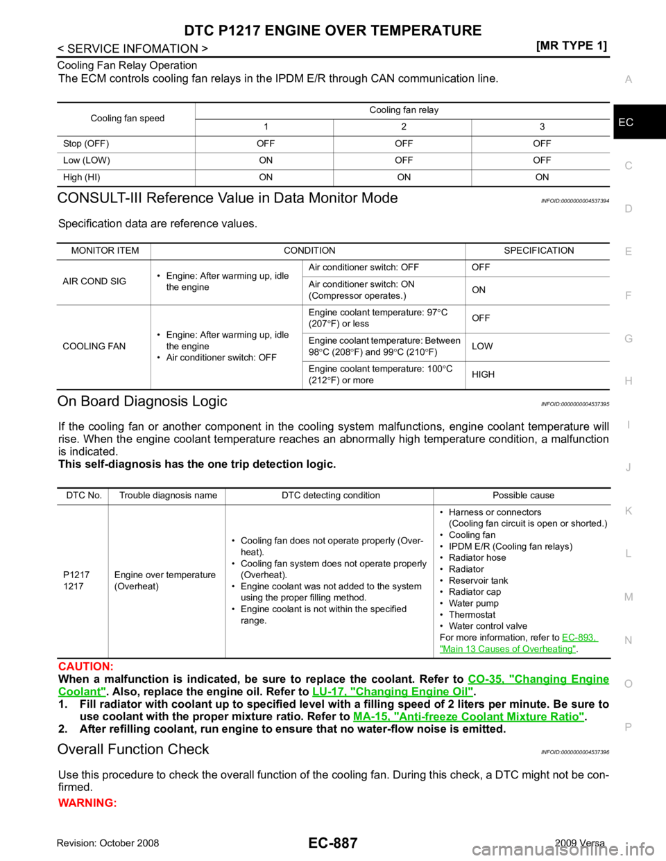
EC
NP
O
Cooling Fan Relay Operation
The ECM controls cooling fan relays in the IPDM E/R through CAN communication line.
CONSULT-III Reference Val ue in Data Monitor Mode INFOID:0000000004537394
Specification data are reference values.
On Board Diagnosis Logic INFOID:0000000004537395
If the cooling fan or another component in the cooli ng system malfunctions, engine coolant temperature will
rise. When the engine coolant temperature reaches an abnormally high temperature condition, a malfunction
is indicated.
This self-diagnosis has the on e trip detection logic.
CAUTION:
When a malfunction is in dicated, be sure to replace the coolant. Refer to CO-35, " Changing Engine
Coolant " . Also, replace the engine oil. Refer to
LU-17, " Changing Engine Oil " .
1. Fill radiator with coolant up to specified level with a filling speed of 2 liters per minute. Be sure to
use coolant with the proper mixture ratio. Refer to MA-15, " Anti-freeze Coolant Mixture Ratio " .
2. After refilling coolant, run engine to ensure that no water-flow noise is emitted.
Overall Function Check INFOID:0000000004537396
Use this procedure to check the overall function of the cooling fan. During this check, a DTC might not be con-
firmed.
WARNING: Cooling fan speed
Cooling fan relay
1 2 3
Stop (OFF) OFF OFF OFF
Low (LOW) ON OFF OFF
High (HI) ON ON ON MONITOR ITEM CONDITION SPECIFICATION
AIR COND SIG • Engine: After warming up, idle
the engine Air conditioner switch: OFF OFF
Air conditioner switch: ON
(Compressor operates.) ON
COOLING FAN • Engine: After warming up, idle
the engine
• Air conditioner switch: OFF Engine coolant temperature: 97
°C
(207 °F) or less OFF
Engine coolant temperature: Between
98 °C (208 °F) and 99 °C (210 °F) LOW
Engine coolant temperature: 100 °C
(212 °F) or more HIGHDTC No. Trouble diagnosis name DTC detecting condition Possible cause
P1217
1217 Engine over temperature
(Overheat) • Cooling fan does not operate properly (Over-
heat).
• Cooling fan system does not operate properly (Overheat).
• Engine coolant was not added to the system using the proper filling method.
• Engine coolant is not within the specified
range. • Harness or connectors
(Cooling fan circuit is open or shorted.)
• Cooling fan
• IPDM E/R (Cooling fan relays)
• Radiator hose
• Radiator
• Reservoir tank
• Radiator cap
• Water pump
• Thermostat
• Water control valve
For more information, refer to EC-893, " Main 13 Causes of Overheating " .
Page 2244 of 4331
![NISSAN LATIO 2009 Service Repair Manual EC-888< SERVICE INFOMATION >
[MR TYPE 1]
DTC P1217 ENGINE
OVER TEMPERATURE
Never remove the radiator cap when the engine is hot. Serious burns could be caused by high pres-
sure flui NISSAN LATIO 2009 Service Repair Manual EC-888< SERVICE INFOMATION >
[MR TYPE 1]
DTC P1217 ENGINE
OVER TEMPERATURE
Never remove the radiator cap when the engine is hot. Serious burns could be caused by high pres-
sure flui](/manual-img/5/57359/w960_57359-2243.png)
EC-888< SERVICE INFOMATION >
[MR TYPE 1]
DTC P1217 ENGINE
OVER TEMPERATURE
Never remove the radiator cap when the engine is hot. Serious burns could be caused by high pres-
sure fluid escaping from the reser voir tank or the radiator.
Wrap a thick cloth around cap. Carefully remove the cap by turning it a quarter turn to allow built-up
pressure to escape. Then turn the cap all the way off.
WITH CONSULT-III
1. Check the coolant level in the reservoir tank and radiator. Allow engine to cool before checking coolant level.
If the coolant level in the reservoir tank and/or radiator is below
the proper range, skip the following steps and go to EC-890," Diagnosis Procedure " or
EC-890, " Diagnosis Procedure " .
2. Confirm whether customer filled the coolant or not. If customer
filled the coolant, skip the following steps and go to EC-890," Diagnosis Procedure " or
EC-890, " Diagnosis Procedure " .
3. Turn ignition switch ON.
4. Perform “COOLING FAN” in “ACTIVE TEST” mode with CON- SULT-III.
5. If the results are NG, go to EC-890, " Diagnosis Procedure " or
EC-890, " Diagnosis Procedure " .
WITH GST
1. Check the coolant level in the reservoir tank and radiator. Allow engine to cool before checking coolant level.
If the coolant level in the reservoir tank and/or radiator is below
the proper range, skip the following steps and go to EC-890," Diagnosis Procedure " .
2. Confirm whether customer filled the coolant or not. If customer
filled the coolant, skip the following steps and go to EC-890," Diagnosis Procedure " .
3. Perform IPDM/ER auto active te st and check cooling fan motor
operation. Refer to PG-19, " Auto Active Test " .
4. If NG, go to EC-890, " Diagnosis Procedure " . SEF621W
SEF621W