2009 NISSAN LATIO wiring
[x] Cancel search: wiringPage 3838 of 4331
![NISSAN LATIO 2009 Service Repair Manual MT-44< SERVICE INFORMATION >
[RS6F94R]
PRECAUTIONS
SERVICE INFORMATION
PRECAUTIONS
Precaution for Supplemental Restraint Syst em (SRS) "AIR BAG" and "SEAT BELT
PRE-TENSIONER" INFOID:0000000004305264
NISSAN LATIO 2009 Service Repair Manual MT-44< SERVICE INFORMATION >
[RS6F94R]
PRECAUTIONS
SERVICE INFORMATION
PRECAUTIONS
Precaution for Supplemental Restraint Syst em (SRS) "AIR BAG" and "SEAT BELT
PRE-TENSIONER" INFOID:0000000004305264](/manual-img/5/57359/w960_57359-3837.png)
MT-44< SERVICE INFORMATION >
[RS6F94R]
PRECAUTIONS
SERVICE INFORMATION
PRECAUTIONS
Precaution for Supplemental Restraint Syst em (SRS) "AIR BAG" and "SEAT BELT
PRE-TENSIONER" INFOID:0000000004305264
The Supplemental Restraint System such as “A IR BAG” and “SEAT BELT PRE-TENSIONER”, used along
with a front seat belt, helps to reduce the risk or severi ty of injury to the driver and front passenger for certain
types of collision. This system includes seat belt switch inputs and dual stage front air bag modules. The SRS
system uses the seat belt switches to determine the front air bag deployment, and may only deploy one front
air bag, depending on the severity of a collision and w hether the front occupants are belted or unbelted.
Information necessary to service the system safely is included in the SRS and SB section of this Service Man-
ual.
WARNING:
• To avoid rendering the SRS inopera tive, which could increase the risk of personal injury or death in
the event of a collision which would result in air bag inflation, all maintenance must be performed by
an authorized NISS AN/INFINITI dealer.
• Improper maintenance, including in correct removal and installation of the SRS, can lead to personal
injury caused by unintent ional activation of the system. For re moval of Spiral Cable and Air Bag
Module, see the SRS section.
• Do not use electrical test equipmen t on any circuit related to the SRS unless instructed to in this
Service Manual. SRS wiring harn esses can be identified by yellow and/or orange harnesses or har-
ness connectors.
Precaution for Procedure without Cowl Top Cover INFOID:0000000004305265
When performing the procedure after removing cowl top cover, cover
the lower end of windshield with urethane, etc.
Precaution INFOID:0000000004305266
• If transaxle assembly is removed from the vehi cle, always replace CSC (Concentric Slave Cylinder).
Installed CSC returns to the original position when removing transaxle assembly. Dust on clutch disc sliding
parts may damage CSC seal, and may cause clutch fluid leakage.
• Do not reuse transaxle oil.
• Drain, fill and check transaxle oil with the vehicle on level surface.
• During removal or installation, keep inside of transaxle clear of dust or dirt.
• Check for the correct installation orientation prior to removal or disassembly. If matching marks are required,
be certain they do not interfere with the f unction of the parts they are applied to.
• In principle, tighten bolts or nuts gradually in several steps working diagonally from inside to outside. If tight-
ening sequence is specified, follow it.
• Be careful not to damage the sliding surfaces and mating surfaces of parts. PIIB3706J
Page 3886 of 4331

MTC
N
O P
CONTENTS
MANUAL AIR CONDITIONER
SERVICE INFORMATION .. ..........................3
PRECAUTIONS .............................................. .....3
Precaution for Supplemental Restraint System
(SRS) "AIR BAG" and "SEAT BELT PRE-TEN-
SIONER" ............................................................. ......
3
Precaution Necessary fo r Steering Wheel Rota-
tion After Battery Disconnect ............................... ......
3
Precaution for Procedure without Cowl Top Cover ......4
Precaution for Working with HFC-134a (R-134a) ......4
General Refrigerant Precaution .......................... ......4
Oil Precaution ...................................................... ......5
Precaution for Refrigeran t Connection ......................5
Precaution for Service of Compressor ................ ......7
Precaution for Service Equipment ....................... ......8
Precaution for Leak Detection Dye ..................... ......9
PREPARATION .............................................. ....11
HFC-134a (R-134a) Service Tool and Equipment ....11
Commercial Service Tool .................................... ....13
REFRIGERATION SYSTEM .......................... ....15
Refrigerant Cycle ................................................ ....15
Refrigerant System Protec tion ................................15
Component Part Location ................................... ....16
OIL .................................................................. ....17
Maintenance of Oil Quantity in Compressor ....... ....17
AIR CONDITIONER CONTROL ..................... ....19
Control Operation ................................................ ....19
Discharge Air Flow .............................................. ....20
System Description ............................................. ....20
TROUBLE DIAGNOSIS ................................. ....22
CONSULT-II Function (BCM) .............................. ....22
How to Perform Trouble Diagnosis for Quick and
Accurate Repair ........... ...........................................
22
Component Parts and Harness Connector Loca-
tion ...................................................................... ....
23
Schematic ........................................................... ....25
Wiring Diagram - Heater - ................................... ....26 Wiring Diagram - A/C,M - ....................................
....27
Operational Check ............................................... ....30
Mode Door ........................................................... ....31
Air Mix Door ......................................................... ....32
Intake Door .......................................................... ....33
Front Blower Motor Circuit .......................................33
Magnet Clutch Circuit (If Equipped) ..................... ....37
Insufficient Cooling .............................................. ....45
Insufficient Heating .............................................. ....52
Noise ................................................................... ....53
CONTROLLER .................................................. 55
Removal and Installation ..................................... ....55
Disassembly and Assembly ................................. ....56
THERMO CONTROL AMPLIFIER .................... 57
Removal and Installation ..................................... ....57
A/C UNIT ASSEMBLY ...................................... 58
Removal and Installation ..................................... ....58
Disassembly and Assembly ................................. ....60
BLOWER MOTOR ............................................ 62
Removal and Installation ..................................... ....62
INTAKE DOOR .................................................. 63
Intake Door Cable Adjustment ............................. ....63
AIR MIX DOOR ................................................. 64
Air Mix Door Cable Adjustment ........................... ....64
MODE DOOR .................................................... 65
Mode Door Cable Adjustment ............................. ....65
BLOWER FAN RESISTOR ............................... 66
Removal and Installation ..................................... ....66
HEATER CORE ................................................. 67
Removal and Installation ..................................... ....67
AIR CONDITIONER FILTER ............................. 68
Removal and Installation ..................................... ....68
Page 3888 of 4331
MTC
N
O P
SERVICE INFORMATION
PRECAUTIONS
Precaution for Supplemental Restraint System (SRS) "AIR BAG" and "SEAT BELT
PRE-TENSIONER" INFOID:0000000004784399
The Supplemental Restraint System such as “A IR BAG” and “SEAT BELT PRE-TENSIONER”, used along
with a front seat belt, helps to reduce the risk or severi ty of injury to the driver and front passenger for certain
types of collision. This system includes seat belt switch inputs and dual stage front air bag modules. The SRS
system uses the seat belt switches to determine the front air bag deployment, and may only deploy one front
air bag, depending on the severity of a collision and w hether the front occupants are belted or unbelted.
Information necessary to service the system safely is included in the SRS and SB section of this Service Man-
ual.
WARNING:
• To avoid rendering the SRS inoper ative, which could increase the risk of personal injury or death in
the event of a collision which would result in air bag inflation, all maintenance must be performed by
an authorized NISSAN/INFINITI dealer.
• Improper maintenance, including in correct removal and installation of the SRS can lead to personal
injury caused by unintentional act ivation of the system. For removal of Spiral Cable and Air Bag
Module, see the SRS section.
• Do not use electrical test equipm ent on any circuit related to the SRS unless instructed to in this
Service Manual. SRS wiring harnesses can be identi fied by yellow and/or orange harnesses or har-
ness connectors.
PRECAUTIONS WHEN USING POWER TOOLS (AIR OR ELECTRIC) AND HAMMERS WARNING:
• When working near the Airbag Diagnosis Sensor Un it or other Airbag System sensors with the Igni-
tion ON or engine running, DO NOT use air or el ectric power tools or strike near the sensor(s) with a
hammer. Heavy vibration could activate the sensor( s) and deploy the air bag(s), possibly causing
serious injury.
• When using air or electric power tools or hammers , always switch the Ignition OFF, disconnect the
battery, and wait at least 3 minutes before performing any service.
Precaution Necessary for Steering Wh eel Rotation After Battery Disconnect
INFOID:0000000004687764
NOTE:
• This Procedure is applied only to models with Inte lligent Key system and NATS (NISSAN ANTI-THEFT SYS-
TEM).
• Remove and install all control units after disconnecti ng both battery cables with the ignition knob in the
″ LOCK ″ position.
• Always use CONSULT-III to perform self-diagnosis as a part of each function inspection after finishing work.
If DTC is detected, perform trouble diagnosis according to self-diagnostic results.
For models equipped with the Intelligent Key system and NATS , an electrically controlled steering lock mech-
anism is adopted on the key cylinder.
For this reason, if the battery is disconnected or if the battery is discharged, the steering wheel will lock and
steering wheel rotation will become impossible.
If steering wheel rotation is required when battery pow er is interrupted, follow the procedure below before
starting the repair operation.
OPERATION PROCEDURE 1. Connect both battery cables. NOTE:
Supply power using jumper cables if battery is discharged.
2. Use the Intelligent Key or mechanical key to turn the ignition switch to the ″ACC ″ position. At this time, the
steering lock will be released.
3. Disconnect both battery cables. The steering lock will remain released and the steering wheel can be
rotated.
4. Perform the necessary repair operation.
Page 3912 of 4331
MTC
N
O P
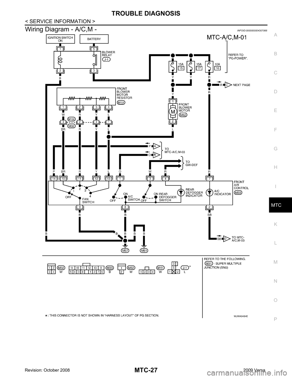
Wiring Diagram - A/C,M -
INFOID:0000000004307066
Page 3984 of 4331

PG
N
O P
CONTENTS
POWER SUPPLY, GROUND & CIRCUIT ELEMENTS
SERVICE INFORMATION .. ..........................2
PRECAUTIONS .............................................. .....2
Precaution for Supplemental Restraint System
(SRS) "AIR BAG" and "SEAT BELT PRE-TEN-
SIONER" ............................................................. ......
2
POWER SUPPLY ROUTING CIRCUIT .......... .....3
Schematic ........................................................... ......3
Wiring Diagram - POWER - ................................ ......5
Fuse .................................................................... ....15
Fusible Link ......................................................... ....15
Circuit Breaker (Built Into BCM) .......................... ....15
Circuit Breaker .................................................... ....15
IPDM E/R (INTELLIGENT POWER DISTRI-
BUTION MODULE ENGINE ROOM) ............. ....16
System Description ............................................. ....16
CAN Communication System Description ........... ....17
Function of Detecting Igni tion Relay Malfunction ....17
CONSULT-III Function (IPDM E/R) ..................... ....17
Auto Active Test .................................................. ....19
IPDM E/R Terminal Arrangement - Type A ......... ....22
IPDM E/R Terminal Arrangement - Type B ......... ....23
Terminal and Reference Value for IPDM E/R ..... ....24
IPDM E/R Power/Ground Circuit Inspection ....... ....26
Inspection with CONSULT- III (Self-Diagnosis) .......27
Removal and Installation of IPDM E/R ....................27 GROUND CIRCUI
T ........................................... 29
Ground Distribution .............................................. ....29
HARNESS ................... ...................................... 38
Harness Layout ................................................... ....38
Wiring Diagram Codes (Cell Codes) ................... ....57
ELECTRICAL UNITS LOCATION .................... 60
Electrical Units Location ...................................... ....60
HARNESS CONNECTOR ................................. 64
Description ........................................................... ....64
ELECTRICAL UNITS ........................................ 67
Terminal Arrangement ......................................... ....67
STANDARDIZED RELAY ................................. 68
Description ........................................................... ....68
SUPER MULTIPLE JUNCTION (SMJ) ............. 70
Terminal Arrangement ......................................... ....70
FUSE BLOCK-JUNCTION BOX (J/B) .............. 72
Terminal Arrangement ......................................... ....72
FUSE AND FUSIBLE LINK BOX ...................... 73
Terminal Arrangement ......................................... ....73
Page 3988 of 4331
PG
N
O P
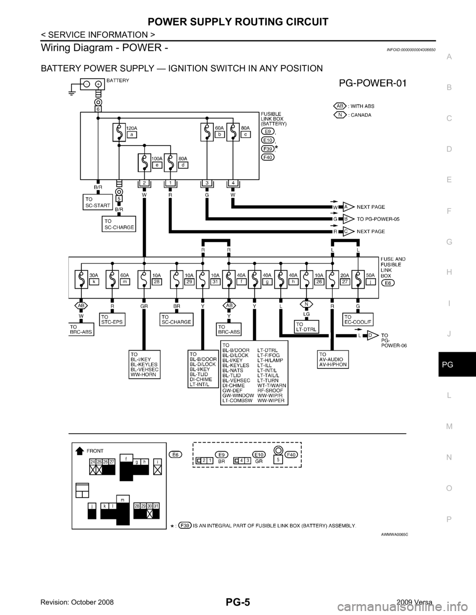
Wiring Diagram - POWER -
INFOID:0000000004306650
BATTERY POWER SUPPLY — IGNITION SWITCH IN ANY POSITION G
Page 3998 of 4331
PG
N
O P
Fuse
INFOID:0000000004306651
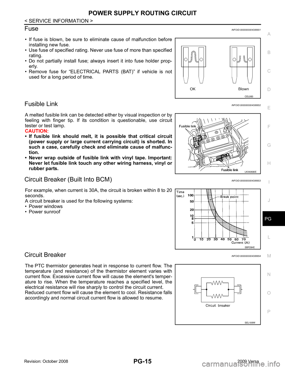
• If fuse is blown, be sure to eliminate cause of malfunction before installing new fuse.
• Use fuse of specified rating. Never use fuse of more than specified
rating.
• Do not partially install fuse; always insert it into fuse holder prop- erly.
• Remove fuse for “ELECTRICAL PARTS (BAT)” if vehicle is not
used for a long period of time.
Fusible Link INFOID:0000000004306652
A melted fusible link can be detected either by visual inspection or by
feeling with finger tip. If its condition is questionable, use circuit
tester or test lamp.
CAUTION:
• If fusible link should melt, it is possible that critical circuit
(power supply or large current carrying circuit) is shorted. In
such a case, carefully check and eliminate cause of malfunc-
tion.
• Never wrap outside of fusible li nk with vinyl tape. Important:
Never let fusible link touch any other wiring harness, vinyl or
rubber parts.
Circuit Breaker (B uilt Into BCM) INFOID:0000000004306653
For example, when current is 30A, the circuit is broken within 8 to 20
seconds.
A circuit breaker is used for the following systems:
• Power windows
• Power sunroof
Circuit Breaker INFOID:0000000004306654
The PTC thermistor generates heat in response to current flow. The
temperature (and resistance) of t he thermistor element varies with
current flow. Excessive current flow will cause the element's temper-
ature to rise. When the temperature reaches a specified level, the
electrical resistance will rise shar ply to control the circuit current.
Reduced current flow will cause the element to cool. Resistance falls
accordingly and normal circuit current flow is allowed to resume. LKIA0830E
SEL109W
Page 4006 of 4331
PG
N
O P
IPDM E/R Terminal Ar
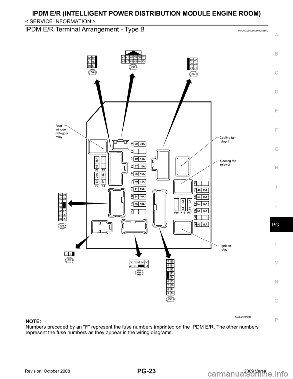
rangement - Type B INFOID:0000000004306660
NOTE:
Numbers preceded by an "F" represent the fuse number s imprinted on the IPDM E/R. The other numbers
represent the fuse numbers as they appear in the wiring diagrams.