2009 NISSAN LATIO wiring
[x] Cancel search: wiringPage 3270 of 4331
GI
N
O P
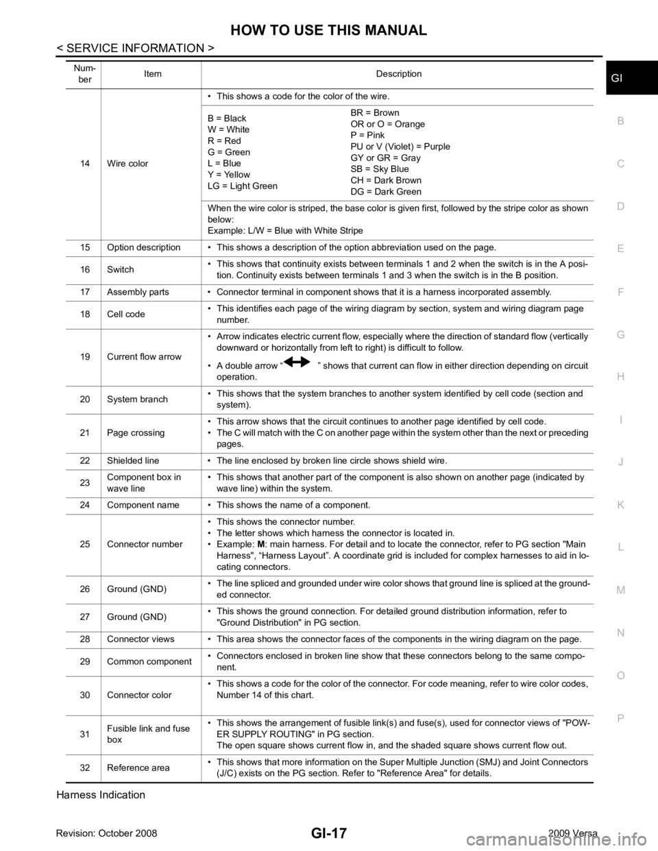
Harness Indication 14 Wire color
• This shows a code for the color of the wire.
B = Black
W = White
R = Red
G = Green
L = Blue
Y = Yellow
LG = Light Green BR = Brown
OR or O = Orange
P = Pink
PU or V (Violet) = Purple
GY or GR = Gray
SB = Sky Blue
CH = Dark Brown
DG = Dark Green
When the wire color is striped, the base color is given first, followed by the stripe color as shown
below:
Example: L/W = Blue with White Stripe
15 Option description • This shows a description of the option abbreviation used on the page.
16 Switch • This shows that continuity exists between terminals 1 and 2 when the switch is in the A posi-
tion. Continuity exists between terminals 1 and 3 when the switch is in the B position.
17 Assembly parts • Connector terminal in component shows that it is a harness incorporated assembly.
18 Cell code • This identifies each page of the wiring diagram by section, system and wiring diagram page
number.
19 Current flow arrow • Arrow indicates electric current flow, especially where the direction of standard flow (vertically
downward or horizontally from left to right) is difficult to follow.
• A double arrow “ ” shows that current can flow in either direction depending on circuit operation.
20 System branch • This shows that the system branches to another system identified by cell code (section and
system).
21 Page crossing • This arrow shows that the circuit continues to another page identified by cell code.
• The C will match with the C on another page within the system other than the next or preceding pages.
22 Shielded line • The line enclosed by broken line circle shows shield wire.
23 Component box in
wave line • This shows that another part of the component is also shown on another page (indicated by
wave line) within the system.
24 Component name • This shows the name of a component.
25 Connector number • This shows the connector number.
• The letter shows which harness the connector is located in.
• Example: M: main harness. For detail and to locate the connector, refer to PG section "Main
Harness", “Harness Layout”. A coordinate grid is included for complex harnesses to aid in lo-
cating connectors.
26 Ground (GND) • The line spliced and grounded under wire color shows that ground line is spliced at the ground-
ed connector.
27 Ground (GND) • This shows the ground connection. For detailed ground distribution information, refer to
"Ground Distribution" in PG section.
28 Connector views • This area shows the connector faces of the components in the wiring diagram on the page.
29 Common component • Connectors enclosed in broken line show that these connectors belong to the same compo-
nent.
30 Connector color • This shows a code for the color of the connector. For code meaning, refer to wire color codes,
Number 14 of this chart.
31 Fusible link and fuse
box • This shows the arrangement of fusible link(s) and fuse(s), used for connector views of "POW-
ER SUPPLY ROUTING" in PG section.
The open square shows current flow in, and the shaded square shows current flow out.
32 Reference area • This shows that more information on the Super Multiple Junction (SMJ) and Joint Connectors
(J/C) exists on the PG section. Refer to "Reference Area" for details.
Num-
ber Item Description
Page 3271 of 4331
GI-18< SERVICE INFORMATION >
HOW TO USE THIS MANUAL
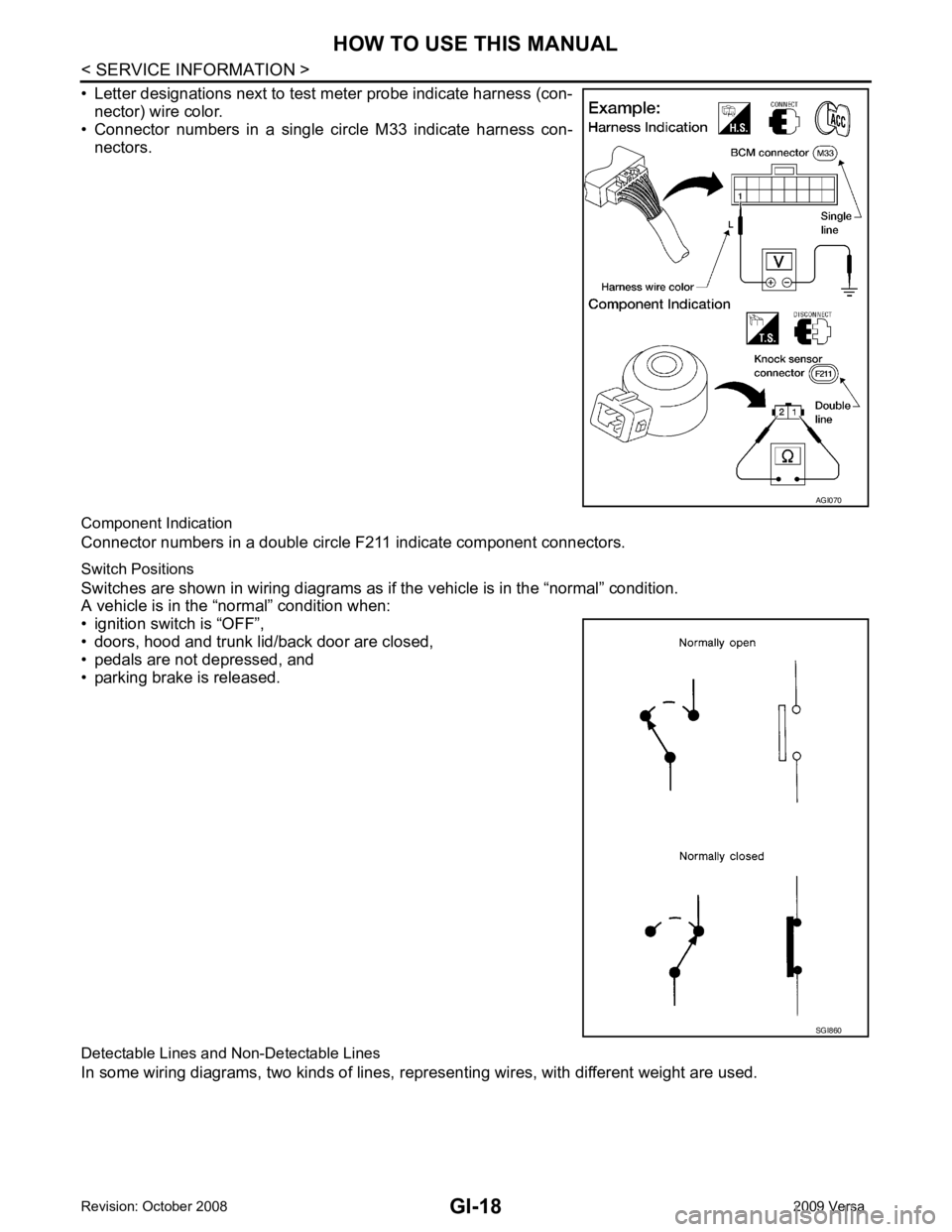
• Letter designations next to test meter probe indicate harness (con- nector) wire color.
• Connector numbers in a single circle M33 indicate harness con-
nectors.
Component Indication
Connector numbers in a double circle F211 indicate component connectors.
Switch Positions
Switches are shown in wiring diagrams as if the vehicle is in the “normal” condition.
A vehicle is in the “normal” condition when:
• ignition switch is “OFF”,
• doors, hood and trunk lid/back door are closed,
• pedals are not depressed, and
• parking brake is released.
Detectable Lines and Non-Detectable Lines
In some wiring diagrams, two kinds of lines, r epresenting wires, with different weight are used. AGI070
SGI860
Page 3272 of 4331
GI
N
O P
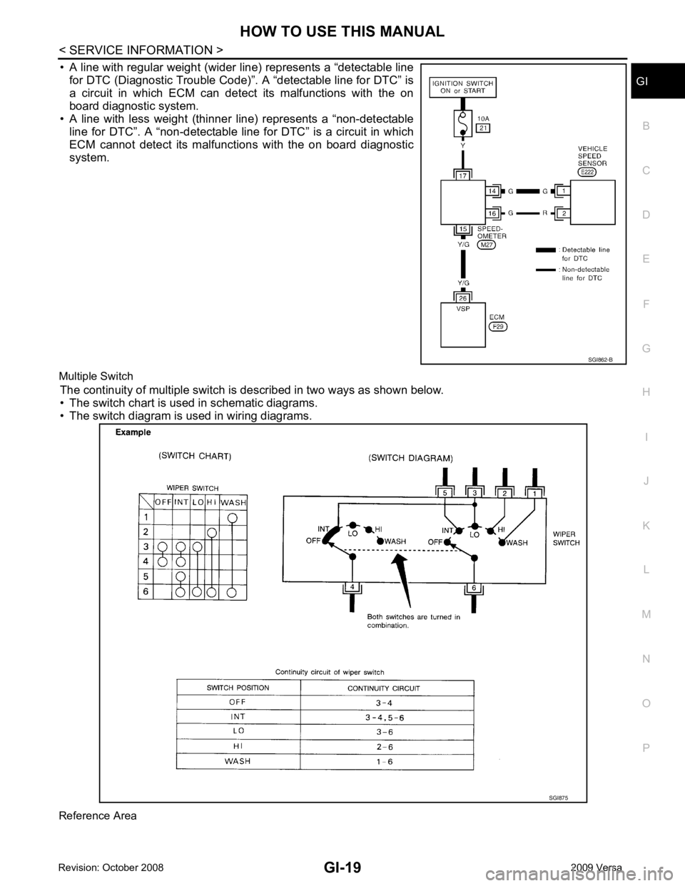
• A line with regular weight (wider line) represents a “detectable line
for DTC (Diagnostic Trouble Code)”. A “detectable line for DTC” is
a circuit in which ECM can detect its malfunctions with the on
board diagnostic system.
• A line with less weight (thinner line) represents a “non-detectable line for DTC”. A “non-detectable line for DTC” is a circuit in which
ECM cannot detect its malfunctions with the on board diagnostic
system.
Multiple Switch The continuity of multiple switch is described in two ways as shown below.
• The switch chart is used in schematic diagrams.
• The switch diagram is used in wiring diagrams.
Reference Area SGI875
Page 3280 of 4331
GI
N
O P
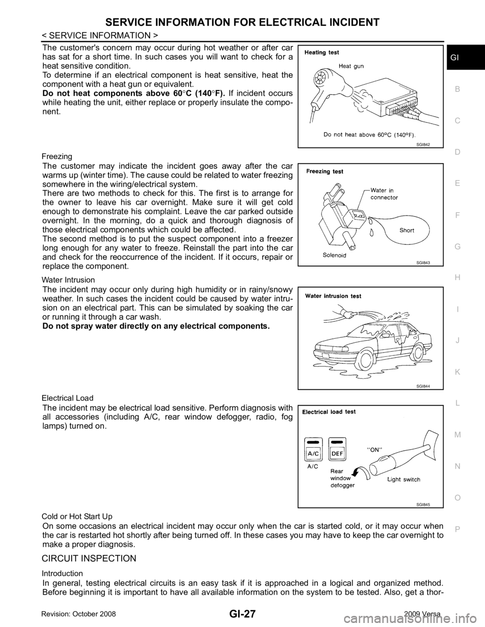
The customer's concern may occur during hot weather or after car
has sat for a short time. In such cases you will want to check for a
heat sensitive condition.
To determine if an electrical com ponent is heat sensitive, heat the
component with a heat gun or equivalent.
Do not heat components above 60 °C (140 °F). If incident occurs
while heating the unit, either replace or properly insulate the compo-
nent.
Freezing The customer may indicate the incident goes away after the car
warms up (winter time). The cause could be related to water freezing
somewhere in the wiring/electrical system.
There are two methods to check for this. The first is to arrange for
the owner to leave his car overnight. Make sure it will get cold
enough to demonstrate his complaint. Leave the car parked outside
overnight. In the morning, do a quick and thorough diagnosis of
those electrical components which could be affected.
The second method is to put the suspect component into a freezer
long enough for any water to freeze. Reinstall the part into the car
and check for the reoccurrence of the incident. If it occurs, repair or
replace the component.
Water Intrusion The incident may occur only during high humidity or in rainy/snowy
weather. In such cases the incident could be caused by water intru-
sion on an electrical part. This c an be simulated by soaking the car
or running it through a car wash.
Do not spray water directly on any electrical components.
Electrical Load The incident may be electrical load sensitive. Perform diagnosis with
all accessories (including A/C, rear window defogger, radio, fog
lamps) turned on.
Cold or Hot Start Up On some occasions an electrical incident may occur only when the car is started cold, or it may occur when
the car is restarted hot shortly after being turned off. In these cases you may have to keep the car overnight to
make a proper diagnosis.
CIRCUIT INSPECTION
Introduction In general, testing electrical circuits is an easy ta sk if it is approached in a logical and organized method.
Before beginning it is important to have all available in formation on the system to be tested. Also, get a thor- SGI843
SGI845
Page 3290 of 4331
GI
N
O P
NOTE:
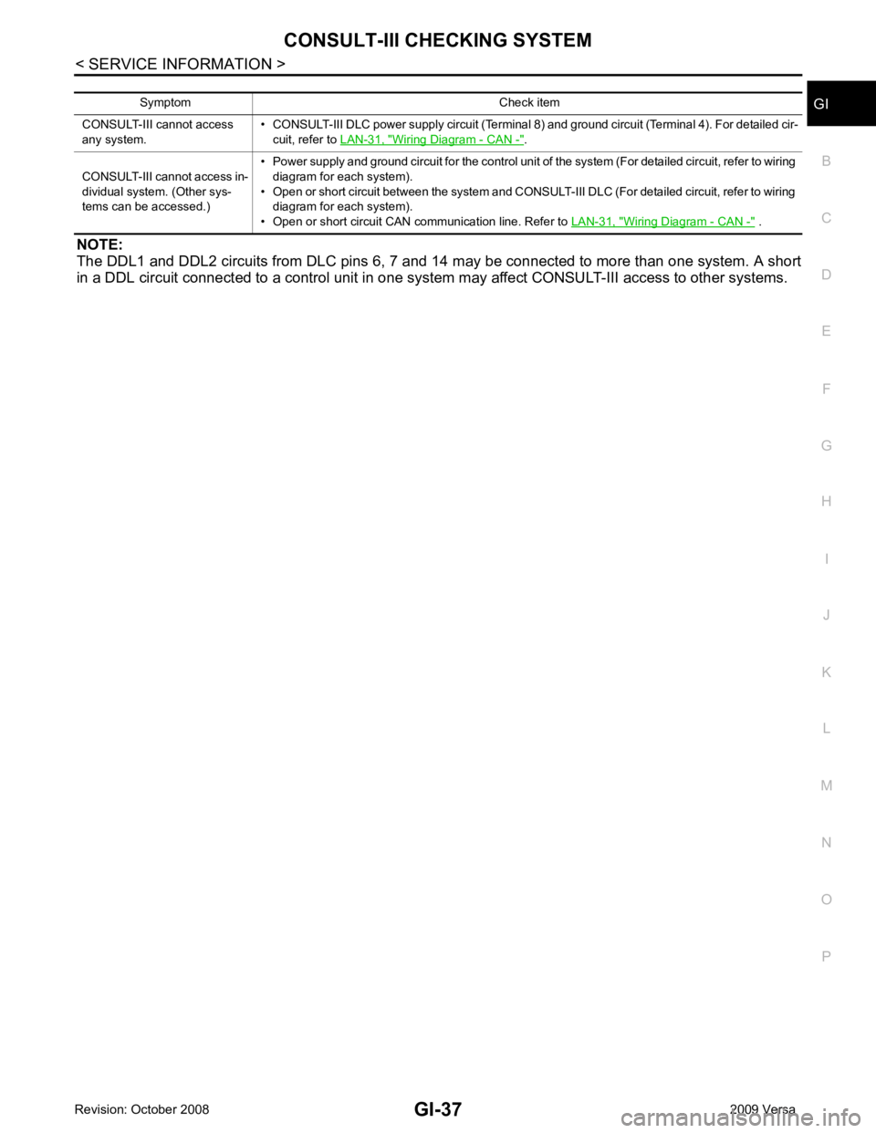
The DDL1 and DDL2 circuits from DLC pins 6, 7 and 14 may be connected to more than one system. A short
in a DDL circuit connected to a control unit in one syst em may affect CONSULT-III access to other systems.
Symptom Check item
CONSULT-III cannot access
any system. • CONSULT-III DLC power supply circuit (Terminal 8) and ground circuit (Terminal 4). For detailed cir-
cuit, refer to LAN-31, " Wiring Diagram - CAN - " .
CONSULT-III cannot access in-
dividual system. (Other sys-
tems can be accessed.) • Power supply and ground circuit for the control unit of the system (For detailed circuit, refer to wiring
diagram for each system).
• Open or short circuit between the system and CONSULT-III DLC (For detailed circuit, refer to wiring diagram for each system).
• Open or short circuit CAN communication line. Refer to LAN-31, " Wiring Diagram - CAN - " .
Page 3304 of 4331

GW
N
O P
CONTENTS
GLASSES, WINDOW SYSTEM & MIRRORS
SERVICE INFORMATION .. ..........................3
PRECAUTIONS .............................................. .....3
Precaution for Supplemental Restraint System
(SRS) "AIR BAG" and "SEAT BELT PRE-TEN-
SIONER" ............................................................. ......
3
Precaution Necessary fo r Steering Wheel Rota-
tion After Battery Disconnect ............................... ......
3
Precaution for Procedure without Cowl Top Cover ......4
Handling for Adhesive and Primer ...................... ......4
PREPARATION .............................................. .....5
Commercial Service Tool .................................... ......5
SQUEAK AND RATTLE TROUBLE DIAG-
NOSES ........................ ........................................6
Work Flow ........................................................... ......6
Generic Squeak and Rattle Troubleshooting ...... ......8
Diagnostic Worksheet ......................................... ....10
WINDSHIELD GLASS .................................... ....12
Removal and Installation .........................................12
OPERA WINDOW GLASS ............................. ....14
Removal and Installation .........................................14
REAR WINDOW GLASS AND MOLDING ..... ....16
Removal and Installation .........................................16
POWER WINDOW SYST EM ..............................19
Component Parts and Harness Connector Loca-
tion ...................................................................... ....
19
System Description ............................................. ....19
CAN Communication System Description ........... ....23
Schematic ........................................................... ....24
Wiring Diagram - WINDOW- ............................... ....25
Main Power Window and Door Lock/Unlock
Switch Harness Connector Terminal Layout ....... ....
29
Terminal and Reference Value for Main Power
Window and Door Lock/Unlock Switch ............... ....
29
Terminal and Reference Value for BCM ............. ....30
Work Flow ........................................................... ....30 CONSULT-III Function (B
CM) .................................30
Power Window Auto Operat ion Initialization ............31
Trouble Diagnosis Symptom Chart ...................... ....31
BCM Power Supply and Ground Circuit Inspection ....32
Main Power Window and Door Lock/Unlock
Switch Power Supply and Ground Circuit Inspec-
tion ....................................................................... ....
32
Front Power Window Motor LH Circuit Inspection ....33
Front Power Window RH Circuit Inspection (Pow-
er Window and Door Lock/Unlock Switch RH Op-
eration) ................................................................ ....
34
Front Power Window Motor RH Circuit Inspection ....34
Encoder Circuit Inspection ................................... ....36
Door Switch Check .............................................. ....38
Rear Power Window LH Circuit Inspection (Rear
Power Window Switch LH Operation) ................. ....
39
Rear Power Window RH Circu it Inspection (Rear
Power Window Switch RH Operation) ................. ....
40
Rear Power Window Motor LH Circuit Inspection ....40
Rear Power Window Motor RH Circuit Inspection ....42
FRONT DOOR GLASS AND REGULATOR ..... 44
Removal and Installation ..................................... ....44
Disassembly and Assembly ................................. ....46
Inspection after Installati on ......................................46
REAR DOOR GLASS AND REGULATOR ....... 48
Removal and Installation ..................................... ....48
Disassembly and Assembly ................................. ....50
Inspection after Installati on ......................................50
REAR WINDOW DEFOGGER .......................... 51
Component Parts and Harness Connector Loca-
tion ....................................................................... ....
51
System Description .............................................. ....51
CAN Communication System Description ........... ....52
Wiring Diagram - DEF - ....................................... ....53
Terminal and Reference Value for BCM ..................55
Terminal and Reference Va lue for IPDM E/R ..........55
Work Flow ............................................................ ....55
Page 3306 of 4331
GW
N
O P
SERVICE INFORMATION
PRECAUTIONS
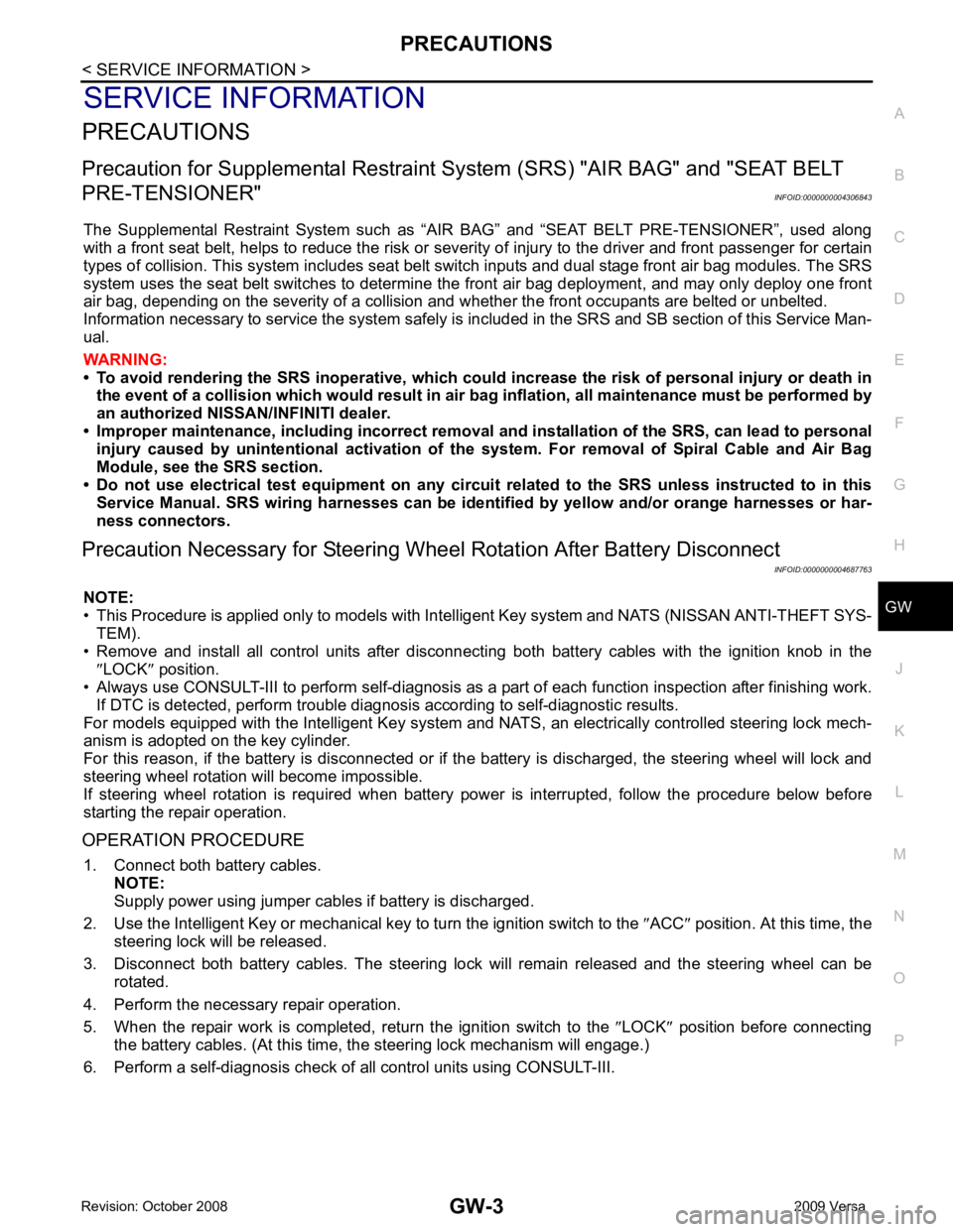
Precaution for Supplemental Restraint System (SRS) "AIR BAG" and "SEAT BELT
PRE-TENSIONER" INFOID:0000000004306843
The Supplemental Restraint System such as “A IR BAG” and “SEAT BELT PRE-TENSIONER”, used along
with a front seat belt, helps to reduce the risk or severi ty of injury to the driver and front passenger for certain
types of collision. This system includes seat belt switch inputs and dual stage front air bag modules. The SRS
system uses the seat belt switches to determine the front air bag deployment, and may only deploy one front
air bag, depending on the severity of a collision and w hether the front occupants are belted or unbelted.
Information necessary to service the system safely is included in the SRS and SB section of this Service Man-
ual.
WARNING:
• To avoid rendering the SRS inoper ative, which could increase the risk of personal injury or death in
the event of a collision which would result in air bag inflation, all maintenance must be performed by
an authorized NISSAN/INFINITI dealer.
• Improper maintenance, including in correct removal and installation of the SRS, can lead to personal
injury caused by unintentional act ivation of the system. For removal of Spiral Cable and Air Bag
Module, see the SRS section.
• Do not use electrical test equipm ent on any circuit related to the SRS unless instructed to in this
Service Manual. SRS wiring harnesses can be identi fied by yellow and/or orange harnesses or har-
ness connectors.
Precaution Necessary for Steering Wh eel Rotation After Battery Disconnect
INFOID:0000000004687763
NOTE:
• This Procedure is applied only to models with Inte lligent Key system and NATS (NISSAN ANTI-THEFT SYS-
TEM).
• Remove and install all control units after disconnecti ng both battery cables with the ignition knob in the
″ LOCK ″ position.
• Always use CONSULT-III to perform self-diagnosis as a part of each function inspection after finishing work.
If DTC is detected, perform trouble diagnosis according to self-diagnostic results.
For models equipped with the Intelligent Key system and NATS , an electrically controlled steering lock mech-
anism is adopted on the key cylinder.
For this reason, if the battery is disconnected or if the battery is discharged, the steering wheel will lock and
steering wheel rotation will become impossible.
If steering wheel rotation is required when battery pow er is interrupted, follow the procedure below before
starting the repair operation.
OPERATION PROCEDURE 1. Connect both battery cables. NOTE:
Supply power using jumper cables if battery is discharged.
2. Use the Intelligent Key or mechanical key to turn the ignition switch to the ″ACC ″ position. At this time, the
steering lock will be released.
3. Disconnect both battery cables. The steering lock will remain released and the steering wheel can be
rotated.
4. Perform the necessary repair operation.
5. When the repair work is completed, return the ignition switch to the ″LOCK ″ position before connecting
the battery cables. (At this time, the steering lock mechanism will engage.)
6. Perform a self-diagnosis check of al l control units using CONSULT-III.
Page 3328 of 4331
GW
N
O P
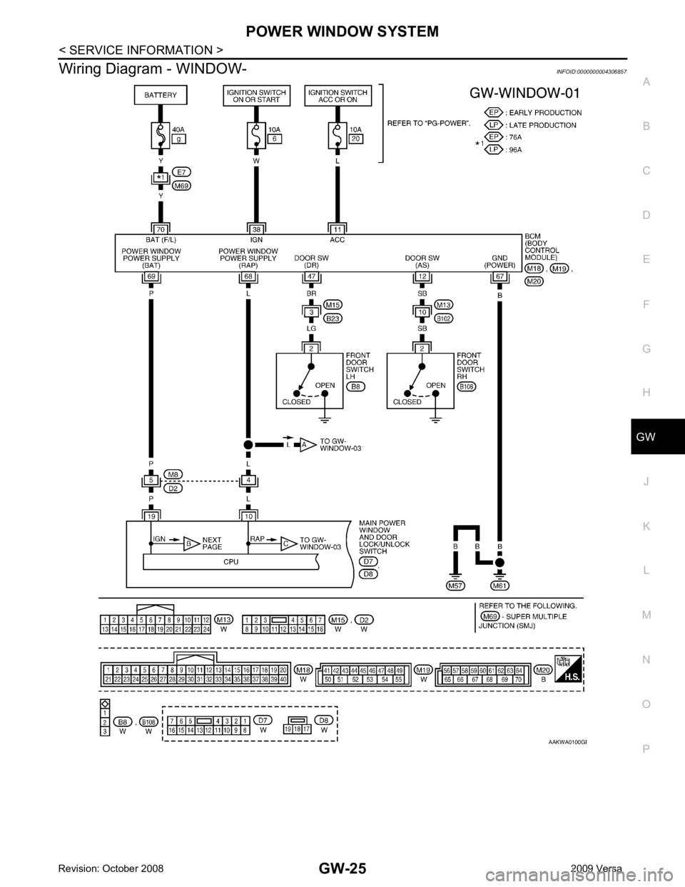
Wiring Diagram - WINDOW-
INFOID:0000000004306857 B