2009 NISSAN LATIO weight
[x] Cancel search: weightPage 3040 of 4331
EM
NP
O
DISASSEMBLY AND ASSEMBLY
ENGINE STAND SETTING
Setting INFOID:0000000004784310
NOTE:
Explained here is how to disassemble with engine stand supporting transmission surface. When using differ-
ent type of engine stand, note with difference in steps and etc.
1. Remove the engine and the transaxle assembly from the vehicle, and separate the transaxle from the
engine. Refer to EM-88, " Exploded View " .
2. Remove clutch cover and clutch disc (if equipped). Refer to CL-15, " Removal and Installation " .
3. Remove flywheel or driveplate. • Secure flywheel or driveplate with Tool, and remove bolts.
CAUTION:
• Never disassemble flywheel.
• Never place flywheel or driveplate with signal plate facing down.
• When handling signal plate, take car e not to damage or scratch it.
• Handle signal plate in a manner that prevents it from becoming magnetized.
4. Lift the engine with a hoist to install it onto widely use engine stand. CAUTION:
• Use the engine stand that has a load capacity [approximately 135 kg (298 lb) or more] large
enough for supporting the engine weight.
• If the load capacity of stand is not adequate, remove the following parts beforehand to reduce the poten-
tial risk of overturning stand.
- Intake manifold: Refer to EM-28, " Exploded View " .
- Exhaust manifold: Refer to EM-31, " Exploded View " .
- Rocker cover: Refer to EM-46, " Exploded View " .
NOTE:
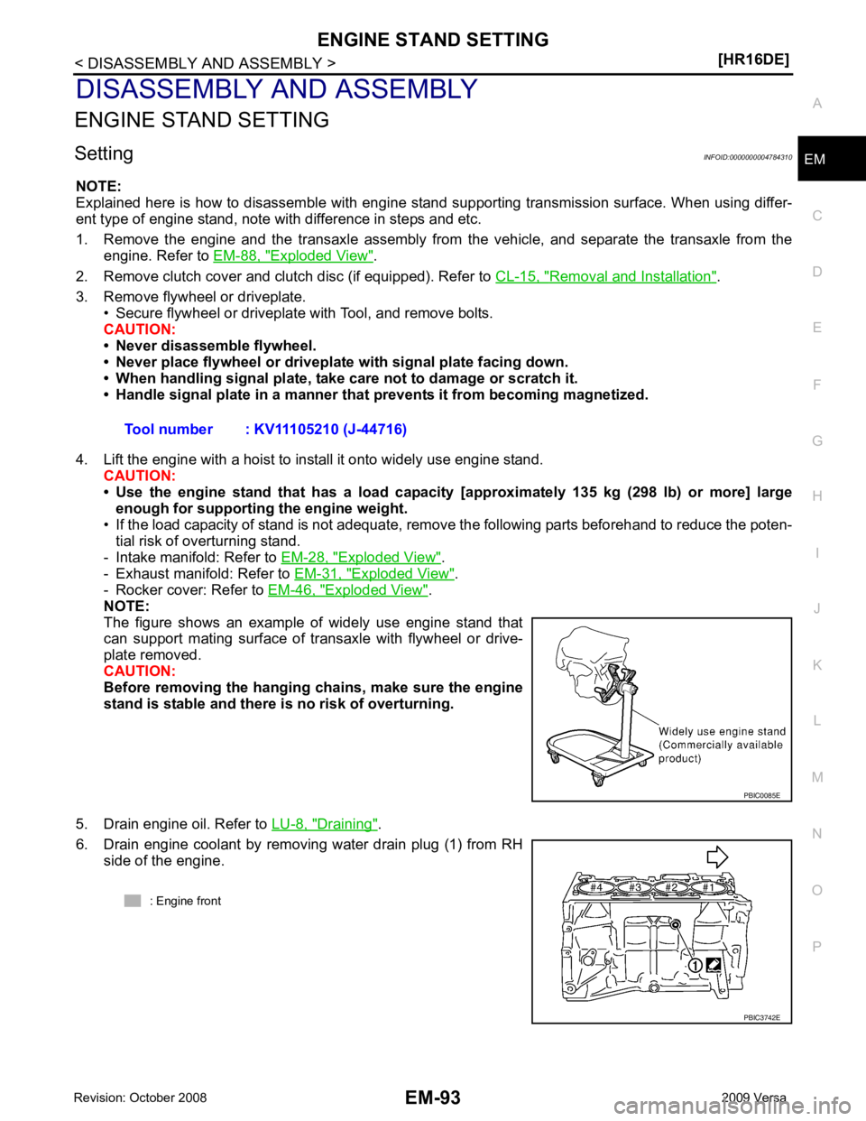
The figure shows an example of widely use engine stand that
can support mating surface of transaxle with flywheel or drive-
plate removed.
CAUTION:
Before removing the hanging chains, make sure the engine
stand is stable and there is no risk of overturning.
5. Drain engine oil. Refer to LU-8, " Draining " .
6. Drain engine coolant by removing water drain plug (1) from RH side of the engine. Tool number : KV11105210 (J-44716)
Page 3046 of 4331
EM
NP
O
CAUTION:
Dimension L1 of journal No. 3 is the distance fr om the housing base end surface (bulk) (not the
distance from the thrust bearing mounting end surface).
4. Install signal plate to crankshaft if removed.
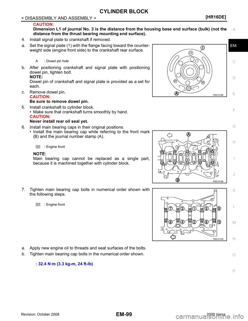
a. Set the signal plate (1) with the flange facing toward the counter- weight side (engine front side) to the crankshaft rear surface.
b. After positioning crankshaft and signal plate with positioning dowel pin, tighten bolt.
NOTE:
Dowel pin of crankshaft and signal plate is provided as a set for
each.
c. Remove dowel pin. CAUTION:
Be sure to remove dowel pin.
5. Install crankshaft to cylinder block. • Make sure that crankshaft turns smoothly by hand.
CAUTION:
Never install rear oil seal yet.
6. Install main bearing caps in their original positions. • Install the main bearing cap while referring to the front mark(B) and the journal number stamp (A).
NOTE:
Main bearing cap cannot be replaced as a single part,
because it is machined together with cylinder block.
7. Tighten main bearing cap bolts in numerical order shown with the following steps.
a. Apply new engine oil to threads and seat surfaces of the bolts.
b. Tighten main bearing cap bolts in the numerical order shown. A : Dowel pin hole
: Engine front PBIC3749E
Page 3147 of 4331

.
2. Install engine to engine stand as follows;
a. Remove flywheel (M/T models) or drive plate (1) (A/T or CVT models).
• Secure flywheel (M/T models) or drive plate (A/T or CVT mod-
els) using Tool (A), and remove bolts.
CAUTION:
Be careful not to damage or scratch drive plate (A/T or CVT
models) and contact surface for clutch disc of flywheel (M/T
models).
NOTE:
Figure shows drive plate (1) (A/T or CVT models)
b. Lift the engine with a hoist to install it onto widely use engine stand. CAUTION:
• Use the engine stand that has a load capacity [approximately 135 kg (298 lb) or more] large
enough for supporting the engine weight.
• If the load capacity of stand is not adequate, remo ve the following parts beforehand to reduce the poten-
tial risk of overturning stand.
- Exhaust manifold; Refer to EM-144 .
- Rocker cover; Refer to EM-153 .
NOTE:
The figure shows an example of widely used engine stand (A)
that can support mating surface of transaxle with flywheel (M/T
models) or drive plate (A/T or CVT models) removed.
CAUTION:
Before removing the hanging chains, make sure the engine
stand is stable and there is no risk of overturning.
3. Remove oil pan (upper and lower). Refer to EM-147 .
4. Remove cylinder head. Refer to EM-185 .
5. Remove thermostat housing. Refer to CO-45 .
6. Remove knock sensor. CAUTION:
Carefully handle knock sensor avoiding shocks.
7. Remove crankshaft position sensor (POS) cover and crankshaft position sensor (POS).
7. Oil pressure switch 8. Top ring 9. Second ring
10. Oil ring 11. Snap ring 12. Piston
13. Piston pin 14. Connecting rod 15. Thrust bearing
16. Connecting rod bearing upper 17. Main bearing upper 18. Crankshaft key
19. Main bearing lower 20. Connecting rod bearing lower 21. Connecting rod bearing cap
22. Connecting rod bolt 23. Main bearing cap 24. Main bearing cap bolt
25. Crankshaft 26. Pilot converter (A/T or CVT models) 27. Signal plate
28. Rear oil seal 29. Drive plate (A/T or CVT models) 30. Reinforcement plate (A/T or CVT models)
31. Flywheel (M/T models) 32. Block heater (Canada only) A. Refer to EM-200 PBIC3227J
Page 3256 of 4331
GI
N
O P
2. Use the Intelligent Key or mechanical key to turn the ignition switch to the
″ACC ″ position. At this time, the
steering lock will be released.
3. Disconnect both battery cables. The steering lock will remain released and the steering wheel can be
rotated.
4. Perform the necessary repair operation.
5. When the repair work is completed, return the ignition switch to the ″LOCK ″ position before connecting
the battery cables. (At this time, the steering lock mechanism will engage.)
6. Perform a self-diagnosis check of al l control units using CONSULT-III.
General Precaution INFOID:0000000004307347
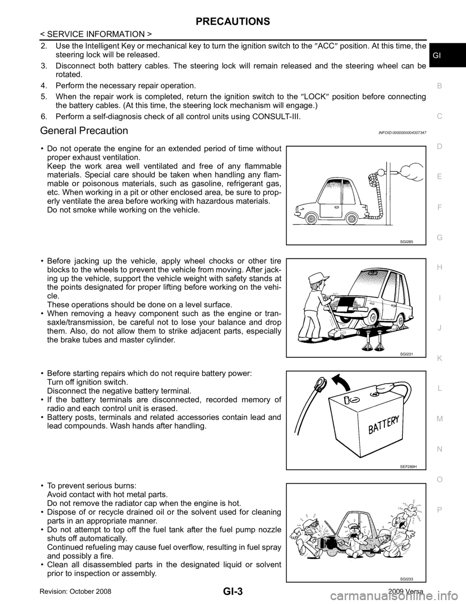
• Do not operate the engine for an extended period of time without proper exhaust ventilation.
Keep the work area well ventilated and free of any flammable
materials. Special care should be taken when handling any flam-
mable or poisonous materials, such as gasoline, refrigerant gas,
etc. When working in a pit or ot her enclosed area, be sure to prop-
erly ventilate the area before working with hazardous materials.
Do not smoke while working on the vehicle.
• Before jacking up the vehicle, apply wheel chocks or other tire blocks to the wheels to prevent t he vehicle from moving. After jack-
ing up the vehicle, support the vehicle weight with safety stands at
the points designated for proper lifting before working on the vehi-
cle.
These operations should be done on a level surface.
• When removing a heavy component such as the engine or tran-
saxle/transmission, be careful not to lose your balance and drop
them. Also, do not allow them to strike adjacent parts, especially
the brake tubes and master cylinder.
• Before starting repairs which do not require battery power: Turn off ignition switch.
Disconnect the negative battery terminal.
• If the battery terminals are disconnected, recorded memory of
radio and each control unit is erased.
• Battery posts, terminals and related accessories contain lead and lead compounds. Wash hands after handling.
• To prevent serious burns: Avoid contact with hot metal parts.
Do not remove the radiator cap when the engine is hot.
• Dispose of or recycle drained oil or the solvent used for cleaning
parts in an appropriate manner.
• Do not attempt to top off the fuel tank after the fuel pump nozzle shuts off automatically.
Continued refueling may cause fuel overflow, resulting in fuel spray
and possibly a fire.
• Clean all disassembled parts in the designated liquid or solvent
prior to inspection or assembly. SGI231
SGI233
Page 3271 of 4331
GI-18< SERVICE INFORMATION >
HOW TO USE THIS MANUAL
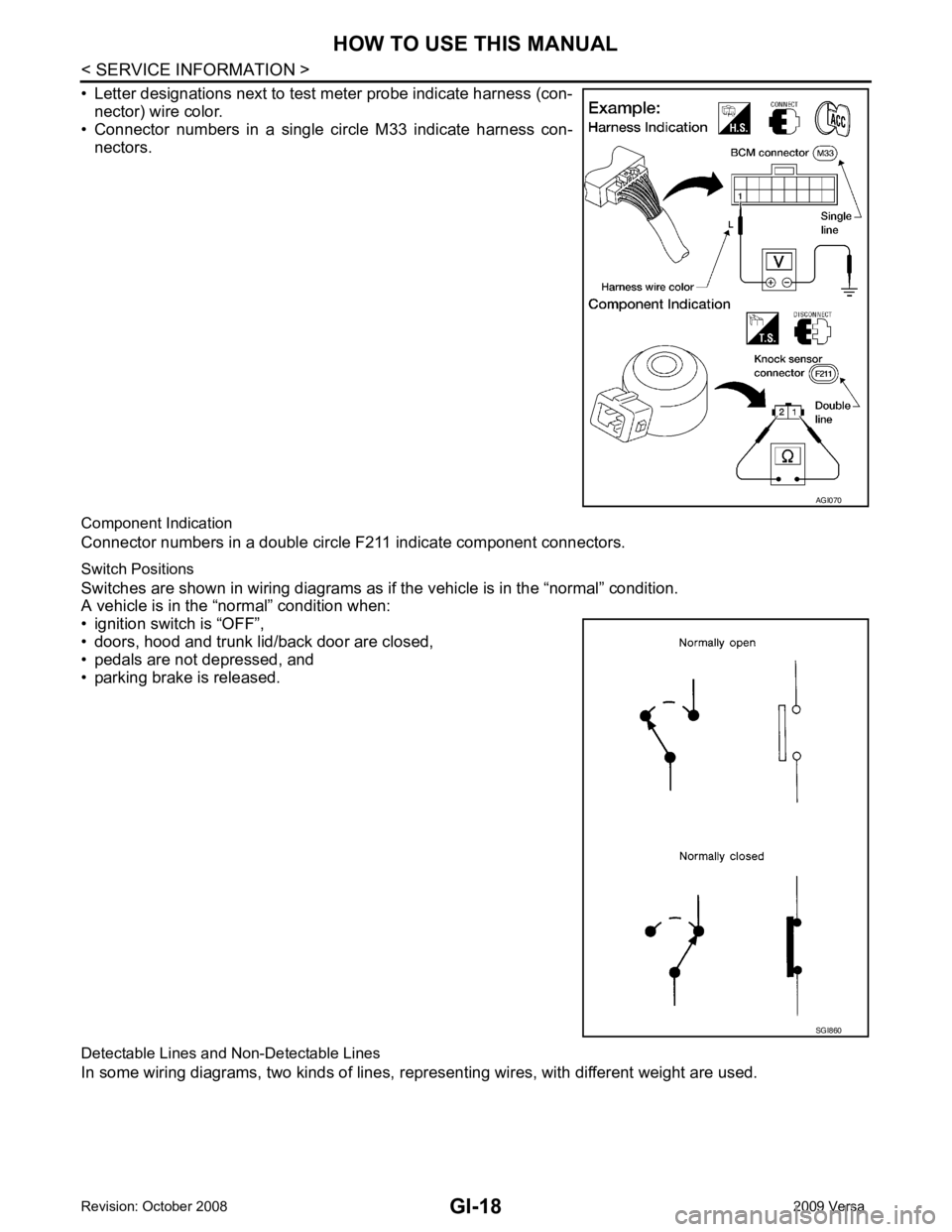
• Letter designations next to test meter probe indicate harness (con- nector) wire color.
• Connector numbers in a single circle M33 indicate harness con-
nectors.
Component Indication
Connector numbers in a double circle F211 indicate component connectors.
Switch Positions
Switches are shown in wiring diagrams as if the vehicle is in the “normal” condition.
A vehicle is in the “normal” condition when:
• ignition switch is “OFF”,
• doors, hood and trunk lid/back door are closed,
• pedals are not depressed, and
• parking brake is released.
Detectable Lines and Non-Detectable Lines
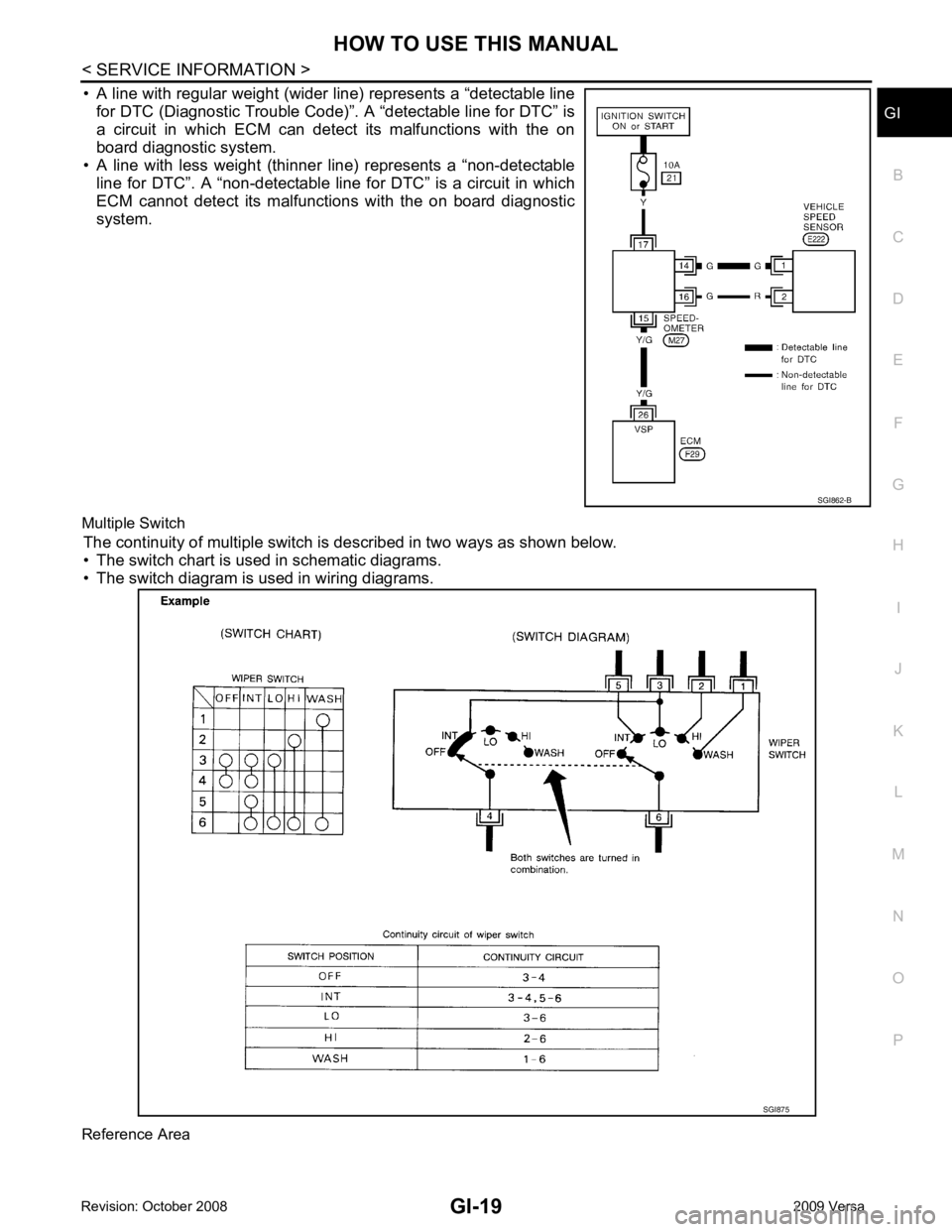
In some wiring diagrams, two kinds of lines, r epresenting wires, with different weight are used. AGI070
SGI860
Page 3272 of 4331
GI
N
O P
• A line with regular weight (wider line) represents a “detectable line
for DTC (Diagnostic Trouble Code)”. A “detectable line for DTC” is
a circuit in which ECM can detect its malfunctions with the on
board diagnostic system.
• A line with less weight (thinner line) represents a “non-detectable line for DTC”. A “non-detectable line for DTC” is a circuit in which
ECM cannot detect its malfunctions with the on board diagnostic
system.
Multiple Switch The continuity of multiple switch is described in two ways as shown below.
• The switch chart is used in schematic diagrams.
• The switch diagram is used in wiring diagrams.
Reference Area SGI875
Page 3627 of 4331
LT
N
O P
Aiming Adjustment
INFOID:0000000004306537
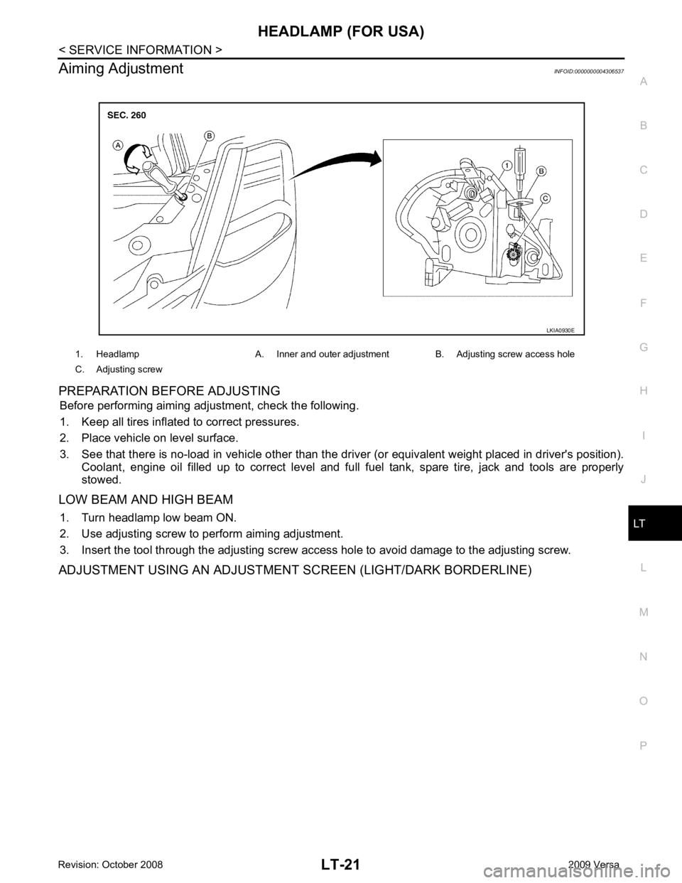
PREPARATION BEFORE ADJUSTING Before performing aiming adjustment, check the following.
1. Keep all tires inflated to correct pressures.
2. Place vehicle on level surface.
3. See that there is no-load in vehicle other than the driv er (or equivalent weight placed in driver's position).
Coolant, engine oil filled up to correct level and full fuel tank, spare tire, jack and tools are properly
stowed.
LOW BEAM AND HIGH BEAM 1. Turn headlamp low beam ON.
2. Use adjusting screw to perform aiming adjustment.
3. Insert the tool through the adjusting screw acce ss hole to avoid damage to the adjusting screw.
ADJUSTMENT USING AN ADJUSTMENT SCREEN (LIGHT/DARK BORDERLINE) 1. Headlamp A. Inner and outer adjustment B. Adjusting screw access hole
C. Adjusting screw
Page 3641 of 4331
HEADLAMP (FOR CANADA) - DA
YTIME LIGHT SYSTEM -
LT-35
< SERVICE INFORMATION >
C
D E
F
G H
I
J
L
M A
B LT
N
O P
Aiming Adjustment
INFOID:0000000004306553
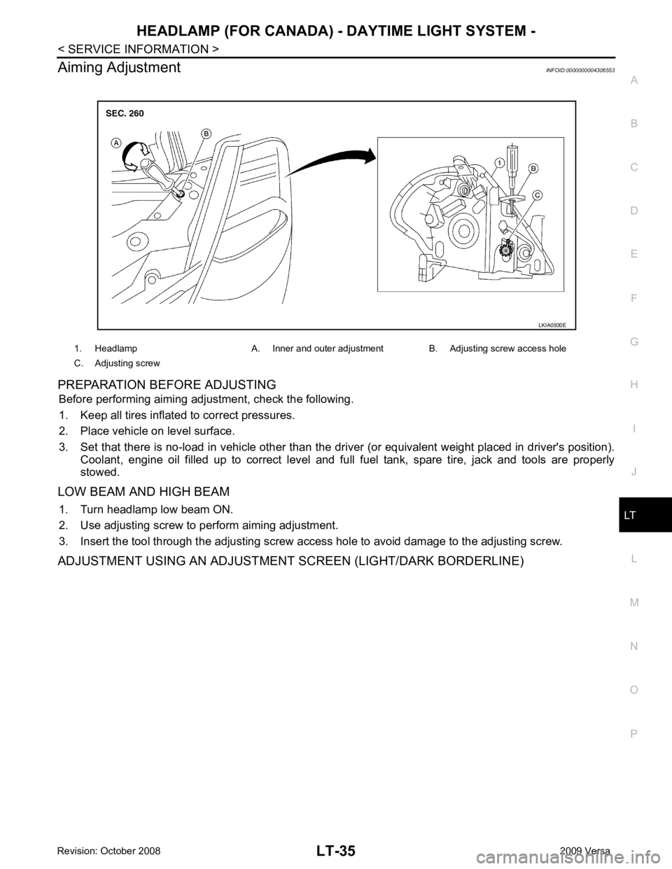
PREPARATION BEFORE ADJUSTING Before performing aiming adjustment, check the following.
1. Keep all tires inflated to correct pressures.
2. Place vehicle on level surface.
3. Set that there is no-load in vehicle other than the driv er (or equivalent weight placed in driver's position).
Coolant, engine oil filled up to correct level and full fuel tank, spare tire, jack and tools are properly
stowed.
LOW BEAM AND HIGH BEAM 1. Turn headlamp low beam ON.
2. Use adjusting screw to perform aiming adjustment.
3. Insert the tool through the adjusting screw a ccess hole to avoid damage to the adjusting screw.
ADJUSTMENT USING AN ADJUSTMENT SCREEN (LIGHT/DARK BORDERLINE) 1. Headlamp A. Inner and outer adjustment B. Adjusting screw access hole
C. Adjusting screw LKIA0930E