Page 369 of 4331
" Component " .
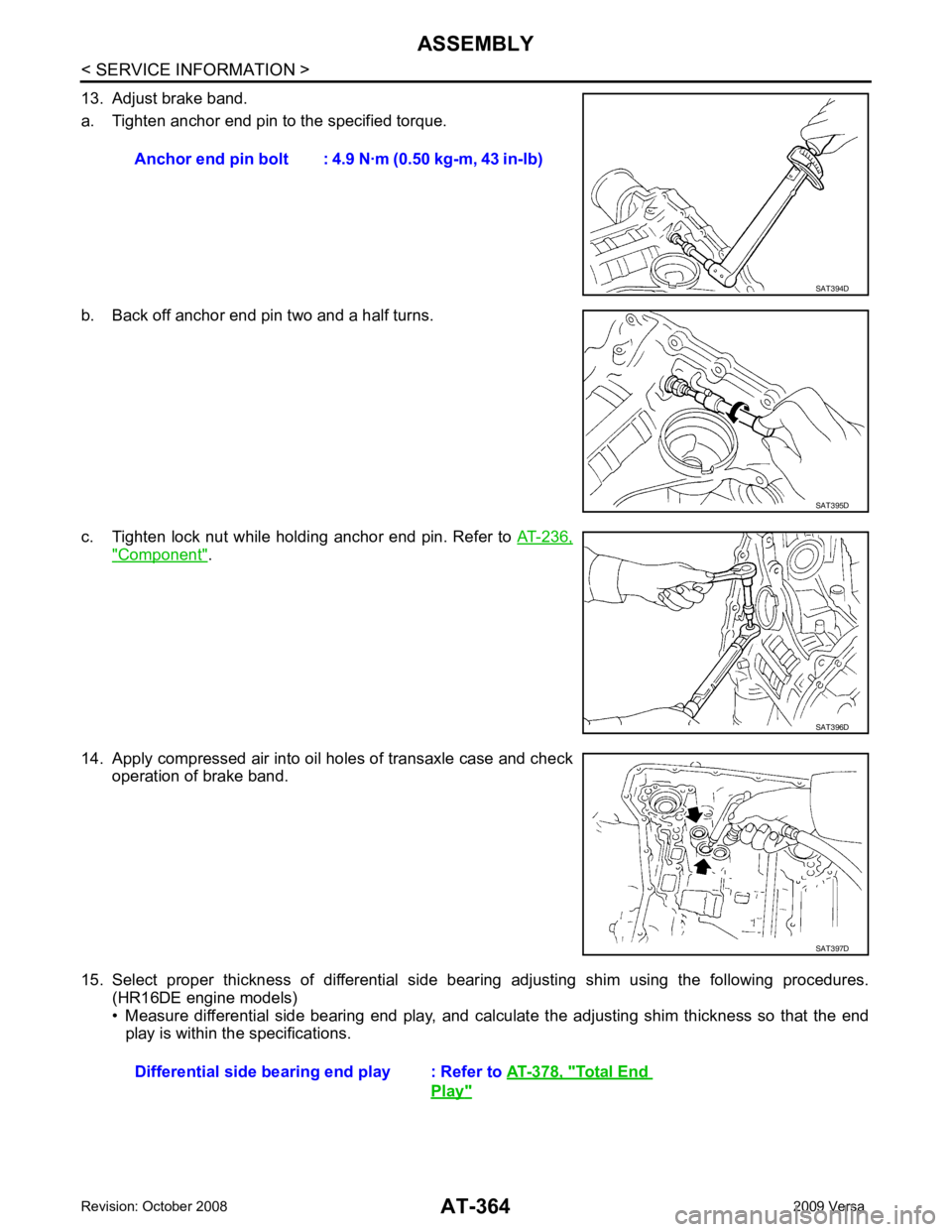
14. Apply compressed air into oil holes of transaxle case and check operation of brake band.
15. Select proper thickness of differential side bear ing adjusting shim using the following procedures.
(HR16DE engine models)
• Measure differential side bearing end play, and calculat e the adjusting shim thickness so that the end
play is within the specifications. Anchor end pin bolt : 4.9
N·m (0.50 kg-m, 43 in-lb) SAT395D
SAT396D
Total End
Play "
Page 803 of 4331
BR
N
O P
5. When the repair work is completed, return the ignition switch to the
″LOCK ″ position before connecting
the battery cables. (At this time, the steering lock mechanism will engage.)
6. Perform a self-diagnosis check of al l control units using CONSULT-III.
Precaution for Brake System INFOID:0000000004305887
• Refill using recommended brake fluid. Refer to MA-14 .
• Never reuse drained brake fluid.
• Be careful not to splash brake fluid on painted surfac e of body. If brake fluid is splashed on painted surfaces
of body immediately wipe it off with cloth and then wash it away with water.
• To clean or wash all parts of master cylinder, disc brake caliper and wheel cylinder, use new brake fluid.
• Never use mineral oils such as gasoline or kerosene. They will ruin rubber parts of the hydraulic system.
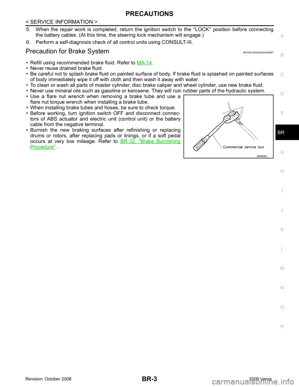
• Use a flare nut wrench when removing a brake tube and use a flare nut torque wrench when installing a brake tube.
• When installing brake tubes and hoses, be sure to check torque.
• Before working, turn igniti on switch OFF and disconnect connec-
tors of ABS actuator and electric unit (control unit) or the battery
cable from the negative terminal.
• Burnish the new braking surfaces after refinishing or replacing drums or rotors, after replacing p ads or linings, or if a soft pedal
occurs at very low mileage. Refer to BR-32, " Brake Burnishing
Procedure " .
Page 823 of 4331
BR
N
O P
VACUUM LINES
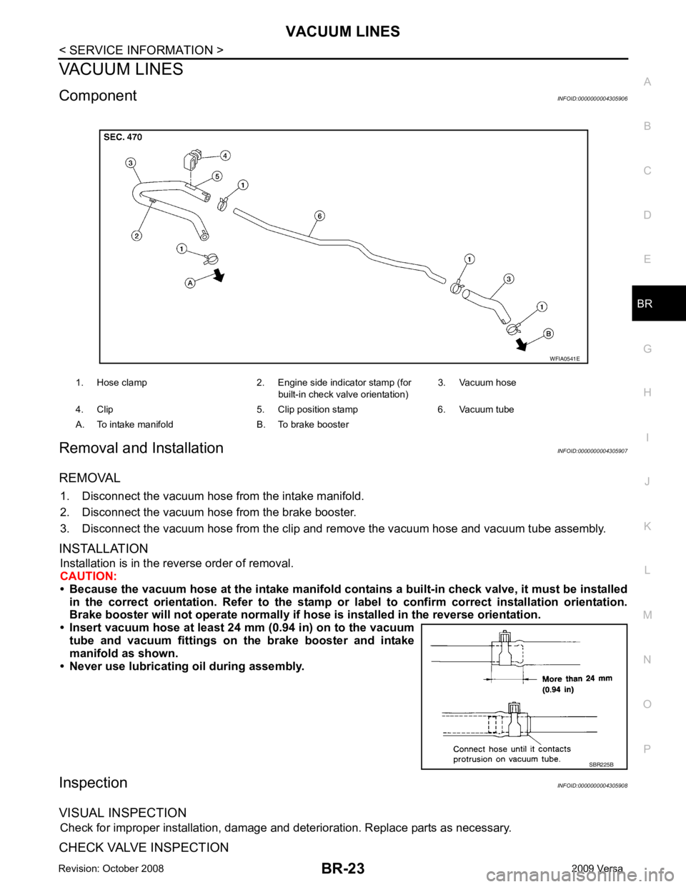
Component INFOID:0000000004305906
Removal and Installation INFOID:0000000004305907
REMOVAL 1. Disconnect the vacuum hose from the intake manifold.
2. Disconnect the vacuum hose from the brake booster.
3. Disconnect the vacuum hose from the clip and re move the vacuum hose and vacuum tube assembly.
INSTALLATION Installation is in the reverse order of removal.
CAUTION:
• Because the vacuum hose at the intake manifold contai ns a built-in check valve, it must be installed
in the correct orientation. Refer to the stamp or label to confirm correct installation orientation.
Brake booster will not operate normally if ho se is installed in the reverse orientation.
• Insert vacuum hose at least 24 mm (0.94 in) on to the vacuum tube and vacuum fittings on the brake booster and intake
manifold as shown.
• Never use lubricating oil during assembly.
Inspection INFOID:0000000004305908
VISUAL INSPECTION Check for improper installation, damage and deterioration. Replace parts as necessary.
CHECK VALVE INSPECTION 1. Hose clamp 2. Engine side indicator stamp (for
built-in check valve orientation)3. Vacuum hose
4. Clip 5. Clip position stamp 6. Vacuum tube
A. To intake manifold B. To brake booster SBR225B
Page 829 of 4331
BR
N
O P
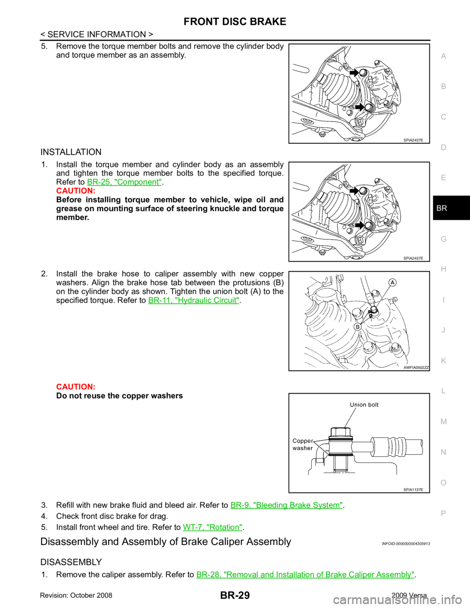
5. Remove the torque member bolts and remove the cylinder body
and torque member as an assembly.
INSTALLATION 1. Install the torque member and cylinder body as an assembly and tighten the torque member bolts to the specified torque.
Refer to BR-25, " Component " .
CAUTION:
Before installing torque member to vehicle, wipe oil and
grease on mounting surface of steering knuckle and torque
member.
2. Install the brake hose to caliper assembly with new copper washers. Align the brake hose tab between the protusions (B)
on the cylinder body as shown. Tighten the union bolt (A) to the
specified torque. Refer to BR-11, " Hydraulic Circuit " .
CAUTION:
Do not reuse the copper washers
3. Refill with new brake fluid and bleed air. Refer to BR-9, " Bleeding Brake System " .
4. Check front disc brake for drag.
5. Install front wheel and tire. Refer to WT-7, " Rotation " .
Disassembly and Assembly of Brake Caliper Assembly INFOID:0000000004305913
DISASSEMBLY 1. Remove the caliper assembly. Refer to BR-28, " Removal and Installation of Brake Caliper Assembly " .AWFIA0502ZZ
SFIA1137E
Page 830 of 4331
BR-30< SERVICE INFORMATION >
FRONT DISC BRAKE
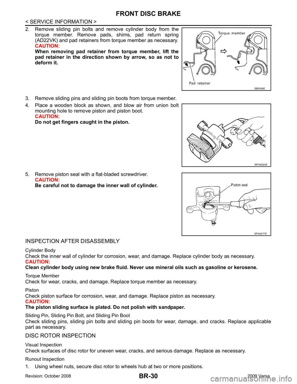
2. Remove sliding pin bolts and remove cylinder body from the torque member. Remove pads, shims, pad return spring
(AD22VK) and pad retainers from torque member as necessary.
CAUTION:
When removing pad retainer fr om torque member, lift the
pad retainer in the direction shown by arrow, so as not to
deform it.
3. Remove sliding pins and sliding pin boots from torque member.
4. Place a wooden block as shown, and blow air from union bolt mounting hole to remove piston and piston boot.
CAUTION:
Do not get fingers caught in the piston.
5. Remove piston seal with a flat-bladed screwdriver. CAUTION:
Be careful not to damage the inner wall of cylinder.
INSPECTION AFTER DISASSEMBLY
Cylinder Body
Check the inner wall of cylinder for corrosion, w ear, and damage. Replace cylinder body as necessary.
CAUTION:
Clean cylinder body using new brake fluid. Never use mineral oils such as gasoline or kerosene.
Torque Member
Check for wear, cracks, and damage. R eplace torque member as necessary.
Piston
Check piston surface for corrosion, wear, and damage. Replace piston as necessary.
CAUTION:
The piston sliding surface is plated . Do not polish with sandpaper.
Sliding Pin, Sliding Pin Bolt, and Sliding Pin Boot
Check sliding pins, sliding pin bolts and sliding pin boots for wear, damage, and cracks. Replace applicable
part as necessary.
DISC ROTOR INSPECTION
Visual Inspection
Check surfaces of disc rotor for uneven wear, cr acks, and serious damage. Replace as necessary.
Runout Inspection
1. Using wheel nuts, secure disc rotor to wheels hub at two or more positions. SBR556E
WFIA0525E
SFIA2277E
Page 891 of 4331
CL
N
O P
CLUTCH DISC, CLUTCH COVER AND FLYWHEEL
Removal and Installation INFOID:0000000004305174
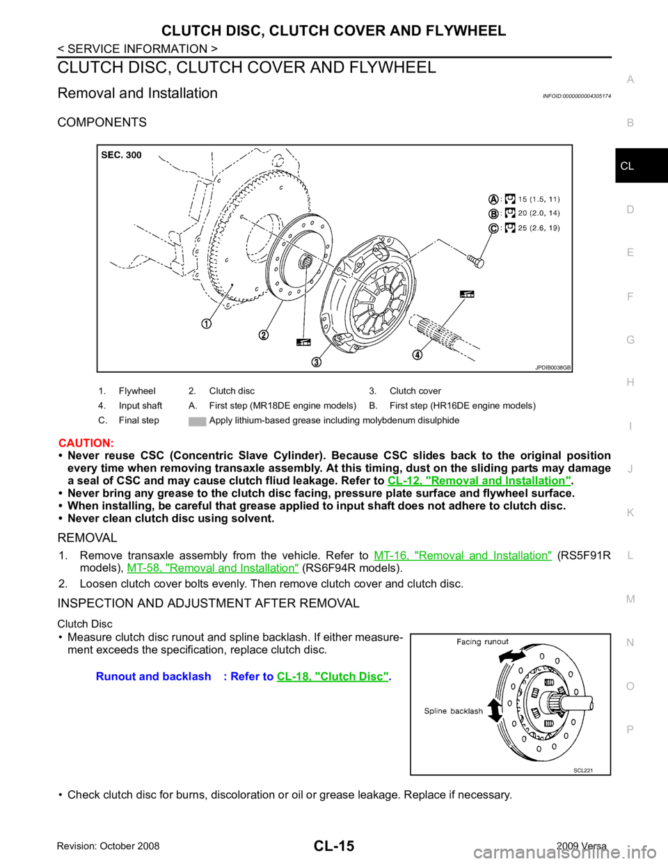
COMPONENTS
CAUTION:
• Never reuse CSC (Concentric Slave Cylinder). B ecause CSC slides back to the original position
every time when removing transaxle assembly. At th is timing, dust on the sliding parts may damage
a seal of CSC and may cause clut ch fliud leakage. Refer to CL-12, " Removal and Installation " .
• Never bring any grease to the clutch disc faci ng, pressure plate surface and flywheel surface.
• When installing, be careful that grease applied to input shaft does not adhere to clutch disc.
• Never clean clutch disc using solvent.
REMOVAL 1. Remove transaxle assembly from the vehicle. Refer to MT-16, " Removal and Installation " (RS5F91R
models), MT-58, " Removal and Installation " (RS6F94R models).
2. Loosen clutch cover bolts evenly. Then remove clutch cover and clutch disc.
INSPECTION AND ADJUSTMENT AFTER REMOVAL
Clutch Disc • Measure clutch disc runout and spline backlash. If either measure- ment exceeds the specificat ion, replace clutch disc.
• Check clutch disc for burns, discoloration or oil or grease leakage. Replace if necessary.
1. Flywheel 2. Clutch disc 3. Clutch cover
4. Input shaft A. First step (MR18DE engine models) B. First step (HR16DE engine models)
C. Final step Apply lithium-based grease including molybdenum disulphide Clutch Disc " .
Page 917 of 4331
CO
NP
O
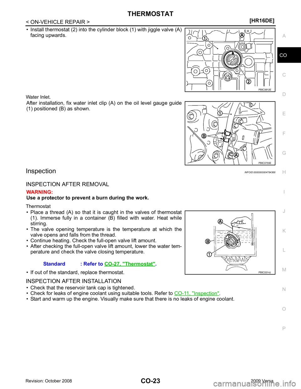
• Install thermostat (2) into the cylinder block (1) with jiggle valve (A)
facing upwards.
Water Inlet. After installation, fix water inlet clip (A) on the oil level gauge guide
(1) positioned (B) as shown.
Inspection INFOID:0000000004784366
INSPECTION AFTER REMOVAL WARNING:
Use a protector to prevent a burn during the work.
Thermostat • Place a thread (A) so that it is caught in the valves of thermostat (1). Immerse fully in a container (B) filled with water. Heat while
stirring.
• The valve opening temperature is the temperature at which the valve opens and falls from the thread.
• Continue heating. Check the full-open valve lift amount.
• After checking the full-open valve lift amount, lower the water tem- perature and check the valve closing temperature.
• If out of the standard, replace thermostat.
INSPECTION AFTER INSTALLATION • Check that the reservoir tank cap is tightened.
• Check for leaks of engine coolant using suitable tools. Refer to CO-11, " Inspection " .
• Start and warm up the engine. Visually make sure that there is no leaks of engine coolant. PBIC3755E
Thermostat " .
Page 934 of 4331
![NISSAN LATIO 2009 Service Repair Manual CO-40< SERVICE INFORMATION >
[MR18DE]
RADIATOR
Checking Radiator Cap INFOID:0000000004305238
• Check valve seat of radiator cap.
- Check if valve seat is swollen to the extent that the e](/manual-img/5/57359/w960_57359-933.png "NISSAN LATIO 2009 Service Repair Manual CO-40< SERVICE INFORMATION >
[MR18DE]
RADIATOR
Checking Radiator Cap INFOID:0000000004305238
• Check valve seat of radiator cap.
- Check if valve seat is swollen to the extent that the e")
CO-40< SERVICE INFORMATION >
[MR18DE]
RADIATOR
Checking Radiator Cap INFOID:0000000004305238
• Check valve seat of radiator cap.
- Check if valve seat is swollen to the extent that the edge of the plunger cannot be seen when watching it vertically from the top.
- Check if valve seat has no soil and damage.
• Pull negative-pressure valve to open it, and make sure that it is completely closed when released.
- Make sure that there is no dirt or damage on the valve seat of radi-
ator cap negative-pressure valve.
- Make sure that the valve operates properly in the opening and closing conditions.
• Check radiator cap relief pressure using Tool.
- When connecting the radiator cap to the tester, apply water or coolant to the cap seal surface.
- Replace the radiator cap if ther e is an abnormality in the negative-
pressure valve, or if the open-valve pr essure is outside of the standard values.
• Replace radiator cap if there it does not comply to specifications to the above three checks.
CAUTION:
When installing radiator cap, thoroughly wipe out the radiator filler neck to remove any waxy residue
or foreign material.
Checking Radiator INFOID:0000000004305239
Check radiator for mud or clogging. If necessary, clean radiator as follows.
• Be careful not to bend or damage radiator fins.
• When radiator is cleaned without removal, remove all surrounding parts such as cooling fan, radiator shroud and horns. Then tape harness and connectors to prevent water from entering.
1. Apply water by hose to the back side of the radiator core vertically downward.
2. Apply water again to all radiator core surface once per minute.
3. Stop washing if any stains no longer flow out from radiator.
4. Blow air into the back side of radiator core vertically downward. • Use compressed air lower than 490 kPa (4.9 bar, 5 kg/cm 2
, 71 psi) and keep distance more than 30 cm
(11.8 in).
5. Blow air again into all the radiator core surfaces once per minute until no water sprays out. PBIC2816E
SMA967B
Tool number : EG17650301 (J-33984-A)
Standard: 78 – 98 kPa (0.78 - 0.98 bar, 0.8 – 1.0 kg/cm 2
, 11
– 14 psi)
Limit: 59 kPa (0.59 bar, 0.6 kg/cm 2
, 9 psi) WBIA0570E