Page 3780 of 4331
MA
N
O P
CHASSIS AND BODY MAINTENANCE
IN-CABIN MICROFILTER
IN-CABIN MICROFILTER : Removal and Installation INFOID:0000000004683699
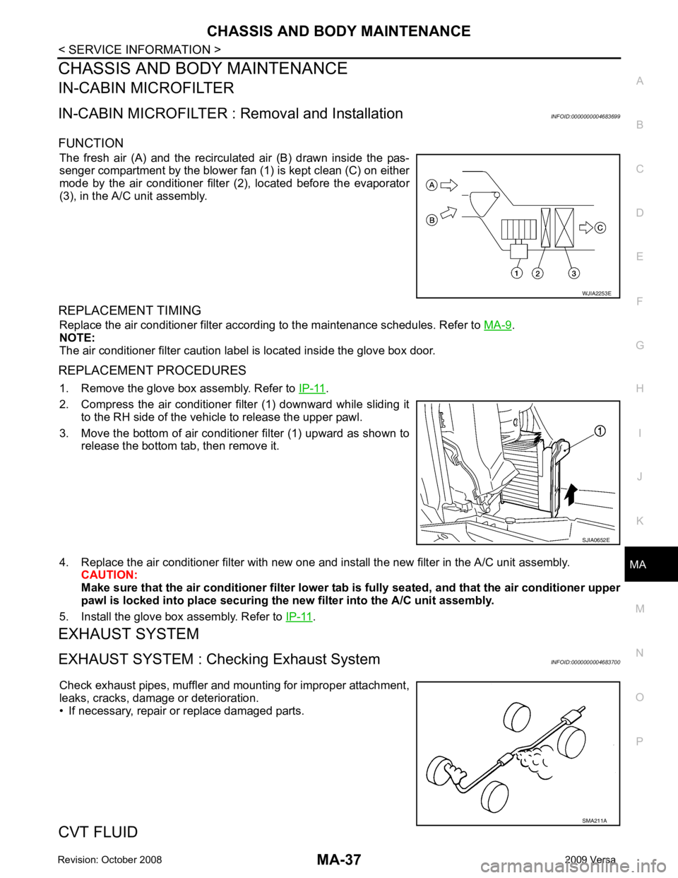
FUNCTION The fresh air (A) and the recirculated air (B) drawn inside the pas-
senger compartment by the blower fan (1) is kept clean (C) on either
mode by the air conditioner filter (2), located before the evaporator
(3), in the A/C unit assembly.
REPLACEMENT TIMING Replace the air conditioner filter according to the maintenance schedules. Refer to MA-9 .
NOTE:
The air conditioner filter caution label is located inside the glove box door.
REPLACEMENT PROCEDURES 1. Remove the glove box assembly. Refer to IP-11 .
2. Compress the air conditioner filter (1) downward while sliding it to the RH side of the vehicle to release the upper pawl.
3. Move the bottom of air conditioner filter (1) upward as shown to
release the bottom tab, then remove it.
4. Replace the air conditioner filter with new one and in stall the new filter in the A/C unit assembly.
CAUTION:
Make sure that the air cond itioner filter lower tab is fully seated , and that the air conditioner upper
pawl is locked into place securing the new filter into the A/C unit assembly.
5. Install the glove box assembly. Refer to IP-11 .
EXHAUST SYSTEM
EXHAUST SYSTEM : Chec king Exhaust System INFOID:0000000004683700
Check exhaust pipes, muffler and mounting for improper attachment,
leaks, cracks, damage or deterioration.
• If necessary, repair or replace damaged parts.
CVT FLUID SMA211A
Page 3781 of 4331
MA-38< SERVICE INFORMATION >
CHASSIS AND BODY MAINTENANCE
CVT FLUID : Checking CVT Fluid (RE0F08A) INFOID:0000000004803426
FLUID LEVEL CHECK
Fluid level should be checked with the fluid warmed up to 50 ° to 80 °C (122 ° to 176 °F).
1. Check for fluid leakage.
2. With the engine warmed up, drive the vehicle to warm up the CVT fluid. When ambient temperature is 20 °C (68 °F), it takes
about 10 minutes for the CVT fluid to warm up to 50 ° to 80 °C
(122 ° to 176 °F).
3. Park the vehicle on a level surface and set the parking brake.
4. With engine at idle, while depressing brake pedal, move the selector lever throughout the entire shift range and return it to
the “P” position.
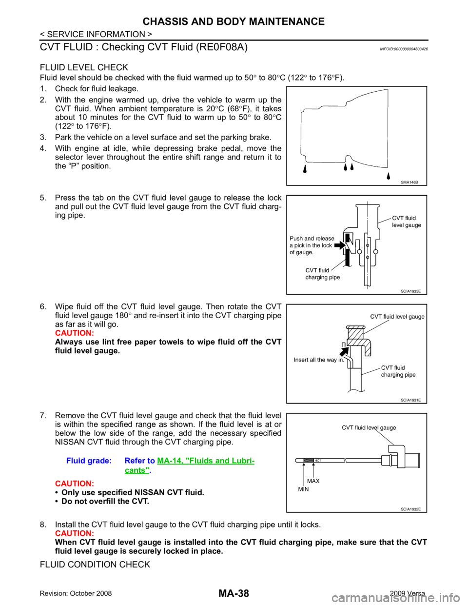
5. Press the tab on the CVT fluid level gauge to release the lock and pull out the CVT fluid level gauge from the CVT fluid charg-
ing pipe.
6. Wipe fluid off the CVT fluid level gauge. Then rotate the CVT fluid level gauge 180 ° and re-insert it into the CVT charging pipe
as far as it will go.
CAUTION:
Always use lint free paper towels to wipe fluid off the CVT
fluid level gauge.
7. Remove the CVT fluid level gauge and check that the fluid level is within the specified range as shown. If the fluid level is at or
below the low side of the range, add the necessary specified
NISSAN CVT fluid through the CVT charging pipe.
CAUTION:
• Only use specified NISSAN CVT fluid.
• Do not overfill the CVT.
8. Install the CVT fluid level gauge to the CVT fluid charging pipe until it locks. CAUTION:
When CVT fluid level gauge is in stalled into the CVT fluid charging pipe, make sure that the CVT
fluid level gauge is securely locked in place.
FLUID CONDITION CHECK SMA146B
SCIA1933E
SCIA1931E
Fluid grade: Refer to
MA-14, " Fluids and Lubri-
cants " .
SCIA1932E
Page 3783 of 4331
MA-40< SERVICE INFORMATION >
CHASSIS AND BODY MAINTENANCE
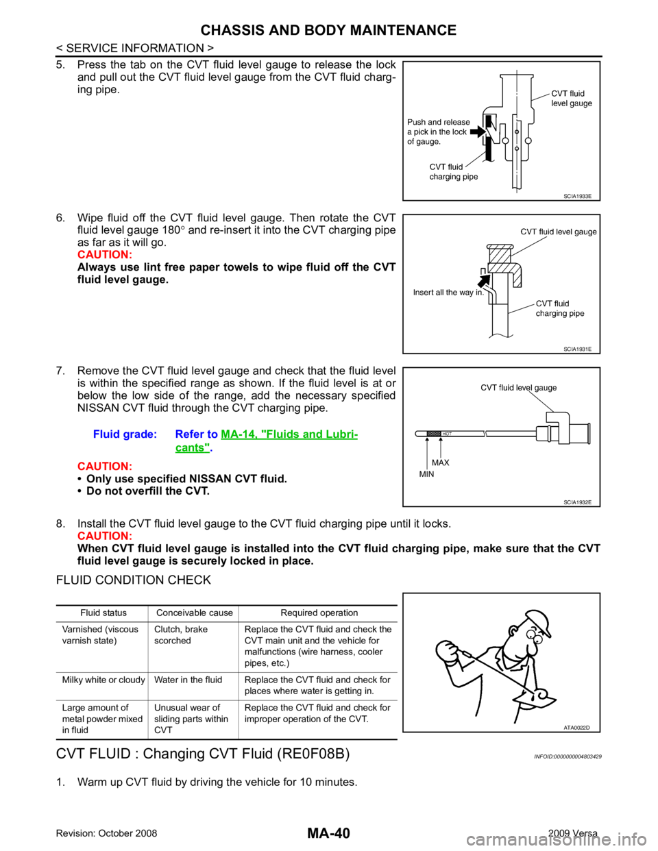
5. Press the tab on the CVT fluid level gauge to release the lock and pull out the CVT fluid level gauge from the CVT fluid charg-
ing pipe.
6. Wipe fluid off the CVT fluid level gauge. Then rotate the CVT fluid level gauge 180 ° and re-insert it into the CVT charging pipe
as far as it will go.
CAUTION:
Always use lint free paper towels to wipe fluid off the CVT
fluid level gauge.
7. Remove the CVT fluid level gauge and check that the fluid level is within the specified range as shown. If the fluid level is at or
below the low side of the range, add the necessary specified
NISSAN CVT fluid through the CVT charging pipe.
CAUTION:
• Only use specified NISSAN CVT fluid.
• Do not overfill the CVT.
8. Install the CVT fluid level gauge to the CVT fluid charging pipe until it locks. CAUTION:
When CVT fluid level gauge is in stalled into the CVT fluid charging pipe, make sure that the CVT
fluid level gauge is securely locked in place.
FLUID CONDITION CHECK
CVT FLUID : Changing CVT Fluid (RE0F08B) INFOID:0000000004803429
1. Warm up CVT fluid by driving the vehicle for 10 minutes. SCIA1933E
SCIA1931E
Fluid grade: Refer to
MA-14, " Fluids and Lubri-
cants " .
SCIA1932E
Fluid status Conceivable cause Required operation
Varnished (viscous
varnish state) Clutch, brake
scorched Replace the CVT fluid and check the
CVT main unit and the vehicle for
malfunctions (wire harness, cooler
pipes, etc.)
Milky white or cloudy Water in the fluid Replace the CVT fluid and check for places where water is getting in.
Large amount of
metal powder mixed
in fluid Unusual wear of
sliding parts within
CVT Replace the CVT fluid and check for
improper operation of the CVT. ATA0022D
Page 3809 of 4331
MT
N
O P
AIR BREATHER HOSE
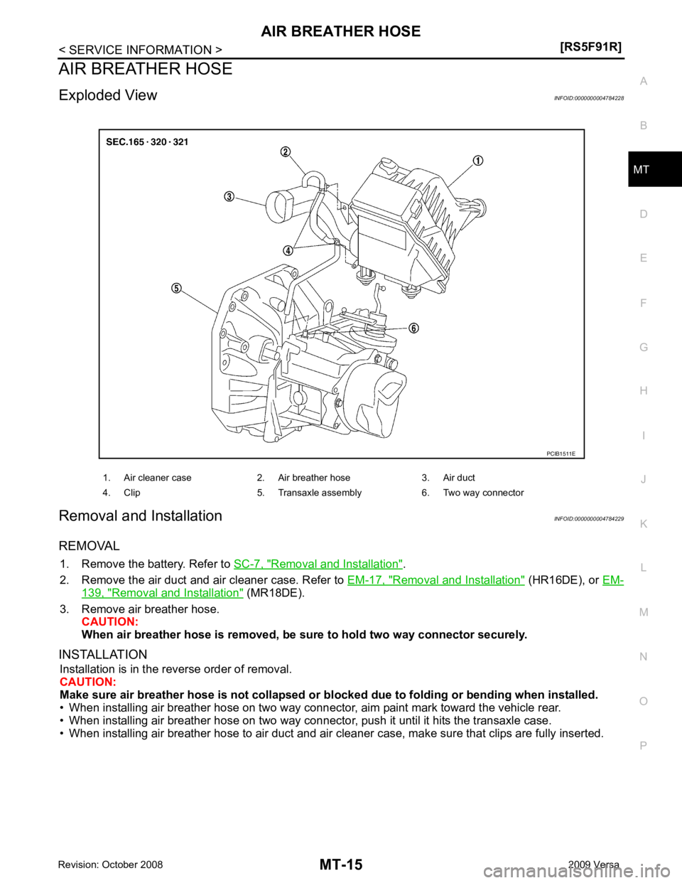
Exploded View INFOID:0000000004784228
Removal and Installation INFOID:0000000004784229
REMOVAL 1. Remove the battery. Refer to SC-7, " Removal and Installation " .
2. Remove the air duct and air cleaner case. Refer to EM-17, " Removal and Installation " (HR16DE), or
EM- 139, " Removal and Installation " (MR18DE).
3. Remove air breather hose. CAUTION:
When air breather hose is removed, be su re to hold two way connector securely.
INSTALLATION Installation is in the reverse order of removal.
CAUTION:
Make sure air breather hose is not collapsed or bl ocked due to folding or bending when installed.
• When installing air breather hose on two way connector, aim paint mark toward the vehicle rear.
• When installing air breather hose on two way connecto r, push it until it hits the transaxle case.
• When installing air breather hose to air duct and air cleaner case, make sure that clips are fully inserted. 1. Air cleaner case 2. Air breather hose 3. Air duct
4. Clip 5. Transaxle assembly 6. Two way connector
Page 3831 of 4331
MT
N
O P
MAINSHAFT AND GEAR
Disassembly and Assembly INFOID:0000000004788551
GENERAL PRECAUTIONS • Never reuse snap ring.
• Secure mainshaft in a vise with backplate, and then remove gears and snap rings.
• For installation and removal of snap ring, set snap ring pliers and flat pliers at both sides of snap ring. While expanding snap ring
with snap ring pliers, move snap ring with flat pliers.
• Disassemble gear components putting direction marks on the parts that never affect any functions.
DISASSEMBLY 1. Remove 3rd-4th synchronizer hub and 3rd baulk ring.
2. Remove snap ring (1) and thrust washer (2) using suitable tools.
3. Remove 3rd main gear (1) and thrust washer (2).
4. Remove snap ring (1) and thrust washer (2) using suitable tools.
Page 3833 of 4331
MT
N
O P
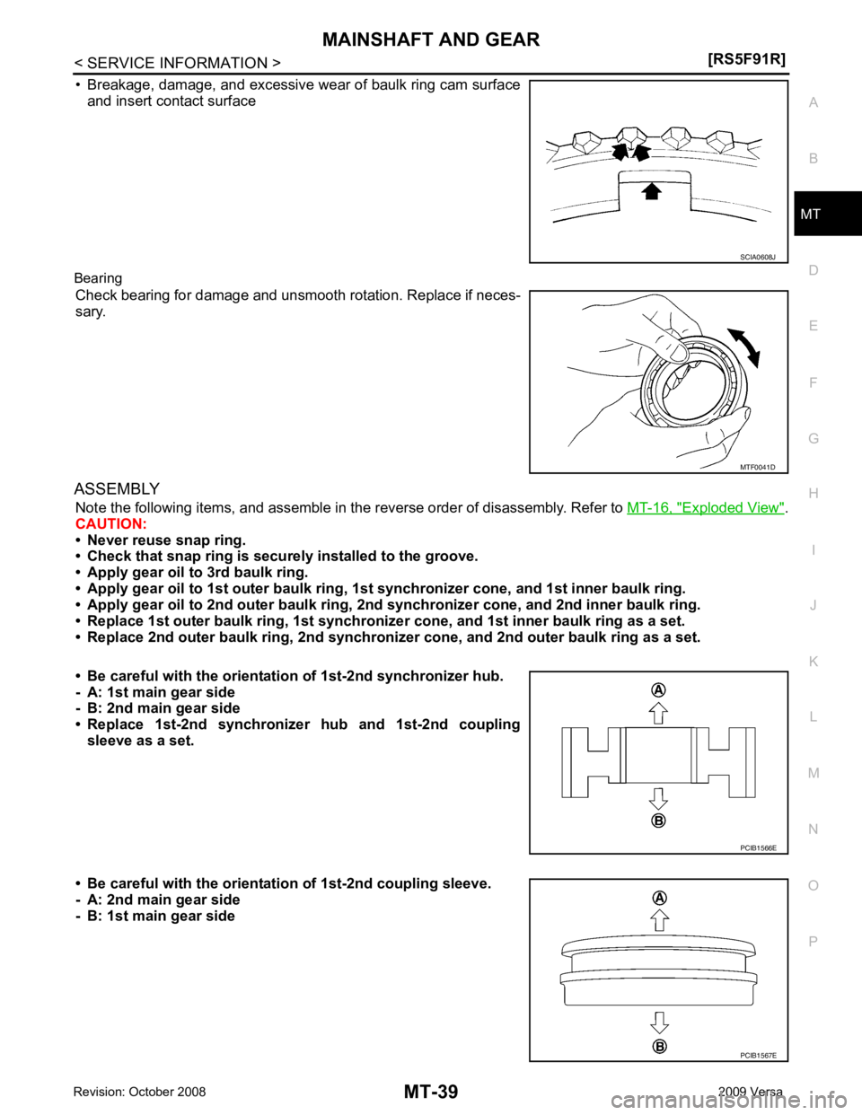
• Breakage, damage, and excessive wear of baulk ring cam surface
and insert contact surface
Bearing Check bearing for damage and unsmooth rotation. Replace if neces-
sary.
ASSEMBLY Note the following items, and assemble in t he reverse order of disassembly. Refer to MT-16, " Exploded View " .
CAUTION:
• Never reuse snap ring.
• Check that snap ring is secu rely installed to the groove.
• Apply gear oil to 3rd baulk ring.
• Apply gear oil to 1st outer baulk ring, 1st synchronizer cone, and 1st inner baulk ring.
• Apply gear oil to 2nd outer baulk ring, 2n d synchronizer cone, and 2nd inner baulk ring.
• Replace 1st outer baulk ring, 1st synchronize r cone, and 1st inner baulk ring as a set.
• Replace 2nd outer baulk ring, 2nd synchronize r cone, and 2nd outer baulk ring as a set.
• Be careful with the orientation of 1st-2nd synchronizer hub.
- A: 1st main gear side
- B: 2nd main gear side
• Replace 1st-2nd synchronize r hub and 1st-2nd coupling
sleeve as a set.
• Be careful with the orientation of 1st-2nd coupling sleeve.
- A: 2nd main gear side
- B: 1st main gear side MTF0041D
Page 3850 of 4331
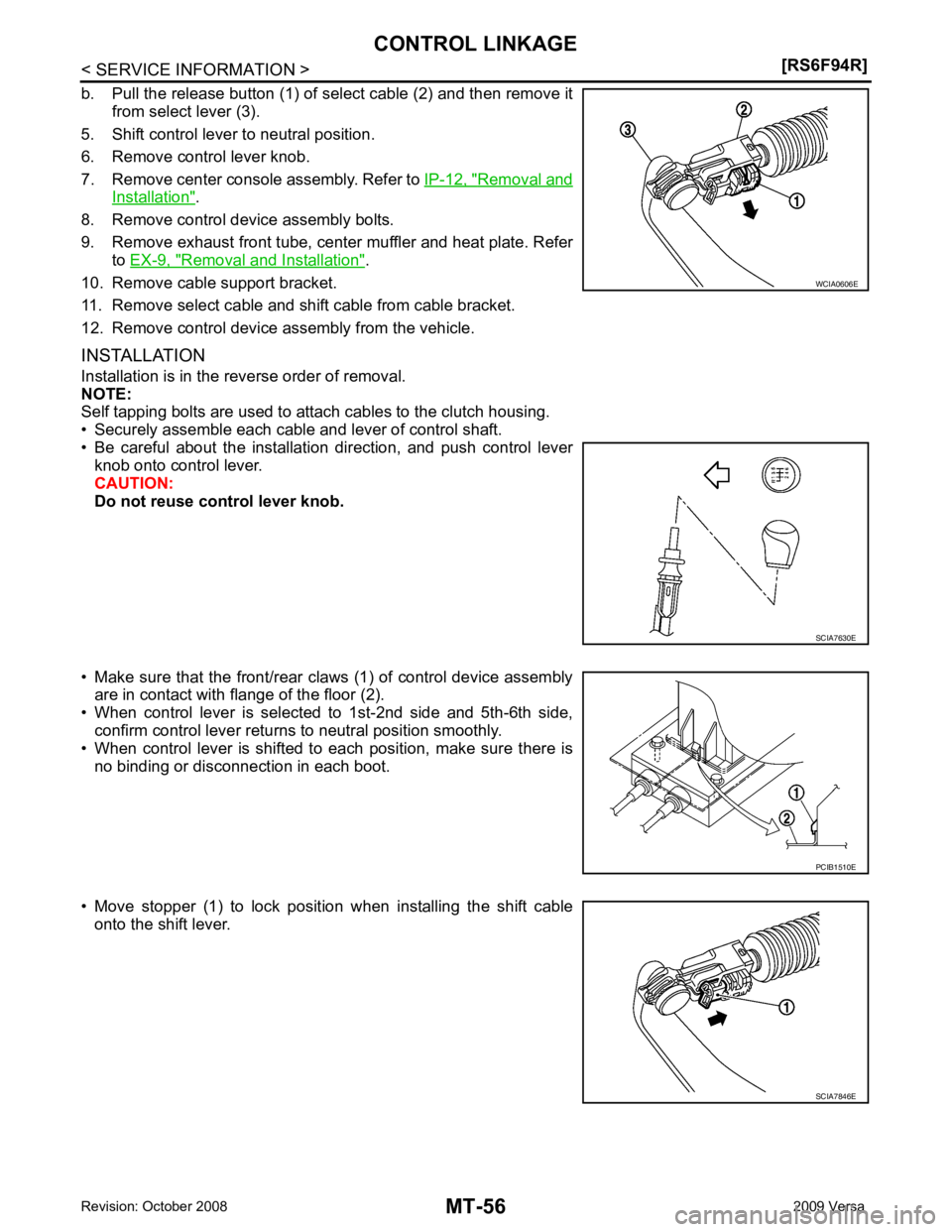
Removal and
Installation " .
8. Remove control device assembly bolts.
9. Remove exhaust front tube, center muffler and heat plate. Refer to EX-9, " Removal and Installation " .
10. Remove cable support bracket.
11. Remove select cable and shift cable from cable bracket.
12. Remove control device assembly from the vehicle.
INSTALLATION
Installation is in the reverse order of removal.
NOTE:
Self tapping bolts are used to attach cables to the clutch housing.
• Securely assemble each cable and lever of control shaft.
• Be careful about the installation direction, and push control lever knob onto control lever.
CAUTION:
Do not reuse control lever knob.
• Make sure that the front/rear claws (1) of control device assembly are in contact with flange of the floor (2).
• When control lever is selected to 1st-2nd side and 5th-6th side,
confirm control lever returns to neutral position smoothly.
• When control lever is shifted to each position, make sure there is
no binding or disconnection in each boot.
• Move stopper (1) to lock position when installing the shift cable onto the shift lever. SCIA7630E
SCIA7846E
Page 3851 of 4331
MT
N
O P
AIR BREATHER HOSE
Removal and Installation INFOID:0000000004305277
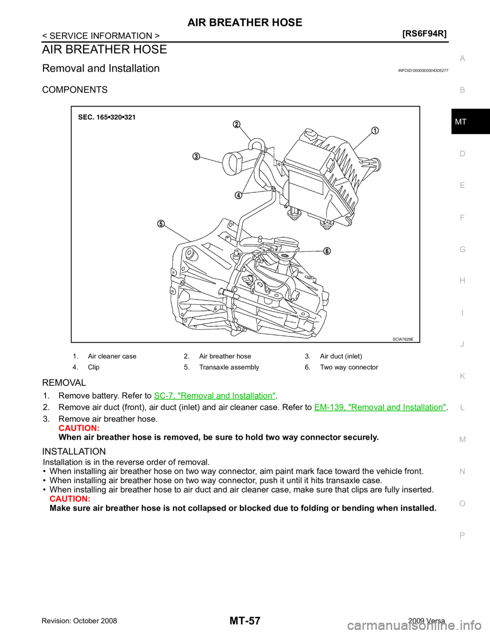
COMPONENTS
REMOVAL 1. Remove battery. Refer to SC-7, " Removal and Installation " .
2. Remove air duct (front), air duct (inlet) and air cleaner case. Refer to EM-139, " Removal and Installation " .
3. Remove air breather hose. CAUTION:
When air breather hose is removed, be su re to hold two way connector securely.
INSTALLATION Installation is in the reverse order of removal.
• When installing air breather hose on two way connector, aim paint mark face toward the vehicle front.
• When installing air breather hose on two way connec tor, push it until it hits transaxle case.
• When installing air breather hose to air duct and air cleaner case, make sure that clips are fully inserted. CAUTION:
Make sure air breather hose is not collapsed or bl ocked due to folding or bending when installed.
1. Air cleaner case 2. Air breather hose 3. Air duct (inlet)
4. Clip 5. Transaxle assembly 6. Two way connector