Page 3870 of 4331
![NISSAN LATIO 2009 Service Repair Manual MT-76< SERVICE INFORMATION >
[RS6F94R]
INPUT SHAFT AND GEARS
INPUT SHAFT AND GEARS
Disassembly and Assembly INFOID:0000000004305280
GENERAL PRECAUTIONS
• Never reuse snap ring.
• Secure input shaf NISSAN LATIO 2009 Service Repair Manual MT-76< SERVICE INFORMATION >
[RS6F94R]
INPUT SHAFT AND GEARS
INPUT SHAFT AND GEARS
Disassembly and Assembly INFOID:0000000004305280
GENERAL PRECAUTIONS
• Never reuse snap ring.
• Secure input shaf](/manual-img/5/57359/w960_57359-3869.png)
MT-76< SERVICE INFORMATION >
[RS6F94R]
INPUT SHAFT AND GEARS
INPUT SHAFT AND GEARS
Disassembly and Assembly INFOID:0000000004305280
GENERAL PRECAUTIONS
• Never reuse snap ring.
• Secure input shaft in a vise with backplate, and then remove gears and snap rings.
• For installation and removal of snap ring, set snap ring pliers and flat pliers at both sides of snap ring. While expanding snap ring
with snap ring pliers, move snap ring with flat pliers.
• Disassemble gear components putting direction marks on the parts that do not affect any functions.
DISASSEMBLY
1. Remove input shaft rear bearing bolt (1) using Tool (A).
2. Remove input shaft rear bearing (1) according to the following procedures.
a. Set a suitable puller to input shaft rear bearing.
b. Remove input shaft rear bearing using a suitable drift (A).
3. Remove spacer (1), 6th input gear (2), needle bearing, 6th baulk ring, and 5th-6th synchronizer hub assembly (3).
4. Remove insert keys and 5th-6th coupling sleeve from 5th-6th synchronizer hub. SCIA1755J
Tool number A: KV32300QAM ( — )
JPDIC0449ZZ
JPDIC0111ZZ
PCIB1750E
Page 3872 of 4331
![NISSAN LATIO 2009 Service Repair Manual MT-78< SERVICE INFORMATION >
[RS6F94R]
INPUT SHAFT AND GEARS
• Damage, peeling, bend, uneven wear, and distortion of shaft.
• Excessive wear, damage, and peeling of gear.
Synchronizer
• Synchron NISSAN LATIO 2009 Service Repair Manual MT-78< SERVICE INFORMATION >
[RS6F94R]
INPUT SHAFT AND GEARS
• Damage, peeling, bend, uneven wear, and distortion of shaft.
• Excessive wear, damage, and peeling of gear.
Synchronizer
• Synchron](/manual-img/5/57359/w960_57359-3871.png)
MT-78< SERVICE INFORMATION >
[RS6F94R]
INPUT SHAFT AND GEARS
• Damage, peeling, bend, uneven wear, and distortion of shaft.
• Excessive wear, damage, and peeling of gear.
Synchronizer
• Synchronizer hub and coupling sleeve Check the following items and replace if necessary.
- Breakage, damage, and unusual wear on contact surface of cou-
pling sleeve, synchronizer hub, and insert key.
- Coupling sleeve and synchronizer hub move smoothly.
• Baulk ring Check contact surface of baulk ring cam and insert key for exces-
sive wear, uneven wear, bend, and damage. Replace if necessary.
Bearing
Check bearing for damage and unsmooth rotation. Replace if neces-
sary.
ASSEMBLY
Note the following procedures, and assemble in the reverse order of disassembly.
CAUTION:
• Replace transaxle assembly when replacing input shaft.
• Never reuse snap ring.
• Check that snap ring is securely installed in a groove.
• Replace 3rd-4th coupling sleeve and 3rd-4th synchronizer hub as a set. SCIA7736E
SCIA1753J
SCIA0608J
MTF0041D
Page 3875 of 4331
![NISSAN LATIO 2009 Service Repair Manual MAINSHAFT AND GEARS
MT-81
< SERVICE INFORMATION >
[RS6F94R] D
E
F
G H
I
J
K L
M A
B MT
N
O P
MAINSHAFT AND GEARS
Disassembly and Assembly INFOID:0000000004305281
GENERAL PRECAUTIONS • Never reuse sn NISSAN LATIO 2009 Service Repair Manual MAINSHAFT AND GEARS
MT-81
< SERVICE INFORMATION >
[RS6F94R] D
E
F
G H
I
J
K L
M A
B MT
N
O P
MAINSHAFT AND GEARS
Disassembly and Assembly INFOID:0000000004305281
GENERAL PRECAUTIONS • Never reuse sn](/manual-img/5/57359/w960_57359-3874.png)
MAINSHAFT AND GEARS
MT-81
< SERVICE INFORMATION >
[RS6F94R] D
E
F
G H
I
J
K L
M A
B MT
N
O P
MAINSHAFT AND GEARS
Disassembly and Assembly INFOID:0000000004305281
GENERAL PRECAUTIONS • Never reuse snap ring.
• Secure mainshaft in a vise with backplate, and then remove gears and snap rings.
• For installation and removal of snap ring, set snap ring pliers and flat pliers at both sides of snap ring. While expanding snap ring
with snap ring pliers, move snap ring with flat pliers.
• Disassemble gear components putting direction marks on the parts that never affect any functions.
DISASSEMBLY 1. Remove snap ring (1) using suitable tool.
2. Remove 6th main gear (1) and mainshaft rear bearing inner race (2) according to the following procedures.
a. Set a suitable puller to 6th main gear.
b. Remove mainshaft rear bearing inner race and 6th main gear using the Tool (A).
3. Remove 4th main gear (1) and 5th main gear (2) according to the following procedures.
a. Set a suitable tool to 4th main gear.
b. Remove 5th main gear and 4th main gear using Tool (A).
4. Remove mainshaft adjusting shim. SCIA1755J
PCIB1745E
Tool number A: ST33052000 ( — )
PCIB1744E
Tool number A: ST33052000 ( — )
PCIB1743E
Page 3881 of 4331

MT
N
O P
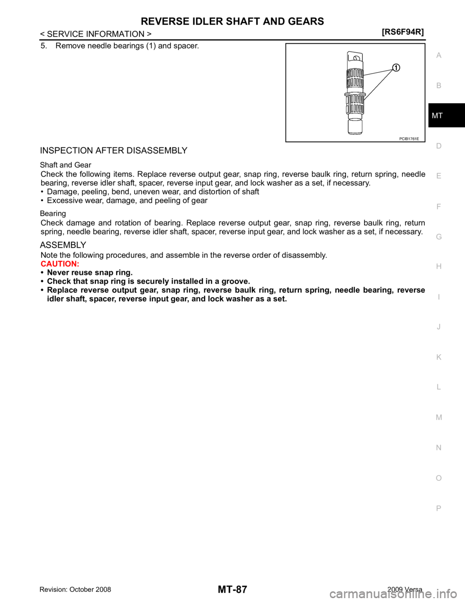
5. Remove needle bearings (1) and spacer.
INSPECTION AFTER DISASSEMBLY
Shaft and Gear Check the following items. Replace reverse output gear , snap ring, reverse baulk ring, return spring, needle
bearing, reverse idler shaft, spacer, reverse i nput gear, and lock washer as a set, if necessary.
• Damage, peeling, bend, uneven wear, and distortion of shaft
• Excessive wear, damage, and peeling of gear
Bearing Check damage and rotation of bearing. Replace revers e output gear, snap ring, reverse baulk ring, return
spring, needle bearing, reverse idler shaft, spacer, reve rse input gear, and lock washer as a set, if necessary.
ASSEMBLY Note the following procedures, and assemble in the reverse order of disassembly.
CAUTION:
• Never reuse snap ring.
• Check that snap ring is secu rely installed in a groove.
• Replace reverse output gear, snap ring, reverse baul k ring, return spring, needle bearing, reverse
idler shaft, spacer, reverse input gear, and lock washer as a set.
Page 3947 of 4331
Component Parts " .
2. Remove side ventilator duct (right). Refer to MTC-69, " Removal and Installation " .
3. Disconnect blower motor connector (1).
4. Push the flange holding hook (A) toward the blower motor (2), then rotate the blower motor (2) clockwise and remove it from
the A/C unit assembly.
CAUTION:
When blower fan and blower motor are assembled, the bal-
ance is adjusted, do not di sassemble to replace the individ-
ual parts.
INSTALLATION
Installation is in the reverse order of removal.
CAUTION:
Rotate the blower motor until the blower motor fl ange holding hook locks securely into the A/C unit
assembly.
Page 3953 of 4331

MTC-68< SERVICE INFORMATION >
AIR CONDITIONER FILTER
AIR CONDITIONER FILTER
Removal and Installation INFOID:0000000004307087
FUNCTION
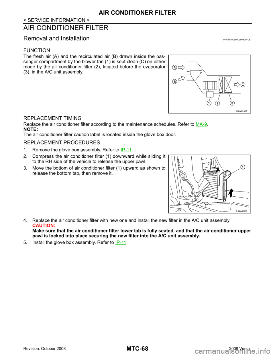
The fresh air (A) and the recirculated air (B) drawn inside the pas-
senger compartment by the blower fan (1) is kept clean (C) on either
mode by the air conditioner filter (2), located before the evaporator
(3), in the A/C unit assembly.
REPLACEMENT TIMING
Replace the air conditioner filter accord ing to the maintenance schedules. Refer to MA-9 .
NOTE:
The air conditioner filter caution label is located inside the glove box door.
REPLACEMENT PROCEDURES
1. Remove the glove box assembly. Refer to IP-11 .
2. Compress the air conditioner filter (1) downward while sliding it to the RH side of the vehicle to release the upper pawl.
3. Move the bottom of air conditioner filter (1) upward as shown to release the bottom tab, then remove it.
4. Replace the air conditioner filter with new one and install the new filter in the A/C unit assembly. CAUTION:
Make sure that the air conditioner filter lower tab is fully seated, and that the air conditioner upper
pawl is locked into place securing the ne w filter into the A/C unit assembly.
5. Install the glove box assembly. Refer to IP-11 . WJIA2253E
SJIA0652E
Page 3970 of 4331

MTC
N
O P
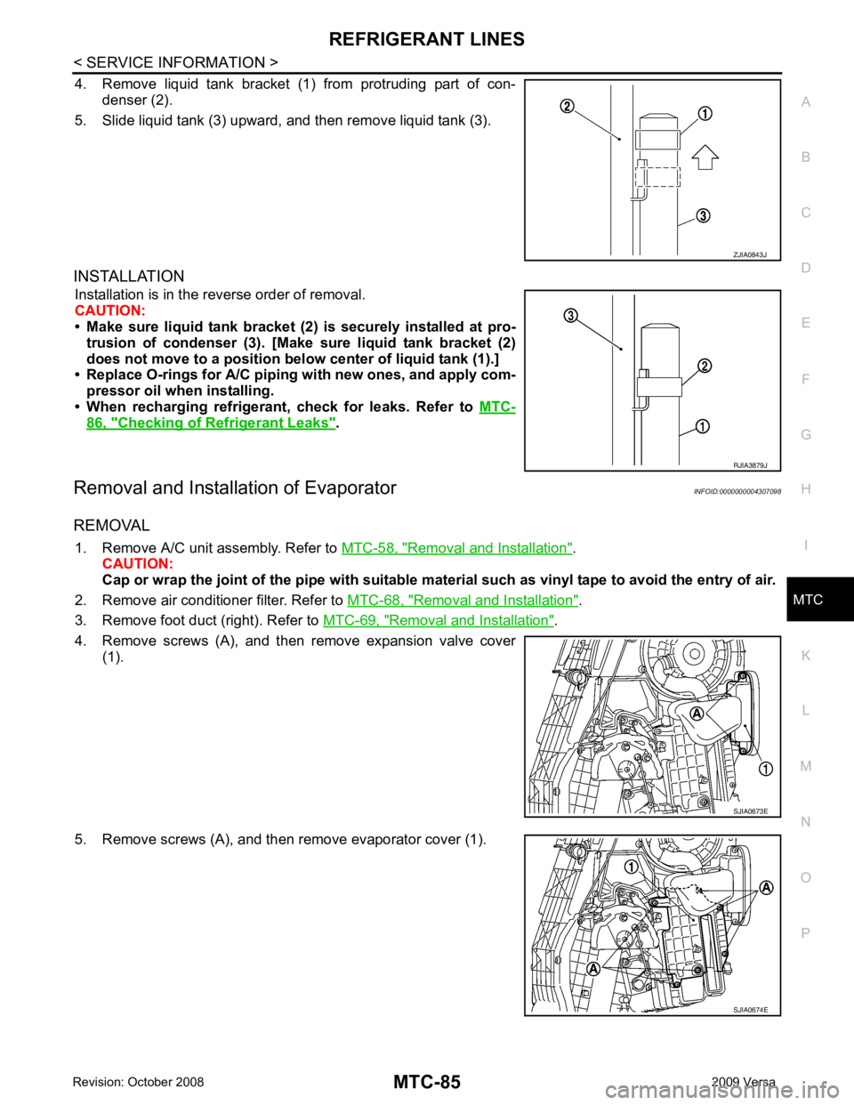
4. Remove liquid tank bracket (1
) from protruding part of con-
denser (2).
5. Slide liquid tank (3) upward, and then remove liquid tank (3).
INSTALLATION Installation is in the reverse order of removal.
CAUTION:
• Make sure liquid tank bracket (2) is securely installed at pro-
trusion of condenser (3). [Make sure liquid tank bracket (2)
does not move to a position belo w center of liquid tank (1).]
• Replace O-rings for A/C piping with new ones, and apply com-
pressor oil when installing.
• When recharging refrigerant, check for leaks. Refer to MTC-86, " Checking of Refrigerant Leaks " .
Removal and Installation of Evaporator INFOID:0000000004307098
REMOVAL 1. Remove A/C unit assembly. Refer to MTC-58, " Removal and Installation " .
CAUTION:
Cap or wrap the joint of the pipe with suitable ma terial such as vinyl tape to avoid the entry of air.
2. Remove air conditioner filter. Refer to MTC-68, " Removal and Installation " .
3. Remove foot duct (right). Refer to MTC-69, " Removal and Installation " .
4. Remove screws (A), and then remove expansion valve cover (1).
5. Remove screws (A), and then remove evaporator cover (1). RJIA3879J
Page 3974 of 4331

MTC
N
O P
Check all around the service valves. Ensure service valve caps are secured on the service valves (to
prevent leaks).
NOTE:
After removing A/C manifold gauge set from service va lves, wipe any residue from valves to prevent any
false readings by leak detector.
• Cooling unit (Evaporator)
With engine OFF, turn blower fan on “High” for at least 15 seconds to dissipate any refrigerant trace in
the cooling unit. Wait a minimum of 10 minutes ac cumulation time (refer to the manufacturer’s recom-
mended procedure for actual wait time) before inserting the leak detector probe into the drain hose.
Keep the probe inserted for at least 10 seconds. Use c aution not to contaminate the probe tip with water
or dirt that may be in the drain hose.
5. If a leak detector detects a leak, verify at least once by blowing compressed air into area of suspected
leak, then repeat check as outlined above.
6. Do not stop when one leak is found. Continue to check for additional leaks at all system components.
If no leaks are found, perform steps 7-10.
7. Start engine.
8. Set the heater A/C control as follows;
a. A/C switch: ON
b. Mode control dial position: VENT (Ventilation)
c. Intake door lever position: Recirculation
d. Max. cold temperature
e. Fan speed: High
9. Run engine at 1,500 rpm for at least 2 minutes.
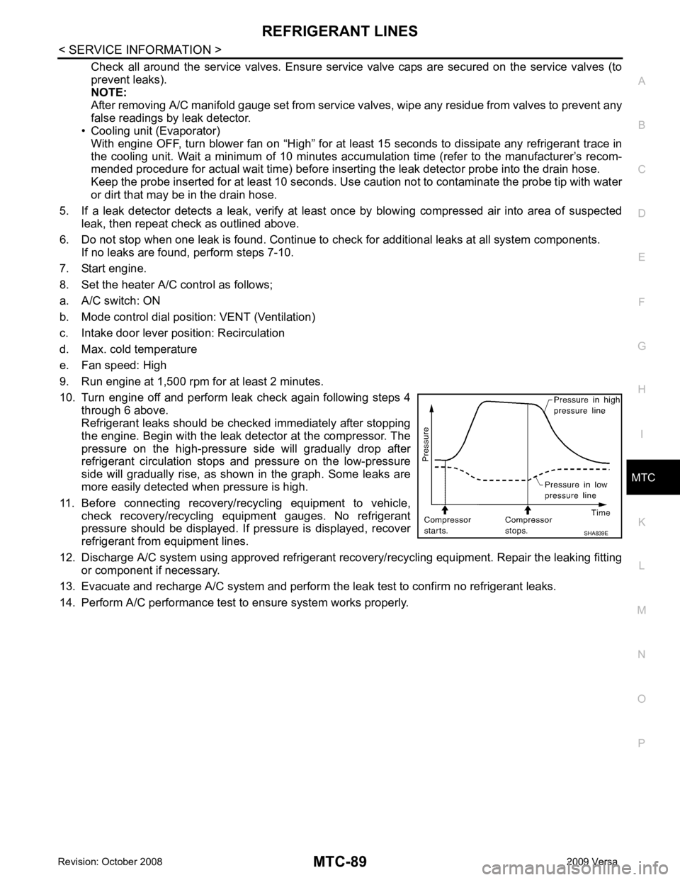
10. Turn engine off and perform leak check again following steps 4 through 6 above.
Refrigerant leaks should be chec ked immediately after stopping
the engine. Begin with the leak detector at the compressor. The
pressure on the high-pressure side will gradually drop after
refrigerant circulation stops and pressure on the low-pressure
side will gradually rise, as shown in the graph. Some leaks are
more easily detected when pressure is high.
11. Before connecting recovery/recycling equipment to vehicle, check recovery/recycling equipment gauges. No refrigerant
pressure should be displayed. If pressure is displayed, recover
refrigerant from equipment lines.
12. Discharge A/C system using approved refrigerant reco very/recycling equipment. Repair the leaking fitting
or component if necessary.
13. Evacuate and recharge A/C system and perform the l eak test to confirm no refrigerant leaks.
14. Perform A/C performance test to ensure system works properly.