2009 NISSAN LATIO ignition
[x] Cancel search: ignitionPage 1137 of 4331
![NISSAN LATIO 2009 Service Repair Manual PRECAUTIONS
CVT-193
< SERVICE INFORMATION >
[RE0F08B] D
E
F
G H
I
J
K L
M A
B CVT
N
O P
•
Before connecting or disconn ecting the TCM harness connec-
tor, turn ignition switch OF F and disconn NISSAN LATIO 2009 Service Repair Manual PRECAUTIONS
CVT-193
< SERVICE INFORMATION >
[RE0F08B] D
E
F
G H
I
J
K L
M A
B CVT
N
O P
•
Before connecting or disconn ecting the TCM harness connec-
tor, turn ignition switch OF F and disconn](/manual-img/5/57359/w960_57359-1136.png)
PRECAUTIONS
CVT-193
< SERVICE INFORMATION >
[RE0F08B] D
E
F
G H
I
J
K L
M A
B CVT
N
O P
•
Before connecting or disconn ecting the TCM harness connec-
tor, turn ignition switch OF F and disconnect negative battery
cable. Because battery voltage is applied to TCM even if igni-
tion switch is turned OFF.
• When connecting or disconnect ing pin connectors into or
from TCM, take care not to damage pin terminals (bend or
break).
When connecting pin connectors make sure that there are not
any bends or breaks on TCM pin terminal.
• Before replacing TCM, perform TCM input/output signal
inspection and make sure whether TCM functions properly or
not. CVT-228, " TCM Terminal and Reference Value " .
• After performing each TROUBL E DIAGNOSIS, perform “DTC
Confirmation Procedure”.
If the repair is completed the DTC should not be displayed in
the “DTC Confirmation Procedure”.
• Always use the specified br and of CVT fluid. Refer to MA-14, " Flu-
ids and Lubricants " .
• Use lint-free paper, not cloth rags, during work.
• After replacing the CVT fluid, dispose of the waste oil using the methods prescribed by law, ordinance, etc.
Service Notice or Precaution INFOID:0000000004305567
CVT FLUID COOLER SERVICE If CVT fluid contains friction material (clutches, brakes , etc.), or if an CVT is replaced, inspect and clean the
CVT fluid cooler mounted in the radiator or replace t he radiator. Flush cooler lines using cleaning solvent and
compressed air after repair. For CVT fluid cooler cleaning procedure, refer to CVT-197, " CVT Fluid Cooler
Cleaning " . For radiator replacement, refer to
CO-38 .
OBD-II SELF-DIAGNOSIS SEF289H
SEF291H
MEF040DA
SEF217U
Page 1154 of 4331

CONSULT-III F
unction (ENGINE) " .
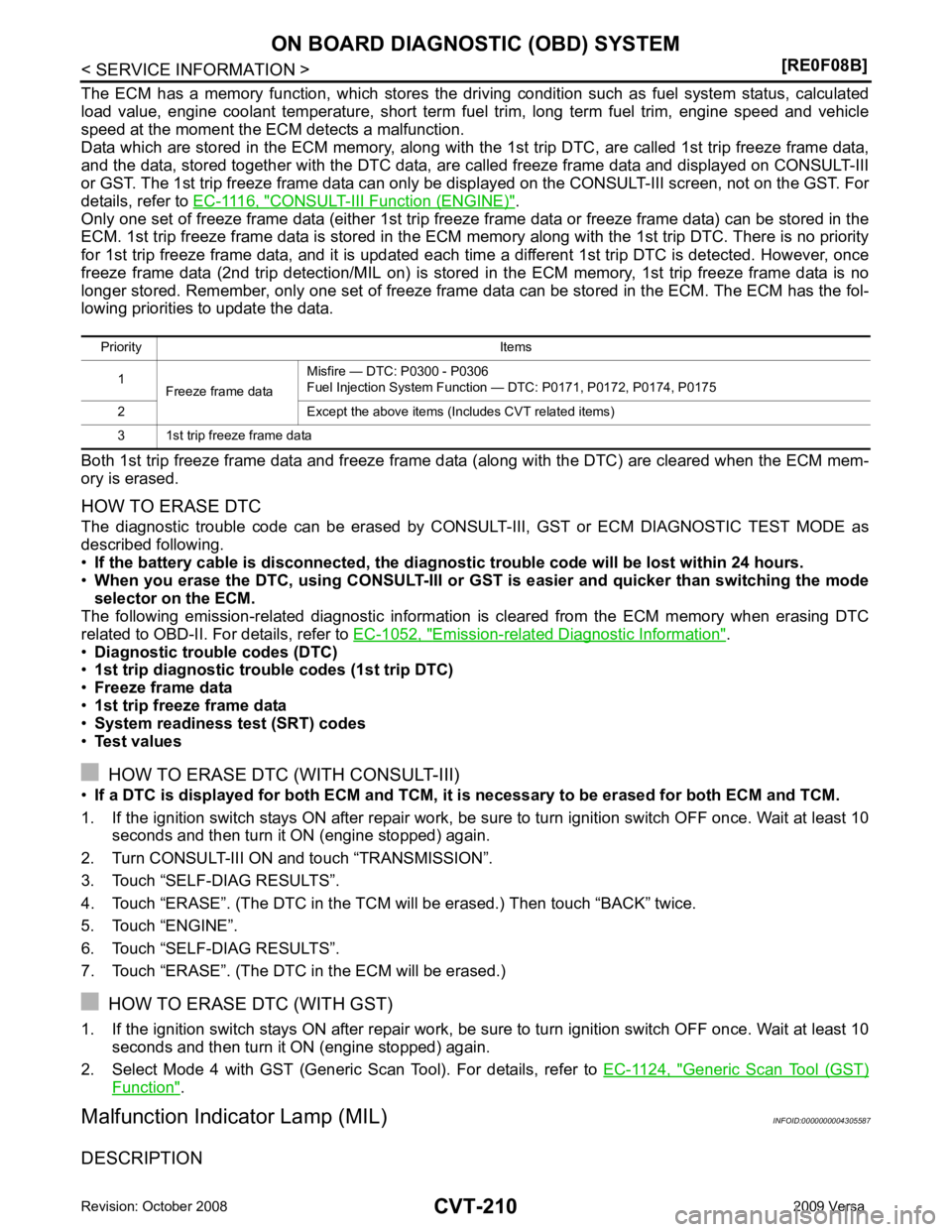
Only one set of freeze frame data (either 1st trip freez e frame data or freeze frame data) can be stored in the
ECM. 1st trip freeze frame data is stored in the ECM me mory along with the 1st trip DTC. There is no priority
for 1st trip freeze frame data, and it is updated each time a different 1st trip DTC is detected. However, once
freeze frame data (2nd trip detection/MIL on) is stored in the ECM memory, 1st trip freeze frame data is no
longer stored. Remember, only one set of freeze frame data can be stored in the ECM. The ECM has the fol-
lowing priorities to update the data.
Both 1st trip freeze frame data and freeze frame dat a (along with the DTC) are cleared when the ECM mem-
ory is erased.
HOW TO ERASE DTC
The diagnostic trouble code can be erased by CONSULT- III, GST or ECM DIAGNOSTIC TEST MODE as
described following.
• If the battery cable is disconnected, the diagnosti c trouble code will be lost within 24 hours.
• When you erase the DTC, using CONSULT-III or GS T is easier and quicker than switching the mode
selector on the ECM.
The following emission-related diagnostic information is cleared from the ECM memory when erasing DTC
related to OBD-II. For details, refer to EC-1052, " Emission-related Diagnostic Information " .
• Diagnostic trouble codes (DTC)
• 1st trip diagnostic trou ble codes (1st trip DTC)
• Freeze frame data
• 1st trip freeze frame data
• System readiness test (SRT) codes
• Test values
HOW TO ERASE DTC (WITH CONSULT-III)
• If a DTC is displayed for both ECM and TCM, it is necessary to be erased for both ECM and TCM.
1. If the ignition switch stays ON after repair work, be sure to turn ignition switch OFF once. Wait at least 10 seconds and then turn it ON (engine stopped) again.
2. Turn CONSULT-III ON and touch “TRANSMISSION”.
3. Touch “SELF-DIAG RESULTS”.
4. Touch “ERASE”. (The DTC in the TCM will be erased.) Then touch “BACK” twice.
5. Touch “ENGINE”.
6. Touch “SELF-DIAG RESULTS”.
7. Touch “ERASE”. (The DTC in the ECM will be erased.)
HOW TO ERASE DTC (WITH GST)
1. If the ignition switch stays ON after repair work, be sure to turn ignition switch OFF once. Wait at least 10 seconds and then turn it ON (engine stopped) again.
2. Select Mode 4 with GST (Generic Scan Tool). For details, refer to EC-1124, " Generic Scan Tool (GST)
Function " .
Malfunction Indicator Lamp (MIL) INFOID:0000000004305587
DESCRIPTION Priority Items
1 Freeze frame data Misfire — DTC: P0300 - P0306
Fuel Injection System Function — DTC: P0171, P0172, P0174, P0175
2 Except the above items (Includes CVT related items)
3 1st trip freeze frame data
Page 1155 of 4331
![NISSAN LATIO 2009 Service Repair Manual ON BOARD DIAGNOSTIC (OBD) SYSTEM
CVT-211
< SERVICE INFORMATION >
[RE0F08B] D
E
F
G H
I
J
K L
M A
B CVT
N
O P
The MIL is located on the instrument panel.
1. The MIL will light up when the ignition swit NISSAN LATIO 2009 Service Repair Manual ON BOARD DIAGNOSTIC (OBD) SYSTEM
CVT-211
< SERVICE INFORMATION >
[RE0F08B] D
E
F
G H
I
J
K L
M A
B CVT
N
O P
The MIL is located on the instrument panel.
1. The MIL will light up when the ignition swit](/manual-img/5/57359/w960_57359-1154.png)
ON BOARD DIAGNOSTIC (OBD) SYSTEM
CVT-211
< SERVICE INFORMATION >
[RE0F08B] D
E
F
G H
I
J
K L
M A
B CVT
N
O P
The MIL is located on the instrument panel.
1. The MIL will light up when the ignition switch is turned ON with- out the engine running. This is a bulb check.
• If the MIL does not light up, refer to DI-20, " Schematic " , or see
EC-1532, " Wiring Diagram " .
2. When the engine is start ed, the MIL should go off.
If the MIL remains on, the on board diagnostic system has
detected an engine system malfunction. SEF217U
Page 1157 of 4331
![NISSAN LATIO 2009 Service Repair Manual TROUBLE DIAGNOSIS
CVT-213
< SERVICE INFORMATION >
[RE0F08B] D
E
F
G H
I
J
K L
M A
B CVT
N
O P
If an unexpected signal is sent from the solenoid to t
he TCM, the CVT lock-up select solenoid is turned O NISSAN LATIO 2009 Service Repair Manual TROUBLE DIAGNOSIS
CVT-213
< SERVICE INFORMATION >
[RE0F08B] D
E
F
G H
I
J
K L
M A
B CVT
N
O P
If an unexpected signal is sent from the solenoid to t
he TCM, the CVT lock-up select solenoid is turned O](/manual-img/5/57359/w960_57359-1156.png)
TROUBLE DIAGNOSIS
CVT-213
< SERVICE INFORMATION >
[RE0F08B] D
E
F
G H
I
J
K L
M A
B CVT
N
O P
If an unexpected signal is sent from the solenoid to t
he TCM, the CVT lock-up select solenoid is turned OFF to
cancel the lock-up.
TCM Power Supply (Memory Back-up) Transaxle assembly is protected by limiting the engine torque when the memory back-up power supply (for
controlling) from the battery is not supplied to TCM. Normal statues is restored when turning the ignition switch
OFF to ON after the normal power supply.
How to Perform Trouble Diagnosis for Quick and Accurate Repair INFOID:0000000004305590
INTRODUCTION The TCM receives a signal from the vehicle speed sensor , PNP switch and provides shift control or lock-up
control via CVT solenoid valves.
The TCM also communicates with the ECM by means of a signal
sent from sensing elements used wit h the OBD-related parts of the
CVT system for malfunction-diagnos tic purposes. The TCM is capa-
ble of diagnosing malfunctioning parts while the ECM can store mal-
functions in its memory.
Input and output signals must always be correct and stable in the
operation of the CVT system. The CVT system must be in good
operating condition and be free of valve seizure, solenoid valve mal-
function, etc.
It is much more difficult to diagnose an error that occurs intermit-
tently rather than continuously. Most intermittent errors are caused
by poor electric connections or impr oper wiring. In this case, careful
checking of suspected circuits may help prevent the replacement of
good parts.
A visual check only may not find t he cause of the errors. A road test
with CONSULT-III (or GST) or a circuit tester connected should be
performed. Follow the "WORK FLOW" .
Before undertaking actual checks, take a few minutes to talk with a
customer who approaches with a driveability complaint. The cus-
tomer can supply good information about such errors, especially
intermittent ones. Find out what symptoms are present and under
what conditions they occur. A “DIAGNOSTIC WORKSHEET” as
shown on the example (Refer to "Diagnostic Worksheet Chart" )
should be used.
Start your diagnosis by looking for “conventional” errors first. This will
help troubleshoot driveability errors on an electronically controlled
engine vehicle.
Also check related Service bulletins.
WORK FLOW A good understanding of the malfunction conditions can make troubleshooting faster and more accurate.
In general, each customer feels differently about a malf unction. It is important to fully understand the symp-
toms or conditions for a customer complaint.
Make good use of the two sheets provided, "Informati on From Customer" and "Diagnostic Worksheet Chart" ,
to perform the best troubleshooting possible.
Work Flow Chart SAT631IB
SAT632I
SEF234G
Page 1168 of 4331
![NISSAN LATIO 2009 Service Repair Manual CVT-224< SERVICE INFORMATION >
[RE0F08B]
TROUBLE DIAGNOSIS
• Before road test, familiarize yourself with all test procedures and items to check.
• Perform tests on all items until s NISSAN LATIO 2009 Service Repair Manual CVT-224< SERVICE INFORMATION >
[RE0F08B]
TROUBLE DIAGNOSIS
• Before road test, familiarize yourself with all test procedures and items to check.
• Perform tests on all items until s](/manual-img/5/57359/w960_57359-1167.png)
CVT-224< SERVICE INFORMATION >
[RE0F08B]
TROUBLE DIAGNOSIS
• Before road test, familiarize yourself with all test procedures and items to check.
• Perform tests on all items until s pecified symptom is found. Trou-
bleshoot items which check out No Good after road test.
CONSULT-III START PROCEDURE
• Using CONSULT-III, perform a cruise test and record the result.
• Print the result and ensure that shifts and lock-ups take place as per Shift Schedule.
1. Touch “DATA MONITOR” on “SELECT DIAG MODE” screen.
2. Touch “MAIN SIGNALS” to set recording condition.
3. See “Numerical Display”, “Barchart Display” or “Line Graph Display”.
4. Touch “START”.
5. When performing cruise test. Refer to CVT-226, " Cruise Test " .
6. After finishing cruise test part, touch “RECORD”.
7. Touch “STORE”.
8. Touch “BACK”.
9. Touch “DISPLAY”.
10. Touch “PRINT”.
11. Check the monitor data printed out. Check before Engine Is Started INFOID:00000000043055951.
CHECK O/D OFF INDICATOR LAMP
1. Park vehicle on flat surface.
2. Move selector lever to “P” position.
3. Turn ignition switch OFF. Wait at least 5 seconds.
4. Turn ignition switch ON. (Do not start engine.)
Does O/D OFF indicator lamp come on for about 2 seconds? YES >> 1. Turn ignition switch OFF.
2. Perform self-diagnosis and note NG items.Refer to CVT-230, " CONSULT-III Function (TRANSMISSION) " .
3. Go to CVT-224, " Check at Idle " .
NO >> Stop “Road Test”. Go to CVT-325, " O/D OFF Indicator Lamp Does Not Come On " .
Check at Idle INFOID:00000000043055961.
CHECK STARTING THE ENGINE
1. Park vehicle on flat surface.
2. Move selector lever to “P” or “N” position.
3. Turn ignition switch OFF.
4. Turn ignition switch START.
Is engine started? SAT496G
Page 1173 of 4331

CVT
N
O P
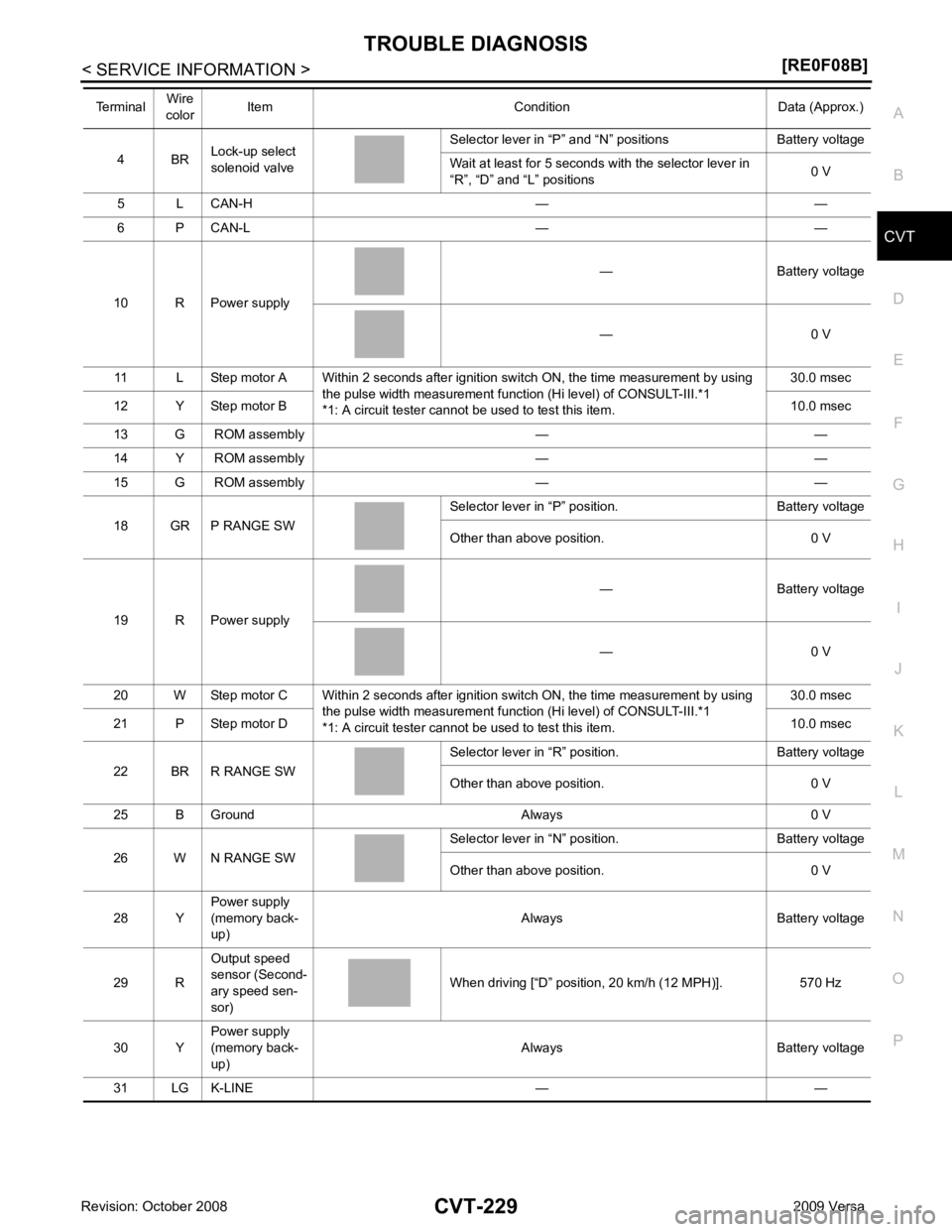
4 BR
Lock-up select
solenoid valve Selector lever in “P” and “N
” positions Battery voltage
Wait at least for 5 seconds with the selector lever in
“R”, “D” and “L” positions 0 V
5 L CAN-H — —
6 P CAN-L — —
10 R Power supply — Battery voltage
— 0 V
11 L Step motor A Within 2 seconds after ignition switch ON, the time measurement by using the pulse width measurement function (Hi level) of CONSULT-III.*1
*1: A circuit tester cannot be used to test this item. 30.0 msec
12 Y Step motor B 10.0 msec
13 G ROM assembly — —
14 Y ROM assembly — —
15 G ROM assembly — —
18 GR P RANGE SW Selector lever in “P” po
sition. Battery voltage
Other than above position. 0 V
19 R Power supply — Battery voltage
— 0 V
20 W Step motor C Within 2 seconds after ignition switch ON, the time measurement by using the pulse width measurement function (Hi level) of CONSULT-III.*1
*1: A circuit tester cannot be used to test this item. 30.0 msec
21 P Step motor D 10.0 msec
22 BR R RANGE SW Selector lever in “R” po
sition. Battery voltage
Other than above position. 0 V
25 B Ground Always 0 V
26 W N RANGE SW Selector lever in “N” po
sition. Battery voltage
Other than above position. 0 V
28 Y Power supply
(memory back-
up) Always Battery voltage
29 R Output speed
sensor (Second-
ary speed sen-
sor) When driving [“D” position, 20 km/h (12 MPH)]. 570 Hz
30 Y Power supply
(memory back-
up) Always Battery voltage
31 LG K-LINE — —
Terminal
Wire
color Item Condition Data (Approx.)
Page 1175 of 4331

CVT
N
O P
PRI SPEED SEN During driving (lock-up ON) A
pproximately matches the engine speed.
ENG SPEED SIG Engine running Closely matches the tachometer reading.
SEC HYDR SEN “N” position idle 1.0 V
ATF TEMP SEN When CVT fluid temperature is 20
°C (68 °F). 2.0 V
When CVT fluid temperature is 80 °C (176 °F). 1.0 V
VIGN SEN Ignition switch: ON Battery voltage
VEHICLE SPEED During driving Approximately matches the speedometer
reading.
PRI SPEED During driving (lock-up ON) App roximately matches the engine speed.
SEC SPEED During driving 50 X Approximately matches the speedom-
eter reading.
ENG SPEED Engine running Closely matches the tachometer reading.
GEAR RATIO During driving 2.56 - 0.43
ACC PEDAL OPEN Released accelerator pedal - Fully depressed
accelerator pedal 0.0/8 - 8.0/8
SEC PRESS “N” position idle 0.8 MPa
STM STEP During driving −20 step - 180 step
ISOLT1 Lock-up OFF 0.0 A
Lock-up ON 0.7 A
ISOLT2 Release your foot from the accelerator pedal. 0.8 A
Press the accelerator pedal all the way down. 0.0 A
ISOLT3 Secondary pressure low - Secondary pressure
high. 0.8 - 0.0 A
SOLMON1 Lock-up OFF 0.0 A
Lock-up ON 0.7 A
SOLMON2 “N” position idle 0.8 A
When stalled 0.3 - 0.6 A
SOLMON3 “N” position idle 0.6 - 0.7 A
When stalled 0.4 - 0.6 A
P POSITION SW Selector lever in “P” position ON
Other than the above position OFF
R POSITION SW Selector lever in “R” position ON
Other than the above position OFF
N POSITION SW Selector lever in “N” position ON
Other than the above position OFF
D POSITION SW Selector lever in “D” position ON
Other than the above position OFF
L POSITION SW Selector lever in “L” position ON
Other than the above position OFF
BRAKE SW Depressed brake pedal ON
Released brake pedal OFF
FULL SW Fully depressed accelerator pedal ON
Released accelerator pedal OFF
IDLE SW Released accelerator pedal ON
Fully depressed accelerator pedal OFF
Item name Condition Display value (Approx.)
Page 1185 of 4331

CVT
N
O P
DTC U1010 TRANSMISSION
CONTROL MODULE (CAN)
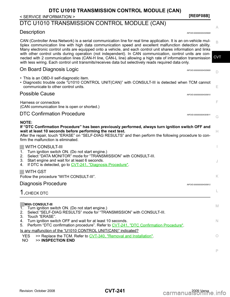
Description INFOID:0000000004305608
CAN (Controller Area Network) is a serial communication li ne for real time application. It is an on-vehicle mul-
tiplex communication line with high data communica tion speed and excellent malfunction detection ability.
Many electronic control units are equipped onto a vehicl e, and each control unit shares information and links
with other control units during operation (not independent ). In CAN communication, control units are con-
nected with 2 communication lines (CAN-H line, CAN-L li ne) allowing a high rate of information transmission
with less wiring. Each control unit transmits/recei ves data but selectively reads required data only.
On Board Diagnosis Logic INFOID:0000000004305609
• This is an OBD-II self-diagnostic item.
• Diagnostic trouble code “U1010 CONTROL UNIT(CAN)” with CONSULT-III is detected when TCM cannot
communicate to other control units.
Possible Cause INFOID:0000000004305610
Harness or connectors
(CAN communication line is open or shorted.)
DTC Confirmation Procedure INFOID:0000000004305611
NOTE:
If “DTC Confirmation Procedure” has been previously performed, alw ays turn ignition switch OFF and
wait at least 10 seconds before performing the next test.
After the repair, touch “ERASE” on “SELF-DIAG RESU LTS” and then perform the following procedure to con-
firm the malfunction is eliminated.
WITH CONSULT-III
1. Turn ignition switch ON. (Do not start engine.)
2. Select “DATA MONITOR” mode for “TRANSMISSION” with CONSULT-III.
3. Start engine and wait for at least 6 seconds.
4. If DTC is detected, go to CVT-241, " Diagnosis Procedure " .
WITH GST
Follow the procedure “WITH CONSULT-III”.
Diagnosis Procedure INFOID:0000000004305612DTC Confirmation Procedure " .
Is any malfunction of the “ U1010 CONTROL UNIT(CAN) ” indicated?
YES >> Replace the TCM. Refer to
CVT-340, " Removal and Installation " .
NO >> INSPECTION END