Page 4266 of 4331

WT
N
O P
CONTENTS
ROAD WHEELS & TIRES
SERVICE INFORMATION .. ..........................2
PRECAUTIONS .............................................. .....2
Precaution for Supplemental Restraint System
(SRS) "AIR BAG" and "SEAT BELT PRE-TEN-
SIONER" ............................................................. ......
2
Precaution Necessary fo r Steering Wheel Rota-
tion After Battery Disconnect ............................... ......
2
PREPARATION .............................................. .....4
Special Service Tool ........................................... ......4
Commercial Service Tool .................................... ......4
NOISE, VIBRATION AND HARSHNESS
(NVH) TROUBLESHOOTING ........................ .....5
NVH Troubleshooting Chart ................................ ......5
ROAD WHEEL ............................................... .....6
Inspection ............................................................ ......6
ROAD WHEEL TIRE ASSEMBLY ................. .....7
Balancing Wheels ............................................... ......7
Rotation ............................................................... ......7
TIRE PRESSURE MONITORING SYSTEM ... .....8
System Component ............................................. ......8
System Description ............................................. ......8
CAN COMMUNICATION ................................ ....10
System Description ............................................. ....10
TROUBLE DIAGNOSES ................................ ....11
Wiring Diagram- T/WARN - ................................. ....11
Terminal and Reference Value for BCM ............. ....11
ID Registration Procedure ................................... ....12 Transmitter Wake Up Oper
ation ..............................13
CONSULT-III Function (B CM) .................................13
How to Perform Trouble Diagnosis for Quick and
Accurate Repair ................................................... ....
14
Preliminary Check ............................................... ....15
Self-Diagnosis (With CONSULT-III) .................... ....16
Self-Diagnosis (Without CONSULT-III) ............... ....17
TROUBLE DIAGNOSIS FOR SELF-DIAG-
NOSTIC ITEMS ................................................. 19
Data from Transmitter Not Being Received ......... ....19
Transmitter Malfunction ....................................... ....19
Transmitter Pressure Malf unction ............................20
Vehicle Speed Signal .......................................... ....20
Vehicle Ignition Signal ......................................... ....21
TROUBLE DIAGNOSIS FOR SYMPTOMS ...... 22
Low Tire Pressure Warning Lamp Does Not Come
On When Ignition Switch Is Turned On ............... ....
22
Low Tire Pressure Warnin g Lamp Stays On When
Ignition Switch Is Turned On ............................... ....
22
Low Tire Pressure Warning Lamp Flashes When
Ignition Switch Is Turned On ............................... ....
23
Hazard Warning Lamps Flash When Ignition
Switch Is Turned On ............................................ ....
24
ID Registration Cannot Be Completed ....................24
REMOVAL AND INSTALLATION ..................... 25
Transmitter (Pressure Sens or) ................................25
SERVICE DATA AND SPECIFICATIONS
(SDS) ................................................................. 27
Road Wheel ......................................................... ....27
Tire ...................................................................... ....27
Page 4268 of 4331
WT
N
O P
5. When the repair work is completed, return the ignition switch to the
″LOCK ″ position before connecting
the battery cables. (At this time, the steering lock mechanism will engage.)
6. Perform a self-diagnosis check of al l control units using CONSULT-III.
Page 4270 of 4331

WT
N
O P
NOISE, VIBRATION AND HARSHN
ESS (NVH) TROUBLESHOOTING
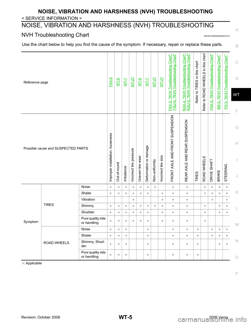
NVH Troubleshooting Chart INFOID:0000000004307315
Use the chart below to help you find t he cause of the symptom. If necessary, repair or replace these parts.
× : Applicable
Reference pageFAX-6WT-6WT-7WT-27WT-6WT-7WT-27WT-27
FAX-5, "
NVH Troubleshooting Chart
",
FSU-6, "
NVH Troubleshooting Chart
"
RAX-4, "
NVH Troubleshooting Chart
",
RSU-5, "
NVH Troubleshooting Chart
"
Refer to TIRES in this chart
Refer to ROAD WHEELS in this chart
FAX-5, "
NVH Troubleshooting Chart
"
BR-5, "
NVH Troubleshooting Chart
"
PS-5, "
NVH Troubleshooting Chart
" Possible cause and SUSPECTED PARTS
Improper installation, looseness
Out-of-round
Imbalance
Incorrect tire pressure
Uneven tire wear
Deformation or damage
Non-uniformity
Incorrect tire size
FRONT AXLE AND FRONT SUSPENSION
REAR AXLE AND REAR SUSPENSION
TIRES
ROAD WHEELS
DRIVE SHAFT
BRAKE
STEERING
Symptom TIRES Noise
× × × × × × × × × × × × ×
Shake × × × × × × × × × × × × ×
Vibration × × × × × ×
Shimmy × × × × × × × × × × × × ×
Shudder × × × × × × × × × × × ×
Poor quality ride
or handling × × × × × × × × × ×
ROAD WHEELS Noise
× × × × × × × × × ×
Shake × × × × × × × × × ×
Shimmy, Shud-
der × × × × × × × × ×
Poor quality ride
or handling × × × × × × ×
Page 4315 of 4331

WW
N
O P
Removal and Installation of
Front Wiper and Washer Switch INFOID:0000000004306930
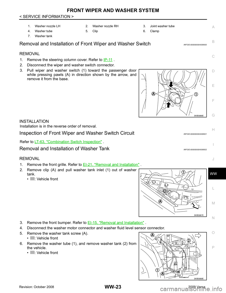
REMOVAL 1. Remove the steering column cover. Refer to IP-11 .
2. Disconnect the wiper and washer switch connector.
3. Pull wiper and washer switch (1) toward the passenger door while pressing pawls (A) in direction shown by the arrow, and
remove it from the base.
INSTALLATION Installation is in the reverse order of removal.
Inspection of Front Wiper and Washer Switch Circuit INFOID:0000000004306931
Refer to LT-63, " Combination Switch Inspection " .
Removal and Installation of Washer Tank INFOID:0000000004306932
REMOVAL 1. Remove the front grille. Refer to EI-21, " Removal and Installation " .
2. Remove clip (A) and pull washer tank inlet (1) out of washer tank.
• : Vehicle front
3. Remove the front bumper. Refer to EI-15, " Removal and Installation " .
4. Disconnect the washer motor connector and washer fluid level sensor connector.
5. Remove the washer tank screw (A). • : Vehicle front
6. Remove the washer tube (1), and remove washer tank (2) from the vehicle.
• : Vehicle front 1. Washer nozzle LH 2. Washer nozzle RH 3. Joint washer tube
4. Washer tube 5. Clip 6. Clamp
7. Washer tank