2009 NISSAN LATIO wheel
[x] Cancel search: wheelPage 424 of 4331
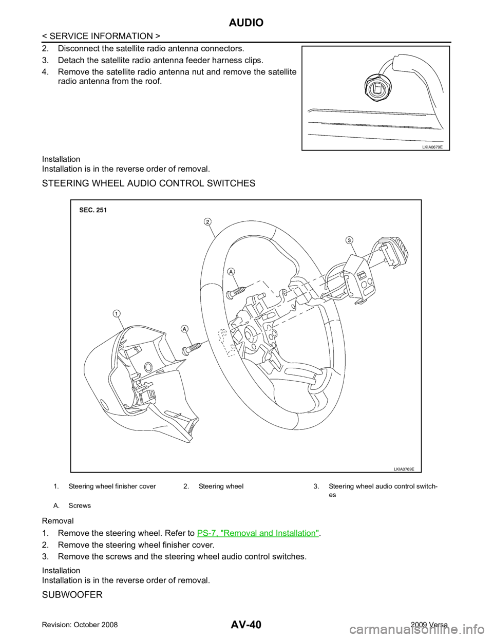
Removal and Installation " .
2. Remove the steering wheel finisher cover.
3. Remove the screws and the steering wheel audio control switches.
Installation
Installation is in the reverse order of removal.
SUBWOOFER
Page 429 of 4331
AV
N
O P
tooth cellular telephones may not be recognized by t
he Bluetooth control unit. When a cellular telephone or
the Bluetooth control unit is replaced, the telephone must be paired with the Bluetooth control unit. Different
cellular telephones may have different pairing procedures. Refer to the cellular telephone operating manual.
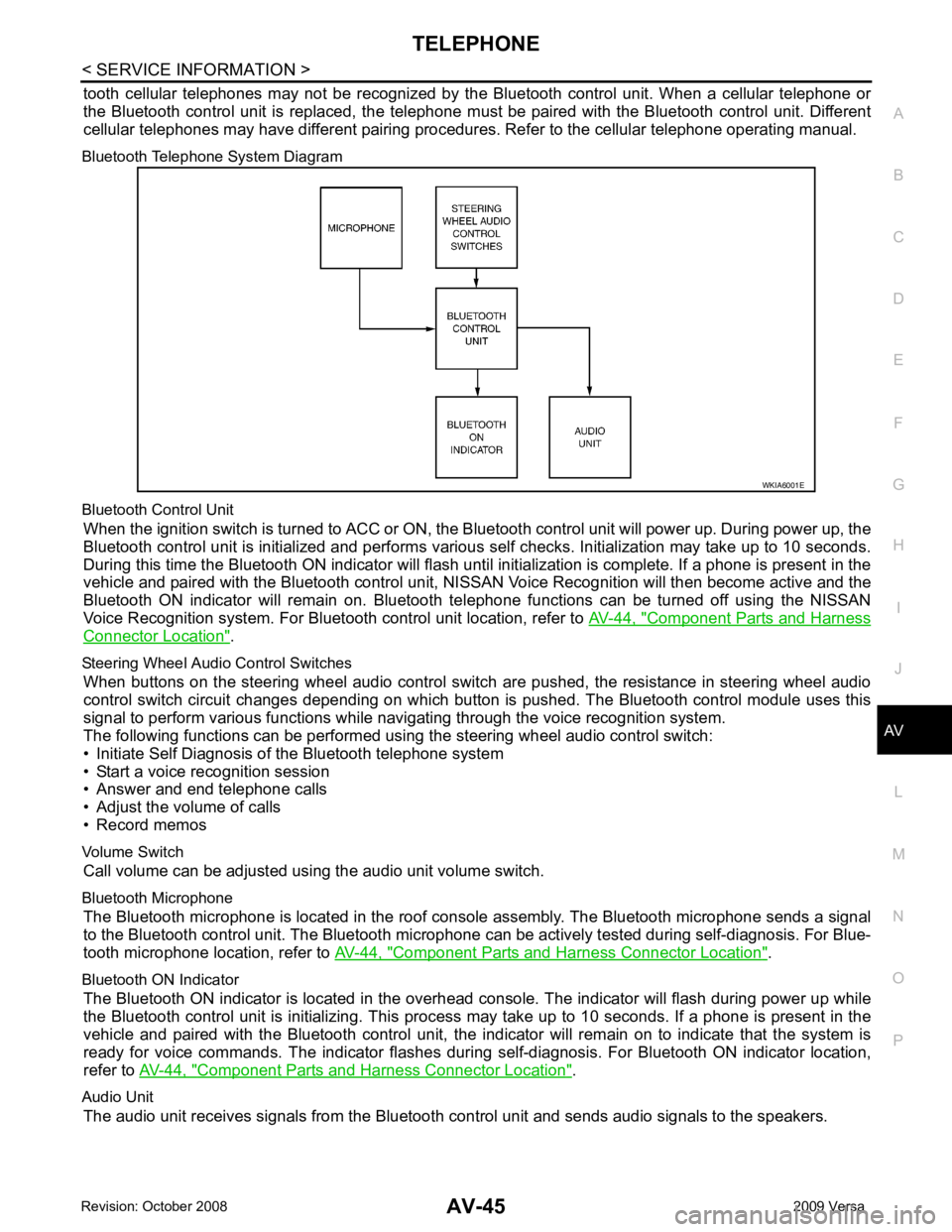
Bluetooth Telephone System Diagram
Bluetooth Control Unit When the ignition switch is turned to ACC or ON, the Bluetooth control unit will power up. During power up, the
Bluetooth control unit is initialized and performs various self checks. Initialization may take up to 10 seconds.
During this time the Bluetooth ON indicator will flash until initialization is complete. If a phone is present in the
vehicle and paired with the Bluetooth control unit, NIS SAN Voice Recognition will then become active and the
Bluetooth ON indicator will remain on. Bluetooth te lephone functions can be turned off using the NISSAN
Voice Recognition system. For Bluetooth control unit location, refer to AV-44, " Component Parts and Harness
Connector Location " .
Steering Wheel Audio Control Switches When buttons on the steering wheel audio control switch are pushed, the resistance in steering wheel audio
control switch circuit changes depending on which button is pushed. The Bluetooth control module uses this
signal to perform various functions while navigating through the voice recognition system.
The following functions can be performed usi ng the steering wheel audio control switch:
• Initiate Self Diagnosis of the Bluetooth telephone system
• Start a voice recognition session
• Answer and end telephone calls
• Adjust the volume of calls
• Record memos
Volume Switch Call volume can be adjusted using the audio unit volume switch.
Bluetooth Microphone The Bluetooth microphone is located in the roof c onsole assembly. The Bluetooth microphone sends a signal
to the Bluetooth control unit. The Bluetooth microphone can be actively tested during self-diagnosis. For Blue-
tooth microphone location, refer to AV-44, " Component Parts and Harness Connector Location " .
Bluetooth ON Indicator The Bluetooth ON indicator is located in the overhead console. The indicator will flash during power up while
the Bluetooth control unit is initializing. This process may take up to 10 seconds. If a phone is present in the
vehicle and paired with the Bluetooth control unit, the indi cator will remain on to indicate that the system is
ready for voice commands. The indicator flashes duri ng self-diagnosis. For Bluetooth ON indicator location,
refer to AV-44, " Component Parts and Harness Connector Location " .
Audio Unit The audio unit receives signals from the Bluetooth control unit and sends audio signals to the speakers.
Page 433 of 4331
AV
N
O P
Bluetooth Control Unit
Self-Diagnosis Function INFOID:0000000004306987
The Bluetooth control unit has two diagnostic checks. The first diagnostic check is performed automatically
every ignition cycle during control unit initialization. The second diagnostic check is performed by the techni-
cian using the steering wheel audio control switches prior to trouble diagnosis.
BLUETOOTH CONTROL UNIT INITIALIZATION CHECKS
• Internal control unit failure
• Bluetooth antenna connection open or shorted
• Steering wheel audio control swit ches (SEND/END) stuck closed
• Vehicle speed pulse count
• Bluetooth Microphone connection test (with playback to operator)
• Bluetooth inquiry check
SELF-DIAGNOSIS MODE 15 (G) Ground
Bluetooth
ON indicator
LED Output – Bluetooth control
unit initialized
and paired with
phone Battery voltage
Bluetooth ON indica-
tor inoperative.
17 (GR) Ground Audio unit
switch 1 OutputACC/
ON Press Phone/End
switch 0V
Steering wheel audio
controls do not func-
tion.
Press SEEK UP
switch 0.75V
Press VOL UP
switch 2V
Except for above 5V
18 (P) Ground Audio unit
switch 2 OutputACC/
ON Press Phone/
Send switch 0V
Steering wheel audio
controls do not func-
tion.
Press SEEK
DOWN switch 0.75V
Press VOL
DOWN switch 2V
Except for above 5V
19 (B) Ground Audio unit
switch
ground Output – – – Steering wheel audio
controls do not func-
tion.
20 (B) – Cont-1 – – – – –
21 (B) – Cont-2 – – – – –
23 (B) – Cont-4 – – – – –
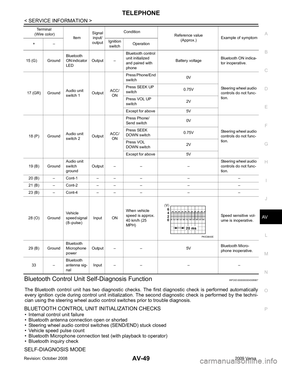
28 (O) Ground Vehicle
speed signal
(8–pulse) Input ON When vehicle
speed is approx.
40 km/h (25
MPH) Speed sensitive vol-
ume is inoperative.
29 (B) Ground Bluetooth
Microphone
power Output – – 5V
Bluetooth Micro-
phone inoperative.
33 – Bluetooth
antenna sig-
nal Input – – – –
Terminal
(Wire color) ItemSignal
input/
output Condition
Reference value
(Approx.) Example of symptom
+ – Ignition
switch Operation
Page 434 of 4331
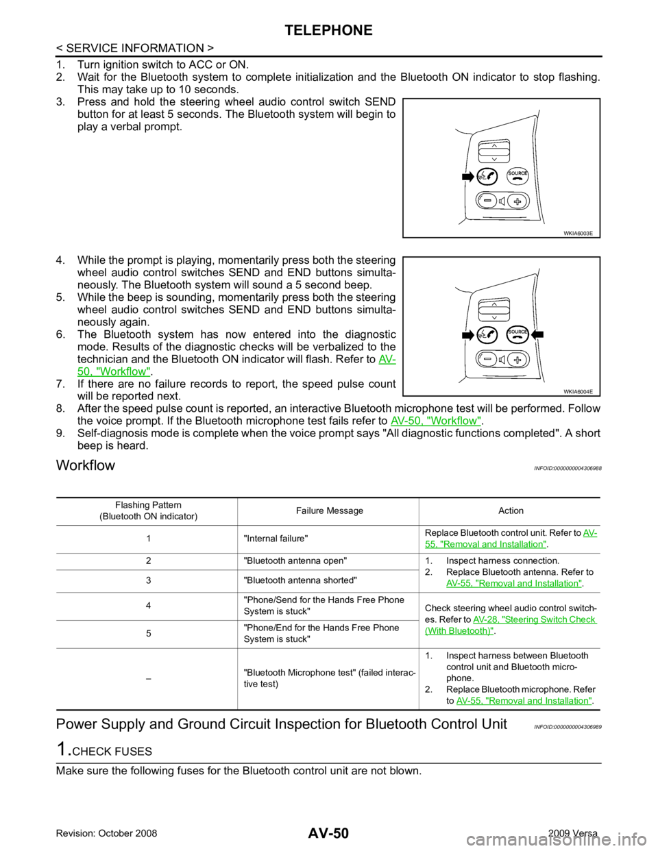
50, " Workflow " .
7. If there are no failure records to report, the speed pulse count will be reported next.
8. After the speed pulse count is reported, an intera ctive Bluetooth microphone test will be performed. Follow
the voice prompt. If the Bluetooth microphone test fails refer to AV-50, " Workflow " .
9. Self-diagnosis mode is complete when the voice prom pt says "All diagnostic functions completed". A short
beep is heard.
Workflow INFOID:0000000004306988
Power Supply and Ground Circuit Ins pection for Bluetooth Control Unit INFOID:0000000004306989 WKIA6004E
55, " Removal and Installation " .
2 "Bluetooth antenna open" 1. Inspect harness connection. 2. Replace Bluetooth antenna. Refer to AV-55, " Removal and Installation " .
3 "Bluetooth antenna shorted"
4 "Phone/Send for the Hands Free Phone
System is stuck" Check steering wheel audio control switch-
es. Refer to AV-28, " Steering Switch Check
(With Bluetooth) " .
5 "Phone/End for the Hands Free Phone
System is stuck"
– "Bluetooth Microphone test" (failed interac-
tive test) 1. Inspect harness between Bluetooth
control unit and Bluetooth micro-
phone.
2. Replace Bluetooth microphone. Refer to AV-55, " Removal and Installation " .
Page 436 of 4331
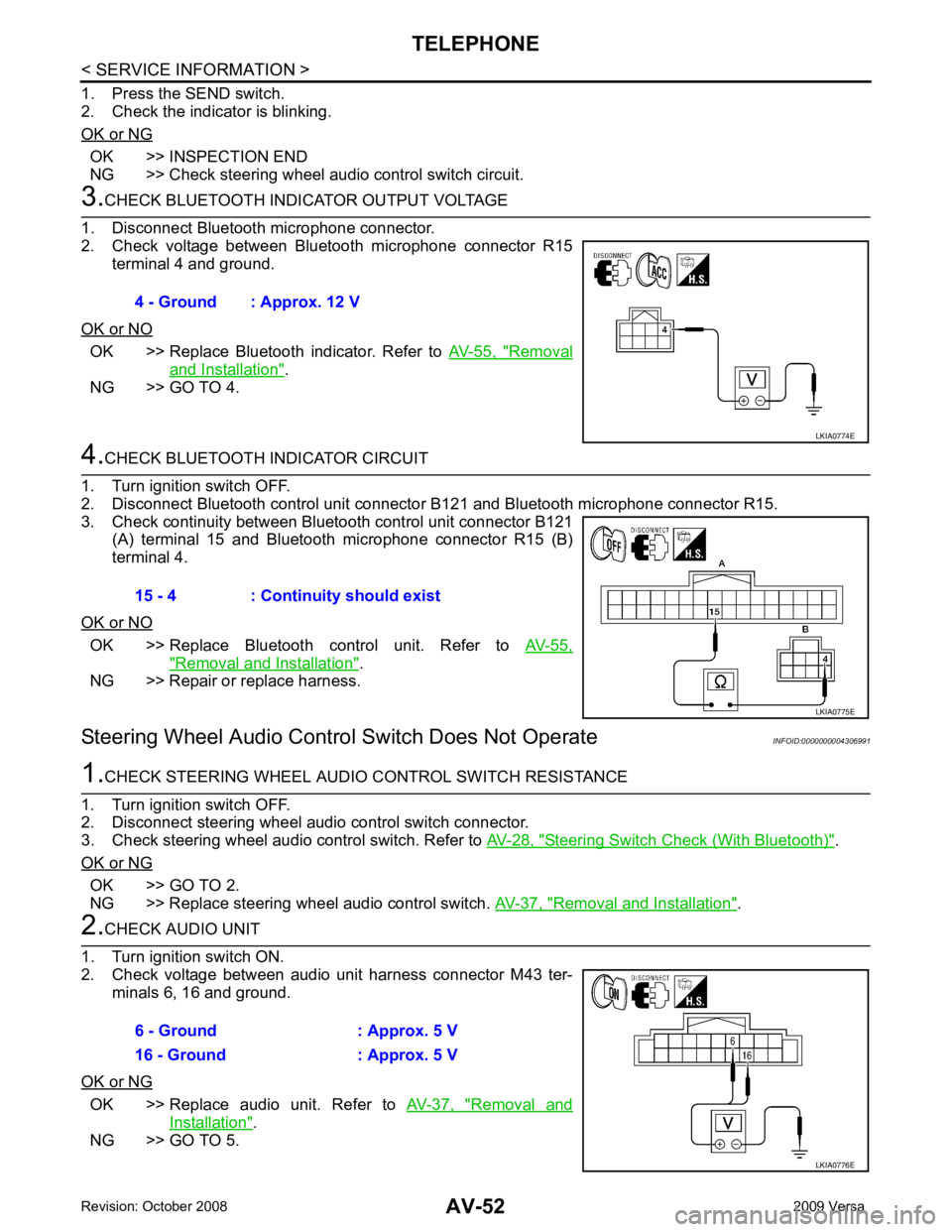
OK >> INSPECTION END
NG >> Check steering wheel audio control switch circuit. OK >> Replace Bluetooth indicator. Refer to
AV-55, " Removal
and Installation " .
NG >> GO TO 4. OK >> Replace Bluetooth control unit. Refer to
AV-55," Removal and Installation " .
NG >> Repair or replace harness.
Steering Wheel Audio Control Switch Does Not Operate INFOID:0000000004306991 Steering Switch Check (With Bluetooth) " .
OK or NG OK >> GO TO 2.
NG >> Replace steering wheel audio control switch. AV-37, " Removal and Installation " .
OK >> Replace audio unit. Refer to
AV-37, " Removal and
Installation " .
NG >> GO TO 5. 4 - Ground : Approx. 12 V
Page 437 of 4331
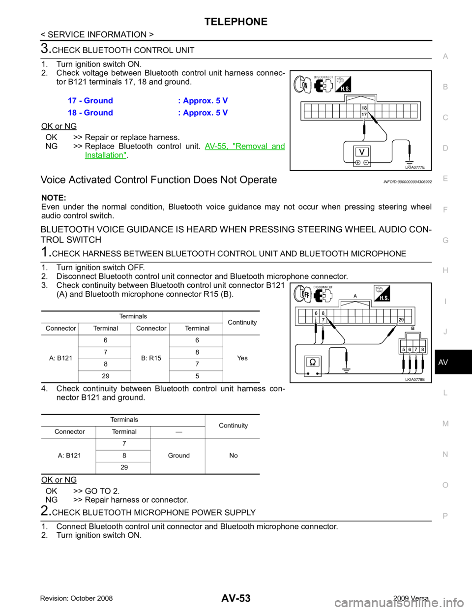
AV
N
O P OK >> Repair or replace harness.
NG >> Replace Bluetooth control unit. AV-55, " Removal and
Installation " .
Voice Activated Control F unction Does Not Operate INFOID:0000000004306992
NOTE:
Even under the normal condition, Bluetooth voice guidance may not occur when pressing steering wheel
audio control switch.
BLUETOOTH VOICE GUIDANCE IS HEARD WHEN PRESSING STEERING WHEEL AUDIO CON-
TROL SWITCH OK >> GO TO 2.
NG >> Repair harness or connector.
Page 438 of 4331
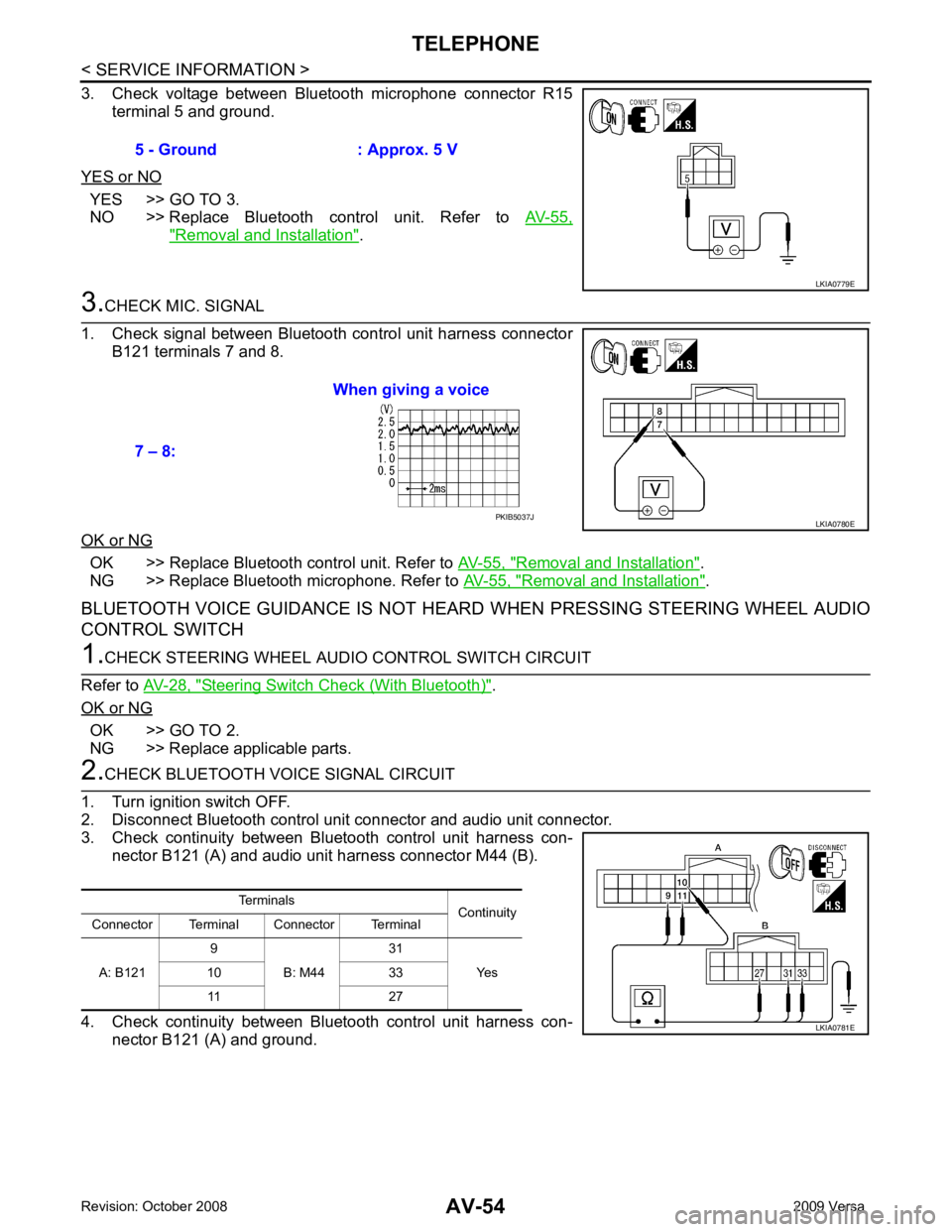
YES >> GO TO 3.
NO >> Replace Bluetooth control unit. Refer to AV-55," Removal and Installation " .
OK >> Replace Bluetooth control unit. Refer to
AV-55, " Removal and Installation " .
NG >> Replace Bluetooth microphone. Refer to AV-55, " Removal and Installation " .
BLUETOOTH VOICE GUIDANCE IS NOT HEARD WHEN PRESSING STEERING WHEEL AUDIO
CONTROL SWITCH Steering Switch Check (With Bluetooth) " .
OK or NG OK >> GO TO 2.
NG >> Replace applicable parts. PKIB5037J
Terminals Continuity
Connector Terminal Connector Terminal
A: B121 9
B: M44 31
Yes
10 33
11 27
Page 462 of 4331

BL
N
O P
CONTENTS
BODY, LOCK & SECURITY SYSTEM
SERVICE INFORMATION .. ..........................4
PRECAUTIONS .............................................. .....4
Precaution for Supplemental Restraint System
(SRS) "AIR BAG" and "SEAT BELT PRE-TEN-
SIONER" ............................................................. ......
4
Precaution Necessary fo r Steering Wheel Rota-
tion After Battery Disconnect ............................... ......
4
Precaution for Procedure without Cowl Top Cover ......5
Precaution for Work ............................................ ......5
PREPARATION .............................................. .....6
Special Service Tool ........................................... ......6
Commercial Service Tool .................................... ......6
SQUEAK AND RATTLE TROUBLE DIAG-
NOSES ........................ ........................................7
Work Flow ........................................................... ......7
Generic Squeak and Rattle Troubleshooting ...... ......9
Diagnostic Worksheet ......................................... ....11
HOOD ............................................................. ....13
Fitting Adjustment ............................................... ....13
Removal and Installation .........................................14
Removal and Installation of Hood Lock Control .. ....15
Hood Lock Control Inspec tion .................................17
RADIATOR CORE SUPPORT ....................... ....19
Removal and Installation .........................................19
FRONT FENDER ............................................ ....21
Removal and Installation .........................................21
POWER DOOR LOCK SYSTEM .................... ....22
Component Parts and Harness Connector Loca-
tion ...................................................................... ....
22
System Description ............................................. ....23
CAN Communication System Description ........... ....25
Schematic ........................................................... ....26
Wiring Diagram - D/LOCK - ................................. ....27
Schematic ........................................................... ....31
Wiring Diagram - D/LOCK - ................................. ....32 Terminal and Reference
Value for BCM ..................37
Work Flow ............................................................ ....41
CONSULT-III Function (B CM) .................................41
Trouble Diagnosis Symptom Chart ...................... ....43
BCM Power Supply and Ground Circuit Inspection ....43
Door Switch Check (Hatchback) .......................... ....44
Door Switch Check (Sedan) ................................ ....47
Key Switch (Insert) Check ................................... ....48
Door Lock and Unlock Switch Check .................. ....49
Front Door Lock Assembly LH (Actuator) Check .....52
Door Lock Actuator Check (Front RH and Rear
LH/RH) ................................................................. ....
53
Front Door Key Cylinder S witch LH Check ..............54
Passenger Select Unlock Relay Circuit Inspection
(With Intelligent Key) ........................................... ....
55
REMOTE KEYLESS ENTRY SYSTEM ............. 58
Component Parts and Harness Connector Loca-
tion ....................................................................... ....
58
System Description .............................................. ....58
CAN Communication System Description ........... ....60
Schematic ............................................................ ....61
Wiring Diagram - KEYLES - ................................ ....62
Terminal and Reference Value for BCM ..................65
How to Perform Trouble Diagnosis ...................... ....69
Preliminary Check ............................................... ....69
CONSULT-III Function (B CM) .................................69
Work Flow ............................................................ ....71
Trouble Diagnosis Symptom Chart ...................... ....71
Keyfob Battery and Function Check .................... ....72
ACC Switch Check .............................................. ....74
Door Switch Check (Hatchback) .......................... ....74
Door Switch Check (Sedan) ................................ ....76
Key Switch (Insert) Check ................................... ....78
Hazard Function Check ....................................... ....78
Horn Function Check ........................................... ....79
Interior Lamp and Ignition Keyhole Illumination
Function Check .................................................... ....
79
Remote Keyless Entry Rece iver Check ...................80
Keyfob Function (Lock) Check ............................ ....82