Page 4272 of 4331

ROAD WHEEL TIRE ASSEMBLY
WT-7
< SERVICE INFORMATION >
C
D
F
G H
I
J
K L
M A
B WT
N
O P
ROAD WHEEL TIRE ASSEMBLY
Balancing Wheels INFOID:0000000004307317
Adjust wheel balance using road wheel center.
CAUTION:
• Be careful not to scratch th e road wheel during removal.
• Use clip-on type wheel balance weights only.
Wheel balance (Maximum allowable unbalance):
Rotation INFOID:0000000004307318
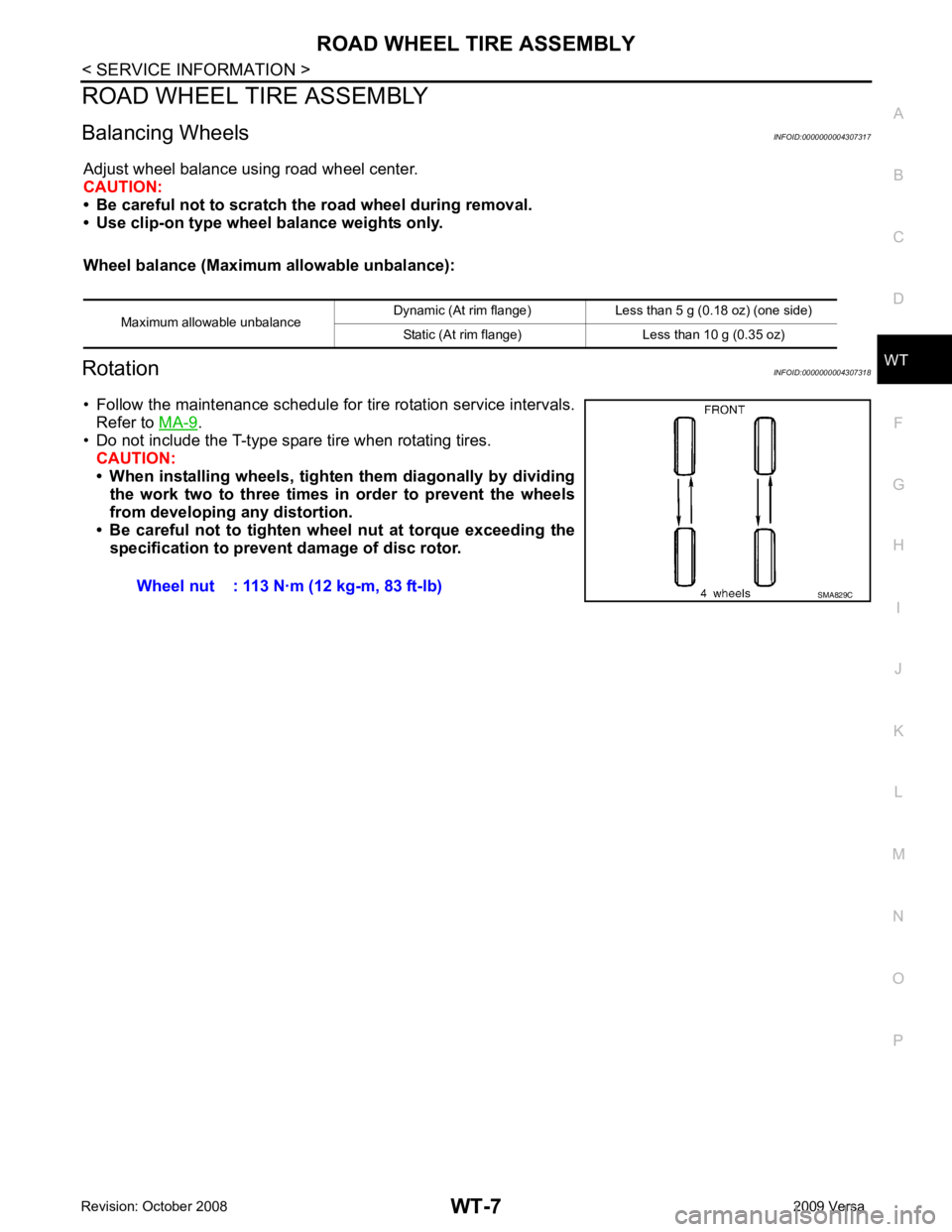
• Follow the maintenance schedule for tire rotation service intervals. Refer to MA-9 .
• Do not include the T-type spare tire when rotating tires. CAUTION:
• When installing wheels, tighte n them diagonally by dividing
the work two to three times in order to prevent the wheels
from developing any distortion.
• Be careful not to tighten wh eel nut at torque exceeding the
specification to prevent damage of disc rotor.
Maximum allowable unbalance
Dynamic (At rim flange) Less than 5 g (0.18 oz) (one side)
Static (At rim flange) Less than 10 g (0.35 oz) Wheel nut : 113 N·m (12 kg-m, 83 ft-lb)
SMA829C
Page 4274 of 4331

WT
N
O P
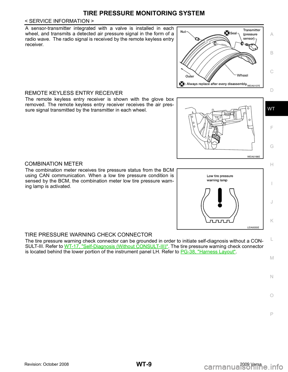
A sensor-transmitter integrated with a valve is installed in each
wheel, and transmits a detected air pressure signal in the form of a
radio wave. The radio signal is received by the remote keyless entry
receiver.
REMOTE KEYLESS ENTRY RECEIVER The remote keyless entry receiver is shown with the glove box
removed. The remote keyless entry receiver receives the air pres-
sure signal transmitted by the transmitter in each wheel.
COMBINATION METER The combination meter receives tire pressure status from the BCM
using CAN communication. When a low tire pressure condition is
sensed by the BCM, the combination meter low tire pressure warn-
ing lamp is activated.
TIRE PRESSURE WARNING CHECK CONNECTOR The tire pressure warning check connector can be grounded in order to initiate self-diagnosis without a CON-
SULT-III. Refer to WT-17, " Self-Diagnosis (Without CONSULT-III) " . The tire pressure warning check connector
is located behind the lower portion of the instrument panel LH. Refer to PG-38, " Harness Layout " . WEIA0186E
LEIA0055E
Page 4281 of 4331

OK >> GO TO 4.
NG >> Repair or replace damaged parts. OK >> Carry out self-diagnosis.
NG >> Replace battery in transmitter activation tool.
Self-Diagnosis (With CONSULT-III) INFOID:0000000004307329
DESCRIPTION
During driving, the tire pressure monitoring system receives the signal transmitted from the transmitter
installed in each wheel, and turns on the low tire pressure warning lamp when the tire pressure becomes low.
The control unit (BCM) for this system has pressure judgement and self-diagnosis functions.
FUNCTION
When the tire pressure monitoring syst em detects low inflation pressure or an internal malfunction, the low tire
pressure warning lamp in the combination meter comes on. The malfunction location is indicated by the low
tire pressure warning lamp flashing and the buzzer sounding.
CONSULT-III Application to Tire Pressure Monitoring System
× : Applicable
– : Not applicable
Self-Diagnostic Results Mode ITEM SELF-DIAGNOSTIC RESULTS DATA MONITOR
Front - Left transmitter × ×
Front - Right transmitter × ×
Rear - Left transmitter × ×
Rear - Right transmitter × ×
Warning lamp — ×
Vehicle speed × ×
Buzzer (in combination meter) — ×
CAN Communication × × 8, " System Description " .
Page 4290 of 4331

WT
N
O P
REMOVAL AND INSTALLATION
Transmitter (Pressure Sensor) INFOID:0000000004307341
REMOVAL 1. Remove wheel and tire using power tool.
2. Deflate tire. Unscrew transmitter retaining nut and allow transmitter to fall into tire.
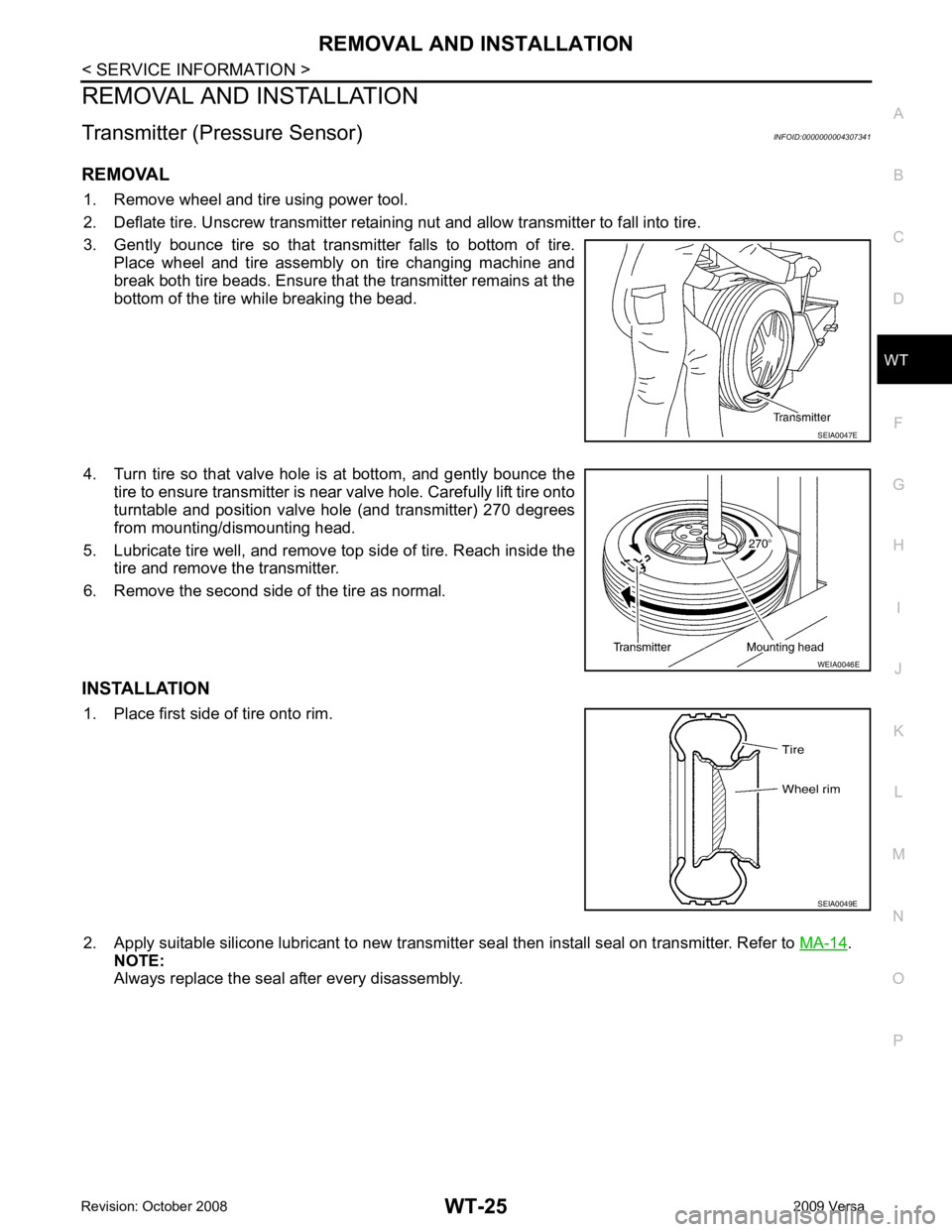
3. Gently bounce tire so that transmitter falls to bottom of tire. Place wheel and tire assembly on tire changing machine and
break both tire beads. Ensure that the transmitter remains at the
bottom of the tire while breaking the bead.
4. Turn tire so that valve hole is at bottom, and gently bounce the tire to ensure transmitter is near valve hole. Carefully lift tire onto
turntable and position valve hole (and transmitter) 270 degrees
from mounting/dismounting head.
5. Lubricate tire well, and remove top side of tire. Reach inside the tire and remove the transmitter.
6. Remove the second side of the tire as normal.
INSTALLATION 1. Place first side of tire onto rim.
2. Apply suitable silicone lubricant to new transmitter seal then install seal on transmitter. Refer to MA-14 .
NOTE:
Always replace the seal after every disassembly.
Page 4291 of 4331
WT-26< SERVICE INFORMATION >
REMOVAL AND INSTALLATION
3. Mount transmitter on rim and tighten nut. NOTE:
Make sure no burrs exist in the valve stem hole of the wheel.
4. Place wheel on turntable of tire machine. Ensure that transmitter is 270 degrees from mounting/dismounting head.
NOTE:
Do not touch transmitter with mounting head.
5. Lubricate tire well, and install second side of tire as normal. Ensure that tire does not rotate relative to rim.
6. Inflate tire and balance the wheel and tire assembly. Refer to WT-7, " Balancing Wheels " .
7. Install wheel and tire assembly in appropriate wheel position on vehicle. Refer to WT-7, " Rotation " .
NOTE:
If replacing the transmitter, then transmitter wake up operation
must be performed. Refer to WT-13, " Transmitter Wake Up Operation " .
Transmitter nut : 7.7 N·m (0.79 kg-m, 68 in-lb) WEIA0137E
WEIA0046E
Page 4292 of 4331
WT
N
O P
SERVICE DATA AND SPECIFICATIONS (SDS)
Road Wheel INFOID:0000000004307342
Tire INFOID:0000000004307343
Unit: kPa (kg/cm 2
, psi)
Standard item
Allowable
Aluminum Steel
Maximum radial runout limit Lateral deflection Less than 0.3 mm (0.012 in) Less than 0.5 mm (0.020 in)
Radial deflection Less than 0.3 mm (0.012 in) Less than 0.8 mm (0.031 in)
Maximum allowable unbalance Dynamic
(At rim flange) Less than 5 g (0.18 oz) (one side)
Static
(At rim flange) Less than 10 g (0.35 oz)Tire size/speed rating
Cold tire pressure
Conventional tire Spare tire
Front wheel Rear wheel
P185/65R14 230 (2.3, 33) 230 (2.3, 33) —
P185/65R15 230 (2.3, 33) 230 (2.3, 33) —
T125/70D15 — — 420 (4.2, 60)