2009 NISSAN LATIO wheel
[x] Cancel search: wheelPage 738 of 4331
BL
N
O P
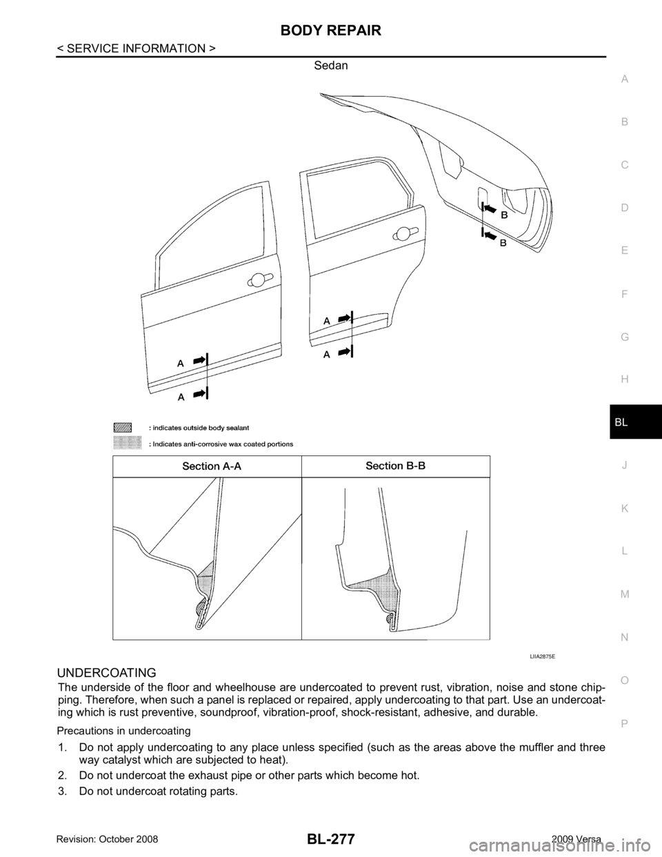
Sedan
UNDERCOATING The underside of the floor and wheelhouse are undercoated to prevent rust, vibration, noise and stone chip-
ping. Therefore, when such a panel is replaced or re paired, apply undercoating to that part. Use an undercoat-
ing which is rust preventive, soundproof, vibr ation-proof, shock-resistant, adhesive, and durable.
Precautions in undercoating 1. Do not apply undercoating to any place unless specif ied (such as the areas above the muffler and three
way catalyst which are subjected to heat).
2. Do not undercoat the exhaust pipe or other parts which become hot.
3. Do not undercoat rotating parts.
Page 770 of 4331
BL
N
O P
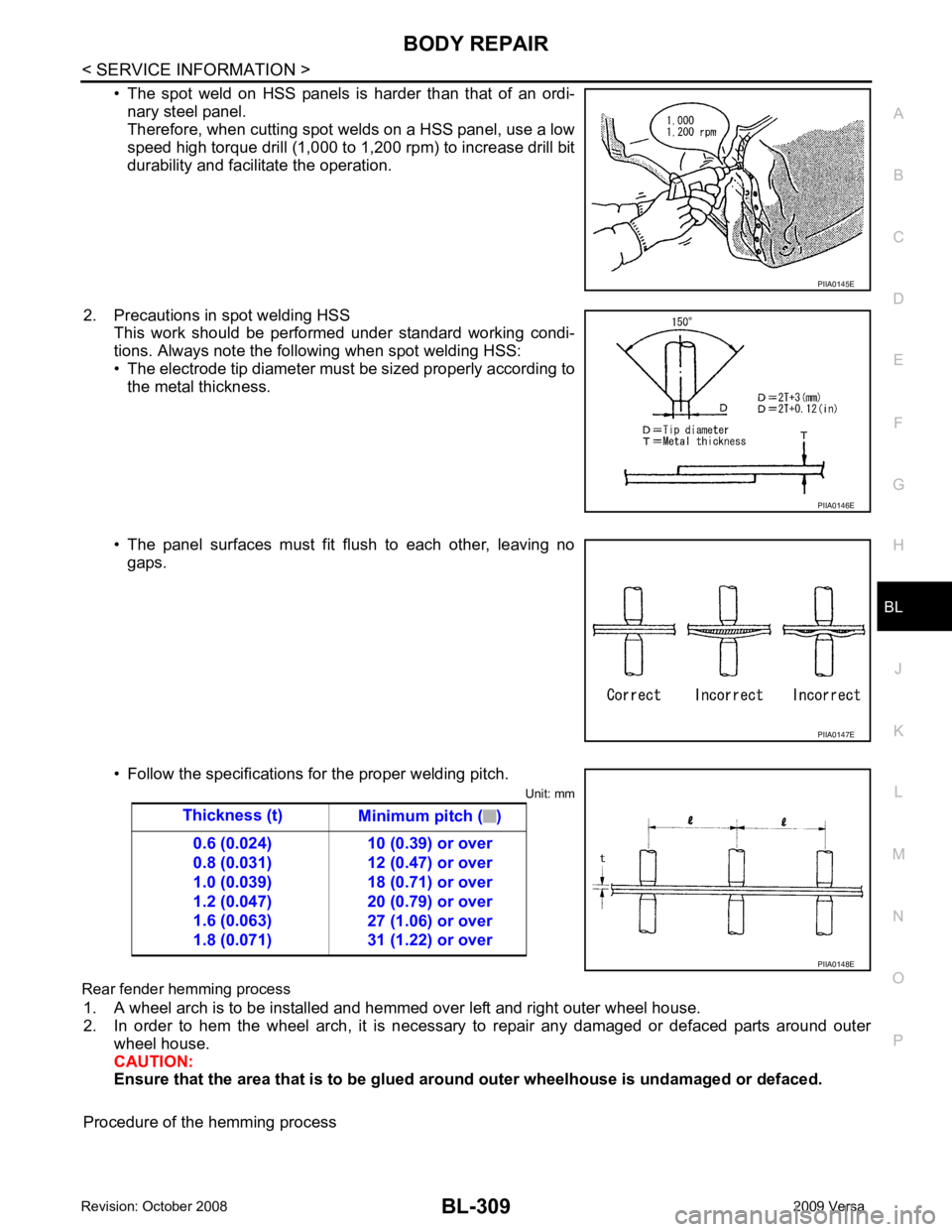
• The spot weld on HSS panels is harder than that of an ordi-
nary steel panel.
Therefore, when cutting spot welds on a HSS panel, use a low
speed high torque drill (1,000 to 1,200 rpm) to increase drill bit
durability and facilitate the operation.
2. Precautions in spot welding HSS This work should be performed under standard working condi-
tions. Always note the following when spot welding HSS:
• The electrode tip diameter must be sized properly according to the metal thickness.
• The panel surfaces must fit flush to each other, leaving no gaps.
• Follow the specifications for the proper welding pitch. Unit: mm
Rear fender hemming process 1. A wheel arch is to be installed and hemmed over left and right outer wheel house.
2. In order to hem the wheel arch, it is necessary to repair any damaged or defaced parts around outer
wheel house.
CAUTION:
Ensure that the area that is to be glued around outer wheelhouse is undamaged or defaced.
Procedure of the hemming process PIIA0146E
PIIA0147E
Page 772 of 4331
BL
N
O P
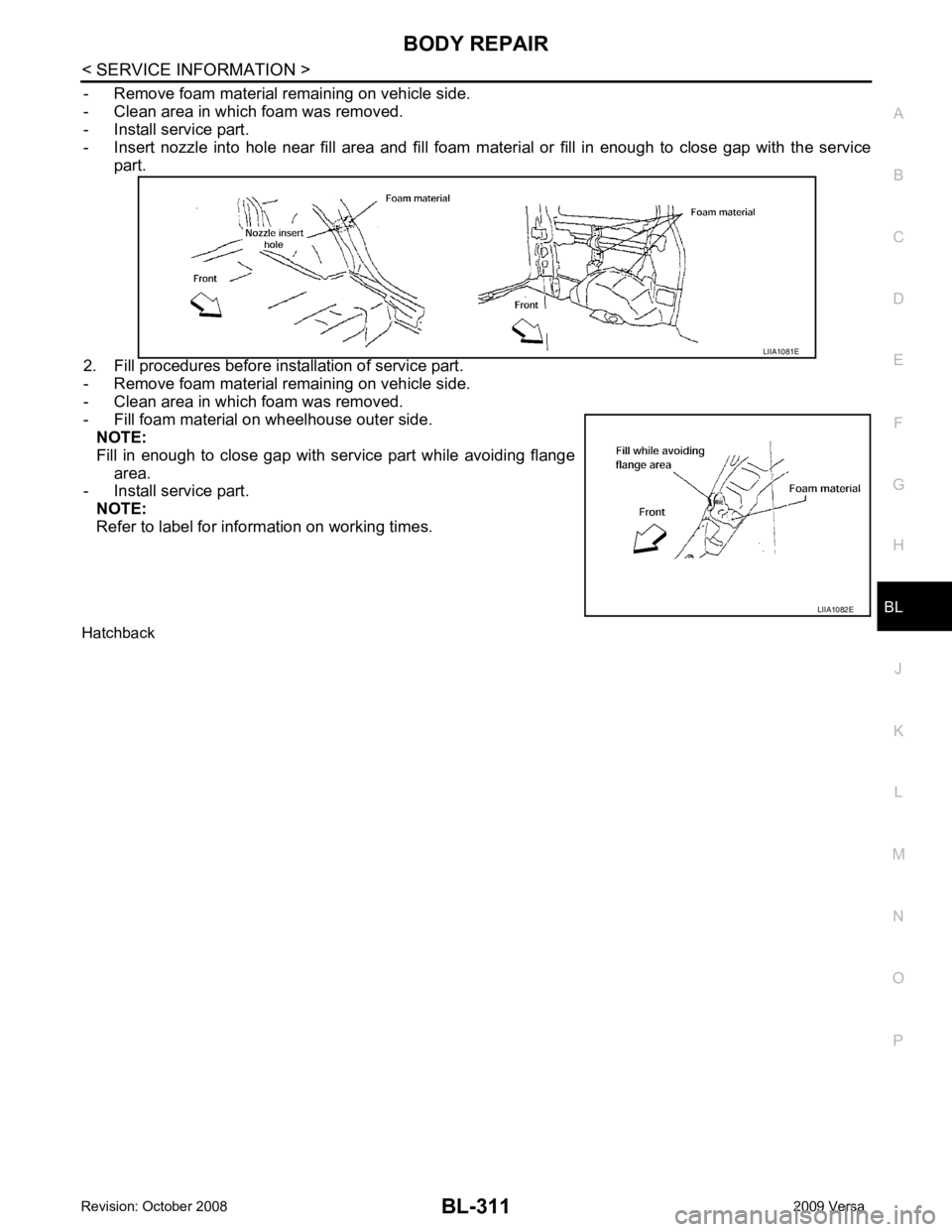
- Remove foam material remaining on vehicle side.
- Clean area in which foam was removed.
- Install service part.
- Insert nozzle into hole near fill area and fill foam material or fill in enough to close gap with the service
part.
2. Fill procedures before installation of service part.
- Remove foam material remaining on vehicle side.
- Clean area in which foam was removed.
- Fill foam material on wheelhouse outer side. NOTE:
Fill in enough to close gap with service part while avoiding flange area.
- Install service part.
NOTE:
Refer to label for information on working times.
Hatchback LIIA1082E
Page 801 of 4331

BR
N
O P
CONTENTS
BRAKE SYSTEM
SERVICE INFORMATION .. ..........................2
PRECAUTIONS .............................................. .....2
Precaution for Supplemental Restraint System
(SRS) "AIR BAG" and "SEAT BELT PRE-TEN-
SIONER" ............................................................. ......
2
Precaution Necessary fo r Steering Wheel Rota-
tion After Battery Disconnect ............................... ......
2
Precaution for Brake System .............................. ......3
PREPARATION .............................................. .....4
Special Service Tool ........................................... ......4
Commercial Service Tool .................................... ......4
NOISE, VIBRATION AND HARSHNESS
(NVH) TROUBLESHOOTING ........................ .....5
NVH Troubleshooting Chart ................................ ......5
BRAKE PEDAL .............................................. .....6
Inspection and Adjustment .................................. ......6
Removal and Installation ...........................................7
BRAKE FLUID .....................................................9
On Board Inspection ........................................... ......9
Drain and Refill .................................................... ......9
Bleeding Brake System ....................................... ......9
BRAKE TUBE AND HOSE ............................ ....11
Hydraulic Circuit .................................................. ....11
Front Brake Tube and Hose ................................ ....12
Rear Brake Tube and Hose ................................ ....12
Inspection After Installation ................................. ....13
DUAL PROPORTIONING VALVE ................. ....14
Removal and Installation .........................................14
Inspection ............................................................ ....14
BRAKE MASTER CY LINDER ........................ ....15
On-Board Inspection ........................................... ....15 Removal and Installation .....................................
....15
Disassembly and Assembly ................................. ....16
BRAKE BOOSTER ........................................... 20
On Board Inspection ............................................ ....20
Removal and Installation ..................................... ....21
VACUUM LINES ............................................... 23
Component .......................................................... ....23
Removal and Installation ..................................... ....23
Inspection ............................................................ ....23
FRONT DISC BRAKE ....................................... 25
On Board Inspection ............................................ ....25
Component .......................................................... ....25
Removal and Installation of Brake Pad ...................26
Removal and Installation of Brake Caliper Assem-
bly ........................................................................ ....
28
Disassembly and Assembly of Brake Caliper As-
sembly ................................................................. ....
29
Brake Burnishing Procedure ................................ ....32
REAR DRUM B RAKE ....................................... 33
Component .......................................................... ....33
Removal and Installation of Drum Brake Assembly ....34
Removal and Installation of Wheel Cylinder ........ ....37
Disassembly and Assembly of Wheel Cylinder ... ....37
SERVICE DATA AND SPECIFICATIONS
(SDS) ................................................................. 38
General Specification .......................................... ....38
Brake Pedal ......................................................... ....39
Check Valve ........................................................ ....39
Brake Booster ...................................................... ....40
Front Disc Brake .................................................. ....40
Rear Drum Brake ................................................. ....40
Page 803 of 4331
BR
N
O P
5. When the repair work is completed, return the ignition switch to the
″LOCK ″ position before connecting
the battery cables. (At this time, the steering lock mechanism will engage.)
6. Perform a self-diagnosis check of al l control units using CONSULT-III.
Precaution for Brake System INFOID:0000000004305887
• Refill using recommended brake fluid. Refer to MA-14 .
• Never reuse drained brake fluid.
• Be careful not to splash brake fluid on painted surfac e of body. If brake fluid is splashed on painted surfaces
of body immediately wipe it off with cloth and then wash it away with water.
• To clean or wash all parts of master cylinder, disc brake caliper and wheel cylinder, use new brake fluid.
• Never use mineral oils such as gasoline or kerosene. They will ruin rubber parts of the hydraulic system.
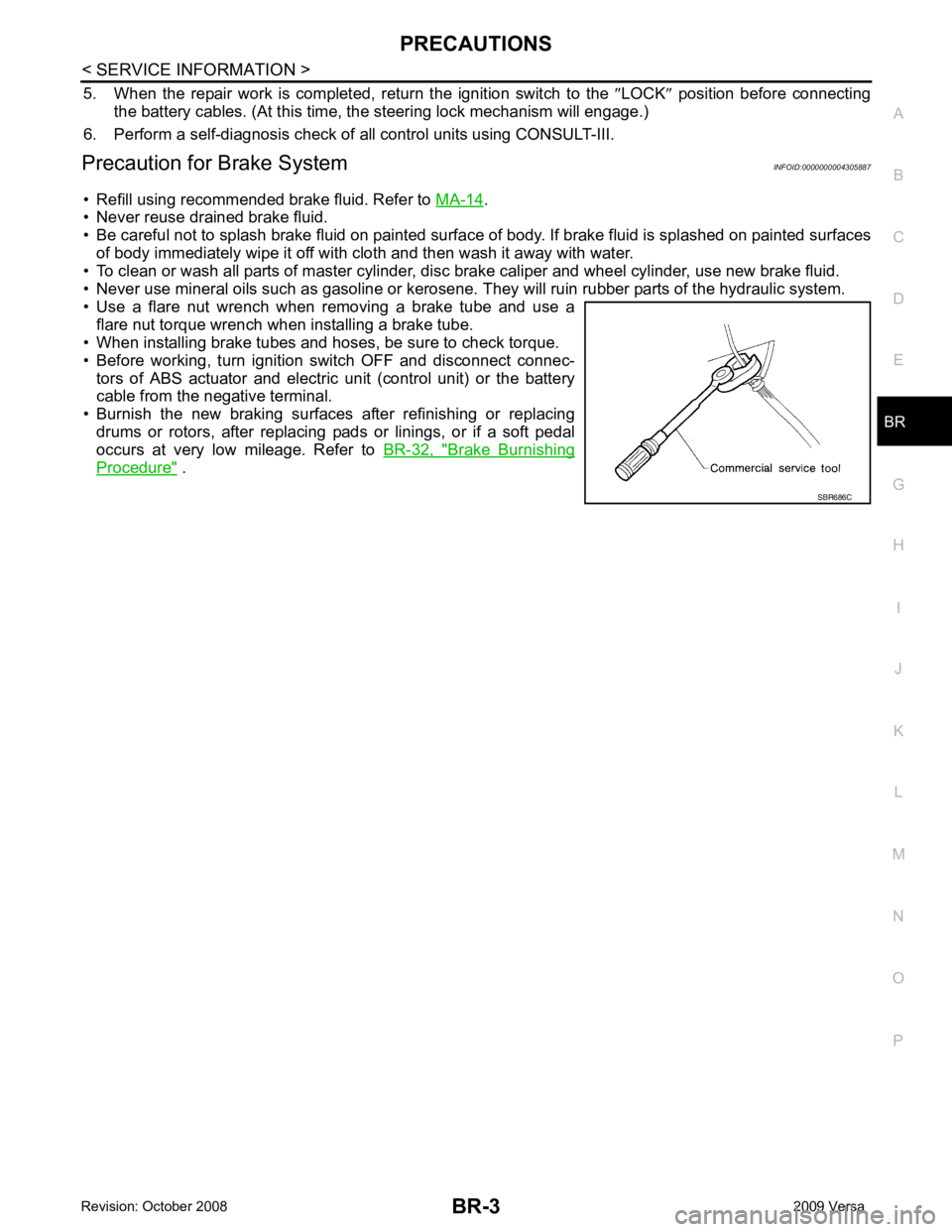
• Use a flare nut wrench when removing a brake tube and use a flare nut torque wrench when installing a brake tube.
• When installing brake tubes and hoses, be sure to check torque.
• Before working, turn igniti on switch OFF and disconnect connec-
tors of ABS actuator and electric unit (control unit) or the battery
cable from the negative terminal.
• Burnish the new braking surfaces after refinishing or replacing drums or rotors, after replacing p ads or linings, or if a soft pedal
occurs at very low mileage. Refer to BR-32, " Brake Burnishing
Procedure " .
Page 805 of 4331
BR
N
O P
NOISE, VIBRATION AND HARSHN
ESS (NVH) TROUBLESHOOTING
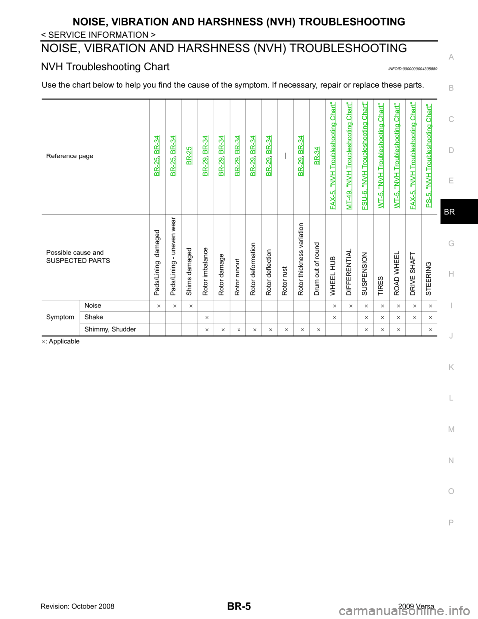
NVH Troubleshooting Chart INFOID:0000000004305889
Use the chart below to help you find t he cause of the symptom. If necessary, repair or replace these parts.
× : ApplicableReference pageBR-25
,
BR-34
BR-25
, BR-34BR-25
BR-29
, BR-34
BR-29
, BR-34
BR-29
, BR-34
BR-29
, BR-34
BR-29
, BR-34—
BR-29, BR-34BR-34
FAX-5, "
NVH Troubleshooting Chart
"
MT-49, "
NVH Troubleshooting Chart
"
FSU-6, "
NVH Troubleshooting Chart
"
WT-5, "
NVH Troubleshooting Chart
"
WT-5, "
NVH Troubleshooting Chart
"
FAX-5, "
NVH Troubleshooting Chart
"
PS-5, "
NVH Troubleshooting Chart
" Possible cause and
SUSPECTED PARTS
Pads/Lining damaged
Pads/Lining - uneven wear
Shims damaged
Rotor imbalance
Rotor damage
Rotor runout
Rotor deformation
Rotor deflection
Rotor rust
Rotor thickness variation
Drum out of round
WHEEL HUB
DIFFERENTIAL
SUSPENSION
TIRES
ROAD WHEEL
DRIVE SHAFT
STEERING
Symptom Noise
× × × × × × × × × ×
Shake × × × × × × ×
Shimmy, Shudder × × × × × × × × × × × ×
Page 809 of 4331
BR
N
O P
BRAKE FLUID
On Board Inspection INFOID:0000000004305892
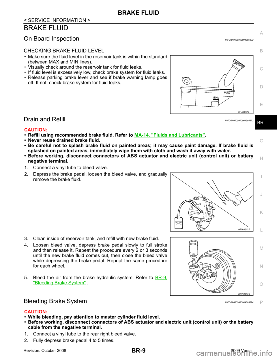
CHECKING BRAKE FLUID LEVEL • Make sure the fluid level in the reservoir tank is within the standard (between MAX and MIN lines).
• Visually check around the reservoir tank for fluid leaks.
• If fluid level is excessively low, check brake system for fluid leaks.
• Release parking brake lever and see if brake warning lamp goes
off. If not, check brake system for fluid leaks.
Drain and Refill INFOID:0000000004305893
CAUTION:
• Refill using recommended brake fluid. Refer to MA-14, " Fluids and Lubricants " .
• Never reuse drained brake fluid.
• Be careful not to splash brake fluid on painted areas; it may cause paint damage. If brake fluid is
splashed on painted areas, immediately wipe th em with cloth and wash it away with water.
• Before working, disconnect connect ors of ABS actuator and electric unit (control unit) or battery
negative terminal.
1. Connect a vinyl tube to bleed valve.
2. Depress the brake pedal, loosen the bleed valve, and gradually remove the brake fluid.
3. Clean inside of reservoir tank, and refill with new brake fluid.
4. Loosen bleed valve, depress brake pedal slowly to full stroke and then release it. Repeat the procedure every 2 or 3 seconds
until the new brake fluid comes out, then close the bleed valve
while depressing the brake pedal . Repeat the same procedure
for each wheel.
5. Bleed the air from the brake hydraulic system. Refer to BR-9," Bleeding Brake System " .
Bleeding Brake System INFOID:0000000004305894
CAUTION:
• While bleeding, pay attention to master cylinder fluid level.
• Before working, disconnect connectors of ABS actuator and electri c unit (control unit) or the battery
cable from the negative terminal.
1. Connect a vinyl tube to the rear right bleed valve.
2. Fully depress brake pedal 4 to 5 times.
Page 827 of 4331
BR
N
O P
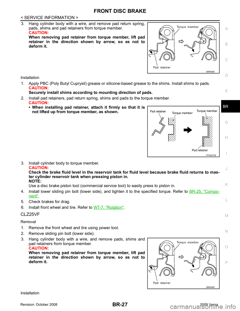
3. Hang cylinder body with a wire, and remove pad return spring,
pads, shims and pad retainers from torque member.
CAUTION:
When removing pad retainer from torque member, lift pad
retainer in the direction shown by arrow, so as not to
deform it.
Installation 1. Apply PBC (Poly Butyl Cuprysil) grease or silicone- based grease to the shims. Install shims to pads.
CAUTION:
Securely install shims according to mounting direction of pads.
2. Install pad retainers, pad return spring, shims and pads to the torque member. CAUTION:
• When installing pad retainer, at tach it firmly so that it is
not lifted up from torque member, as shown.
3. Install cylinder body to torque member. CAUTION:
Check the brake fluid level in the reservoir tank for fluid level because brake fluid returns to mas-
ter cylinder reservoir tank when pressing piston in.
NOTE:
Use a disc brake piston tool (commercial se rvice tool) to easily press to piston in.
4. Install lower sliding pin bolt (lower side), and tighten it to the specified torque. Refer to BR-25, " Compo-
nent " .
5. Check brakes for drag.
6. Install front wheel and tire. Refer to WT-7, " Rotation " .
CLZ25VF
Removal 1. Remove the front wheel and tire using power tool.
2. Remove sliding pin bolt (lower side).
3. Hang cylinder body with a wire, and remove pads, shims and pad retainers from torque member.
CAUTION:
When removing pad retainer from torque member, lift pad
retainer in the direction shown by arrow, so as not to
deform it.
Installation SBR556E