2009 NISSAN LATIO tire pressure
[x] Cancel search: tire pressurePage 688 of 4331

VEHICLE SECURITY (THEFT WARNING) SYSTEM
BL-227
< SERVICE INFORMATION >
C
D E
F
G H
J
K L
M A
B BL
N
O P
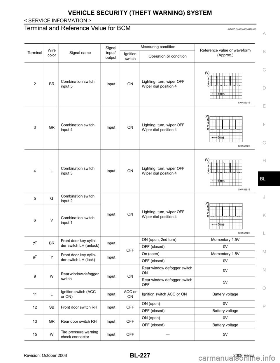
Terminal and Reference Value for BCM
INFOID:0000000004678913
Terminal Wire
color Signal name Signal
input/
output Measuring condition
Reference value or waveform
(Approx.)
Ignition
switch Operation or condition
2 BR Combination switch
input 5 Input ONLighting, turn, wiper OFF
Wiper dial position 4
3 GR Combination switch
input 4 Input ONLighting, turn, wiper OFF
Wiper dial position 4
4 L Combination switch
input 3 Input ONLighting, turn, wiper OFF
Wiper dial position 4
5 G Combination switch
input 2
Input ONLighting, turn, wiper OFF
Wiper dial position 4
6 V Combination switch
input 1
7 7
BRFront door key cylin-
der switch LH (unlock) Input
OFFON (open, 2nd turn) Momentary 1.5V
OFF (closed) 0V
8 7
YFront door key cylin-
der switch LH (lock) InputOn (open) Momentary 1.5V
OFF (closed) 0V
9 W Rear window defogger
switch Input ONRear window defogger switch
ON 0V
Rear window defogger switch
OFF 5V
11 L Ignition switch (ACC
or ON) InputACC or
ON Ignition switch ACC or ON Battery voltage
12 SB Front door switch RH Input OFF ON (open) 0V
OFF (closed) Battery voltage
13 GR Rear door switch RH Input OFF ON (open) 0V
OFF (closed) Battery voltage
15 W Tire pressure warning
check connector Input OFF — 5V SKIA5291E
SKIA5292E
SKIA5291E
SKIA5292E
Page 713 of 4331

BL-252< SERVICE INFORMATION >
NATS (NISSAN ANTI-THEFT SYSTEM)
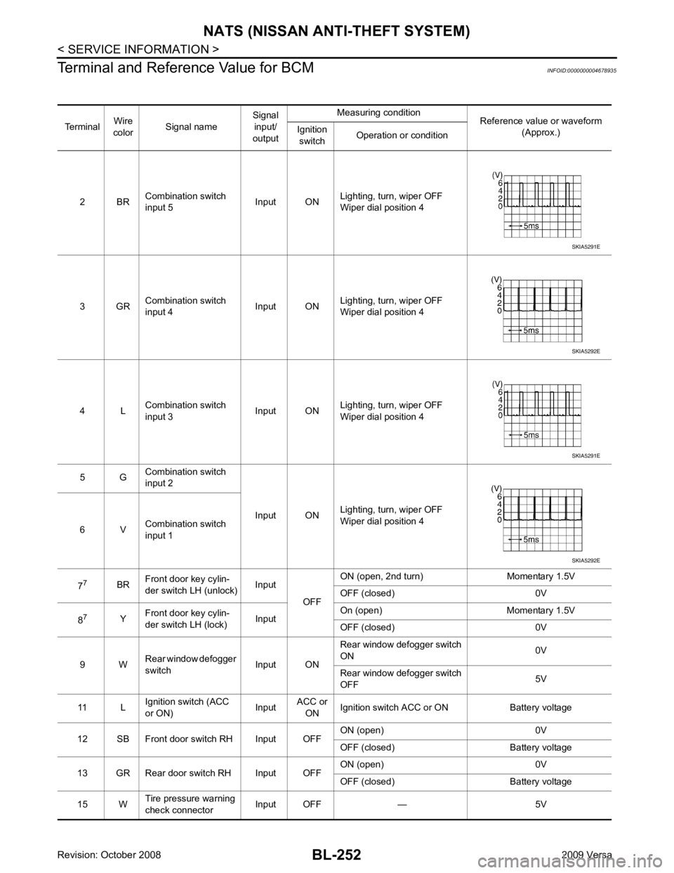
Terminal and Reference Value for BCM INFOID:0000000004678935
Terminal Wire
color Signal name Signal
input/
output Measuring condition
Reference value or waveform
(Approx.)
Ignition
switch Operation or condition
2 BR Combination switch
input 5 Input ONLighting, turn, wiper OFF
Wiper dial position 4
3 GR Combination switch
input 4 Input ONLighting, turn, wiper OFF
Wiper dial position 4
4 L Combination switch
input 3 Input ONLighting, turn, wiper OFF
Wiper dial position 4
5 G Combination switch
input 2
Input ONLighting, turn, wiper OFF
Wiper dial position 4
6 V Combination switch
input 1
7 7
BRFront door key cylin-
der switch LH (unlock) Input
OFFON (open, 2nd turn) Momentary 1.5V
OFF (closed) 0V
8 7
YFront door key cylin-
der switch LH (lock) InputOn (open) Momentary 1.5V
OFF (closed) 0V
9 W Rear window defogger
switch Input ONRear window defogger switch
ON 0V
Rear window defogger switch
OFF 5V
11 L Ignition switch (ACC
or ON) InputACC or
ON Ignition switch ACC or ON Battery voltage
12 SB Front door switch RH Input OFF ON (open) 0V
OFF (closed) Ba ttery voltage
13 GR Rear door switch RH Input OFF ON (open) 0V
OFF (closed) Ba ttery voltage
15 W Tire pressure warning
check connector Input OFF — 5V SKIA5291E
SKIA5292E
SKIA5291E
SKIA5292E
Page 864 of 4331

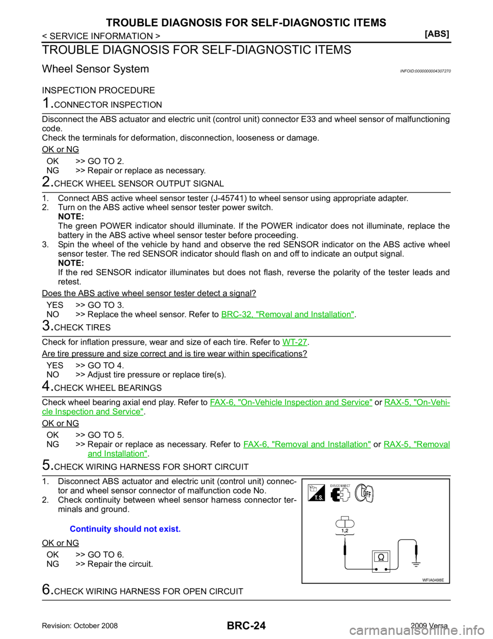
OK >> GO TO 2.
NG >> Repair or replace as necessary. YES >> GO TO 3.
NO >> Replace the wheel sensor. Refer to BRC-32, " Removal and Installation " .
.
Are tire pressure and size correct and is tire wear within specifications? YES >> GO TO 4.
NO >> Adjust tire pressure or replace tire(s). On-Vehicle Inspection and Service " or
RAX-5, " On-Vehi-
cle Inspection and Service " .
OK or NG OK >> GO TO 5.
NG >> Repair or replace as necessary. Refer to FAX-6, " Removal and Installation " or
RAX-5, " Removal
and Installation " .
OK >> GO TO 6.
NG >> Repair the circuit.
Page 987 of 4331

CVT
N
O P
The CVT fluid temperature rises in the range of 50 - 80
°C (122 - 176 °F) during 10 minutes of driving.
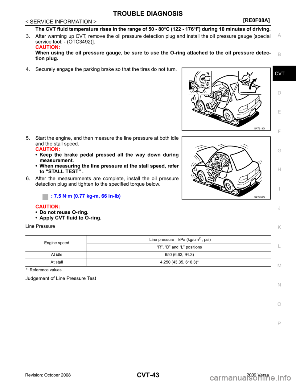
3. After warming up CVT, remove the oil pressure detection plug and install the oil pressure gauge [special service tool: - (OTC3492)].
CAUTION:
When using the oil pressure gauge, be sure to use the O-ring attached to the oil pressure detec-
tion plug.
4. Securely engage the parking brake so that the tires do not turn.
5. Start the engine, and then measure the line pressure at both idle and the stall speed.
CAUTION:
• Keep the brake pedal pressed all the way down during
measurement.
• When measuring the line pressure at the stall speed, refer
to "STALL TEST" .
6. After the measurements are complete, install the oil pressure detection plug and tighten to the specified torque below.
CAUTION:
• Do not reuse O-ring.
• Apply CVT fluid to O-ring.
Line Pressure
*: Reference values
Judgement of Line Pressure Test
Page 1166 of 4331
![NISSAN LATIO 2009 Service Repair Manual CVT-222< SERVICE INFORMATION >
[RE0F08B]
TROUBLE DIAGNOSIS
The CVT fluid temperature rises in the range of 50 - 80 °C (122 - 176 °F) during 10 minutes of driving.
3. After warming up CVT, remove the NISSAN LATIO 2009 Service Repair Manual CVT-222< SERVICE INFORMATION >
[RE0F08B]
TROUBLE DIAGNOSIS
The CVT fluid temperature rises in the range of 50 - 80 °C (122 - 176 °F) during 10 minutes of driving.
3. After warming up CVT, remove the](/manual-img/5/57359/w960_57359-1165.png)
CVT-222< SERVICE INFORMATION >
[RE0F08B]
TROUBLE DIAGNOSIS
The CVT fluid temperature rises in the range of 50 - 80 °C (122 - 176 °F) during 10 minutes of driving.
3. After warming up CVT, remove the oil pressure detection plug and install the oil pressure gauge [special service tool: - (OTC3492)].
CAUTION:
When using the oil pressure gauge, be sure to u se the O-ring attached to the oil pressure detec-
tion plug.
4. Securely engage the parking brake so that the tires do not turn.
5. Start the engine, and then measure the line pressure at both idle and the stall speed.
CAUTION:
• Keep the brake pedal pressed all the way down during
measurement.
• When measuring the line pressure at the stall speed, refer
to "STALL TEST" .
6. After the measurements are complete, install the oil pressure detection plug and tighten to the specified torque below.
CAUTION:
• Do not reuse O-ring.
• Apply CVT fluid to O-ring.
Line Pressure
Judgement of Line Pressure Test SAT513G
: 7.5 N·m (0.77 kg-m, 66 in-lb)
SAT493G
Engine speed
Line pressure kPa (kg/cm
2
, psi)
“R”, “D” and “L” positions
At idle CVT-357, " Line Pressure "
At stall
Page 1314 of 4331
![NISSAN LATIO 2009 Service Repair Manual CONSULT-III display Malfunction Reference page
CAN COMM CIRC [U1000] Malfunction is detected in CAN communication lines.
CAUTION:
Even when there is no malfunct ion on CAN communication system, mal-
f NISSAN LATIO 2009 Service Repair Manual CONSULT-III display Malfunction Reference page
CAN COMM CIRC [U1000] Malfunction is detected in CAN communication lines.
CAUTION:
Even when there is no malfunct ion on CAN communication system, mal-
f](/manual-img/5/57359/w960_57359-1313.png)
CONSULT-III display Malfunction Reference page
CAN COMM CIRC [U1000] Malfunction is detected in CAN communication lines.
CAUTION:
Even when there is no malfunct ion on CAN communication system, mal-
function may be misinterpreted when battery has low voltage (when main-
taining 7 - 8 V for about 2 seconds) or 10A fuse [No. 14, located in the fuse
block (J/B)] is removed. DI-18VEHICLE SPEED CIRC [B2205]
Malfunction is detected when an erroneous speed signal is input.
CAUTION:
Even when there is no malfunction on speed signal system, malfunctions
may be misinterpreted when battery has low voltage (when maintaining 7
- 8 V for about 2 seconds). DI-15Display item [Unit]
MAIN
SIGNALS SELECTION
FROM MENU Contents
SPEED METER [km/h] X X The value of vehicle speed sign
al, which is input from ABS ac-
tuator and electric unit (control unit).
SPEED OUTPUT [km/h] X X The value of vehicle speed signal, which is transmitted to each
unit with CAN communication.
TACHO METER [rpm] X X The value of engine speed signal, which is input from ECM.
W TEMP METER [ °C] X X The value of engine coolant temperature signal, which is input
from ECM.
FUEL METER [lit.] X X The value, which processes a resistance signal from fuel
gauge.
DISTANCE [km] X X The value, which is calculated by vehicle speed signal from
ABS actuator and electric unit (con trol unit), fuel gauge and fuel
consumption signal from ECM.
FUEL W/L [ON/OFF] X X Indicates [ON/OFF] condition of low-fuel warning lamp.
C-ENG W/L [ON/OFF] X Indicates [ON/OFF] condition of malfunction indicator lamp
(MIL).
AIR PRES W/L X Indicates [ON/OFF] condition of low tire pressure warning lamp.
SEAT BELT W/L X Indicates [ON/OFF] condition of seat belt warning lamp.
BUZZER [ON/OFF] X X Indicates [ON/ OFF] condition of buzzer.
DOOR W/L [ON/OFF] X Indicates [ON/OFF] condition of door warning lamp.
HI-BEAM IND [ON/OFF] X Indicat es [ON/OFF] condition of high beam indicator lamp.
Page 2011 of 4331
![NISSAN LATIO 2009 Service Repair Manual DTC P0101 MAF SENSOR
EC-655
< SERVICE INFOMATION >
[MR TYPE 1] C
D E
F
G H
I
J
K L
M A EC
NP
O
DTC P0101 MAF SENSOR
Component Description INFOID:0000000004537112
The mass air flow sensor (1) is NISSAN LATIO 2009 Service Repair Manual DTC P0101 MAF SENSOR
EC-655
< SERVICE INFOMATION >
[MR TYPE 1] C
D E
F
G H
I
J
K L
M A EC
NP
O
DTC P0101 MAF SENSOR
Component Description INFOID:0000000004537112
The mass air flow sensor (1) is](/manual-img/5/57359/w960_57359-2010.png)
DTC P0101 MAF SENSOR
EC-655
< SERVICE INFOMATION >
[MR TYPE 1] C
D E
F
G H
I
J
K L
M A EC
NP
O
DTC P0101 MAF SENSOR
Component Description INFOID:0000000004537112
The mass air flow sensor (1) is plac ed in the stream of intake air. It
measures the intake flow rate by measuring a part of the entire
intake flow. The mass air flow sens or controls the temperature of the
hot wire to a certain amount. The heat generated by the hot wire is
reduced as the intake air flows around it. The more air, the greater
the heat loss.
Therefore, the electric current supplied to hot wire is changed to
maintain the temperature of the hot wire as air flow increases. The
ECM detects the air flow by means of this current change.
CONSULT-III Reference Val ue in Data Monitor Mode INFOID:0000000004537113
Specification data are reference values.
On Board Diagnosis Logic INFOID:0000000004537114
DTC Confirmation Procedure INFOID:0000000004537115
Perform PROCEDURE FOR MALFUNCTION A first.
If the DTC cannot be confirmed, perform PROCEDURE FOR MALFUNCTION B.
NOTE:
If DTC Confirmation Procedure has been previously conduc ted, always turn ignition switch OFF and wait at
least 10 seconds before conducting the next test. PBIA9559J
MONITOR ITEM CONDITION SPECIFICATION
MAS A/F SE-B1 • See EC-618 .
CAL/LD VALUE • Engine: After warming up
• Shift lever: P or N (A/T, CVT), Neutral (M/T)
• Air conditioner switch: OFF
• No load Idle 10% - 35%
2,500 rpm 10% - 35%
MASS AIRFLOW • Engine: After warming up
• Shift lever: P or N (A/T, CVT),
Neutral (M/T)
• Air conditioner switch: OFF
• No load Idle 1.0 - 4.0 g·m/s
2,500 rpm 4.0 - 10.0 g·m/s DTC No. Trouble diagnosis name DTC detecting condition Possible cause
P0101
0101 Mass air flow sensor cir-
cuit range/performance A)
A high voltage from the sensor is sent to ECM
under light load driving condition. • Harness or connectors
(Mass air flow sensor circuit is
open or shorted.)
• Mass air flow sensor
• EVAP control system pressure
sensor
• Intake air temperature sensor
B) A low voltage from the sensor is sent to ECM un-
der heavy load driving condition. • Harness or connectors
(Mass air flow sensor circuit is
open or shorted.)
• Intake air leaks
• Mass air flow sensor
• EVAP control system pressure sensor
• Intake air temperature sensor
Page 2526 of 4331
![NISSAN LATIO 2009 Service Repair Manual EC-1170< SERVICE INFOMATION >
[MR TYPE 2]
DTC P0101 MAF SENSOR
DTC P0101 MAF SENSOR
Component Description INFOID:0000000004499998
The mass air flow sensor (1) is placed in the stream of in NISSAN LATIO 2009 Service Repair Manual EC-1170< SERVICE INFOMATION >
[MR TYPE 2]
DTC P0101 MAF SENSOR
DTC P0101 MAF SENSOR
Component Description INFOID:0000000004499998
The mass air flow sensor (1) is placed in the stream of in](/manual-img/5/57359/w960_57359-2525.png)
EC-1170< SERVICE INFOMATION >
[MR TYPE 2]
DTC P0101 MAF SENSOR
DTC P0101 MAF SENSOR
Component Description INFOID:0000000004499998
The mass air flow sensor (1) is placed in the stream of intake air. It
measures the intake flow rate by measuring a part of the entire
intake flow. The mass air flow sensor controls the temperature of the
hot wire to a certain amount. The heat generated by the hot wire is
reduced as the intake air flows around it. The more air, the greater
the heat loss.
Therefore, the electric current supplied to hot wire is changed to
maintain the temperature of the hot wire as air flow increases. The
ECM detects the air flow by means of this current change.
CONSULT-III Reference Value in Data Monitor Mode INFOID:0000000004499999
Specification data are reference values.
On Board Diagn osis Logic INFOID:0000000004500000
DTC Confirmation Procedure INFOID:0000000004500001
Perform PROCEDURE FOR MALFUNCTION A first.
If the DTC cannot be confirmed, perform PROCEDURE FOR MALFUNCTION B.
NOTE:
If DTC Confirmation Procedure has been previously conduc ted, always turn ignition switch OFF and wait at
least 10 seconds before conducting the next test. PBIA9559J
MONITOR ITEM CONDITION SPECIFICATION
MAS A/F SE-B1 • See EC-1130 .
CAL/LD VALUE • Engine: After warming up
• Shift lever: P or N (A/T, CVT), Neutral (M/T)
• Air conditioner switch: OFF
• No load Idle 10% - 35%
2,500 rpm 10% - 35%
MASS AIRFLOW • Engine: After warming up
• Shift lever: P or N (A/T, CVT),
Neutral (M/T)
• Air conditioner switch: OFF
• No load Idle 1.0 - 4.0 g·m/s
2,500 rpm 4.0 - 10.0 g·m/s DTC No. Trouble diagnosis name DTC detecting condition Possible cause
P0101
0101 Mass air flow sensor cir-
cuit range/performance A)
A high voltage from the sensor is sent to ECM
under light load driving condition. • Harness or connectors
(Mass air flow sensor circuit is
open or shorted.)
• Mass air flow sensor
• EVAP control system pressure
sensor
• Intake air temperature sensor
B) A low voltage from the sensor is sent to ECM un-
der heavy load driving condition. • Harness or connectors
(Mass air flow sensor circuit is
open or shorted.)
• Intake air leaks
• Mass air flow sensor
• EVAP control system pressure sensor
• Intake air temperature sensor