2009 NISSAN LATIO battery location
[x] Cancel search: battery locationPage 2745 of 4331

EC
NP
O
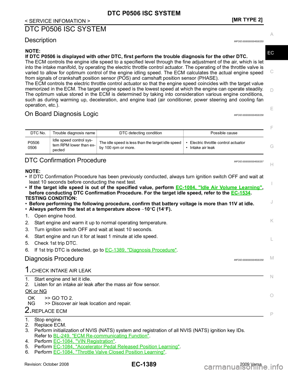
DTC P0506 ISC SYSTEM
Description INFOID:0000000004500255
NOTE:
If DTC P0506 is displayed with ot her DTC, first perform the trouble diagnosis for the other DTC.
The ECM controls the engine idle speed to a specified leve l through the fine adjustment of the air, which is let
into the intake manifold, by operating the electric thrott le control actuator. The operating of the throttle valve is
varied to allow for optimum control of the engine id ling speed. The ECM calculates the actual engine speed
from signals of crankshaft position sensor (POS) and camshaft position sensor (PHASE).
The ECM controls the electric throttle control actuator so that the engine speed coincides with the target value
memorized in the ECM. The target engine speed is t he lowest speed at which the engine can operate steadily.
The optimum value stored in the ECM is determined by taking into consideration various engine conditions,
such as during warming up, deceleration, and engine load (air conditioner, power steering and cooling fan
operation, etc.).
On Board Diagnosis Logic INFOID:0000000004500256
DTC Confirmation Procedure INFOID:0000000004500257
NOTE:
• If DTC Confirmation Procedure has been previously conduc ted, always turn ignition switch OFF and wait at
least 10 seconds before conducting the next test.
• If the target idle speed is out of the specified value, perform EC-1084, " Idle Air Volume Learning " ,
before conducting DTC Confirmation Procedure. For the target idle speed, refer to the EC-1534 .
TESTING CONDITION:
• Before performing the following procedure, confirm that battery voltage is more than 11V at idle.
• Always perform the test at a temperature above −10 °C (14 °F).
1. Open engine hood.
2. Start engine and warm it up to normal operating temperature.
3. Turn ignition switch OFF and wait at least 10 seconds.
4. Start engine and run it for at least 1 minute at idle speed.
5. Check 1st trip DTC.
6. If 1st trip DTC is detected, go to EC-1389, " Diagnosis Procedure " .
Diagnosis Procedure INFOID:0000000004500258OK >> GO TO 2.
NG >> Discover air leak location and repair. ECM Re-communicating Function " .
4. Perform EC-1084, " VIN Registration " .
5. Perform EC-1084, " Accelerator Pedal Released Position Learning " .
6. Perform EC-1084, " Throttle Valve Closed Position Learning " .
DTC No. Trouble diagnosis name DTC detecting condition Possible cause
P0506
0506 Idle speed control sys-
tem RPM lower than ex-
pected The idle speed is less than the target idle speed
by 100 rpm or more. • Electric throttle control actuator
• Intake air leak
Page 2747 of 4331

EC
NP
O
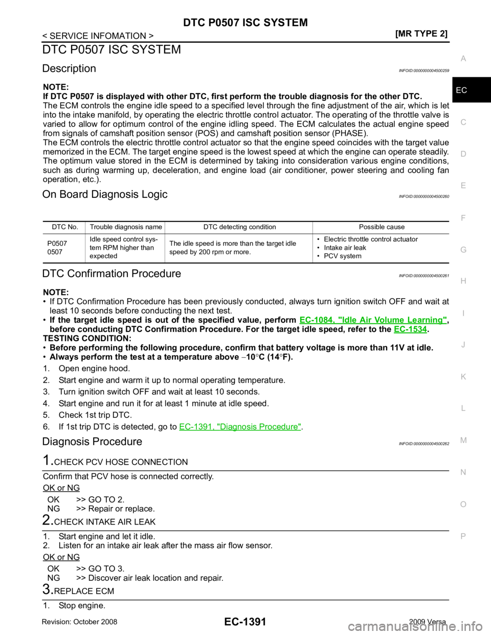
DTC P0507 ISC SYSTEM
Description INFOID:0000000004500259
NOTE:
If DTC P0507 is displayed with ot her DTC, first perform the trouble diagnosis for the other DTC.
The ECM controls the engine idle speed to a specified leve l through the fine adjustment of the air, which is let
into the intake manifold, by operating the electric thrott le control actuator. The operating of the throttle valve is
varied to allow for optimum control of the engine id ling speed. The ECM calculates the actual engine speed
from signals of camshaft position sensor (POS) and camshaft position sensor (PHASE).
The ECM controls the electric throttle control actuator so that the engine speed coincides with the target value
memorized in the ECM. The target engine speed is t he lowest speed at which the engine can operate steadily.
The optimum value stored in the ECM is determined by taking into consideration various engine conditions,
such as during warming up, deceleration, and engine load (air conditioner, power steering and cooling fan
operation, etc.).
On Board Diagnosis Logic INFOID:0000000004500260
DTC Confirmation Procedure INFOID:0000000004500261
NOTE:
• If DTC Confirmation Procedure has been previously conduc ted, always turn ignition switch OFF and wait at
least 10 seconds before conducting the next test.
• If the target idle speed is out of the specified value, perform EC-1084, " Idle Air Volume Learning " ,
before conducting DTC Confirmation Procedure. For the target idle speed, refer to the EC-1534 .
TESTING CONDITION:
• Before performing the following procedure, confirm that battery voltage is more than 11V at idle.
• Always perform the test at a temperature above −10 °C (14 °F).
1. Open engine hood.
2. Start engine and warm it up to normal operating temperature.
3. Turn ignition switch OFF and wait at least 10 seconds.
4. Start engine and run it for at least 1 minute at idle speed.
5. Check 1st trip DTC.
6. If 1st trip DTC is detected, go to EC-1391, " Diagnosis Procedure " .
Diagnosis Procedure INFOID:0000000004500262OK >> GO TO 2.
NG >> Repair or replace. OK >> GO TO 3.
NG >> Discover air leak location and repair.
Page 3886 of 4331

MTC
N
O P
CONTENTS
MANUAL AIR CONDITIONER
SERVICE INFORMATION .. ..........................3
PRECAUTIONS .............................................. .....3
Precaution for Supplemental Restraint System
(SRS) "AIR BAG" and "SEAT BELT PRE-TEN-
SIONER" ............................................................. ......
3
Precaution Necessary fo r Steering Wheel Rota-
tion After Battery Disconnect ............................... ......
3
Precaution for Procedure without Cowl Top Cover ......4
Precaution for Working with HFC-134a (R-134a) ......4
General Refrigerant Precaution .......................... ......4
Oil Precaution ...................................................... ......5
Precaution for Refrigeran t Connection ......................5
Precaution for Service of Compressor ................ ......7
Precaution for Service Equipment ....................... ......8
Precaution for Leak Detection Dye ..................... ......9
PREPARATION .............................................. ....11
HFC-134a (R-134a) Service Tool and Equipment ....11
Commercial Service Tool .................................... ....13
REFRIGERATION SYSTEM .......................... ....15
Refrigerant Cycle ................................................ ....15
Refrigerant System Protec tion ................................15
Component Part Location ................................... ....16
OIL .................................................................. ....17
Maintenance of Oil Quantity in Compressor ....... ....17
AIR CONDITIONER CONTROL ..................... ....19
Control Operation ................................................ ....19
Discharge Air Flow .............................................. ....20
System Description ............................................. ....20
TROUBLE DIAGNOSIS ................................. ....22
CONSULT-II Function (BCM) .............................. ....22
How to Perform Trouble Diagnosis for Quick and
Accurate Repair ........... ...........................................
22
Component Parts and Harness Connector Loca-
tion ...................................................................... ....
23
Schematic ........................................................... ....25
Wiring Diagram - Heater - ................................... ....26 Wiring Diagram - A/C,M - ....................................
....27
Operational Check ............................................... ....30
Mode Door ........................................................... ....31
Air Mix Door ......................................................... ....32
Intake Door .......................................................... ....33
Front Blower Motor Circuit .......................................33
Magnet Clutch Circuit (If Equipped) ..................... ....37
Insufficient Cooling .............................................. ....45
Insufficient Heating .............................................. ....52
Noise ................................................................... ....53
CONTROLLER .................................................. 55
Removal and Installation ..................................... ....55
Disassembly and Assembly ................................. ....56
THERMO CONTROL AMPLIFIER .................... 57
Removal and Installation ..................................... ....57
A/C UNIT ASSEMBLY ...................................... 58
Removal and Installation ..................................... ....58
Disassembly and Assembly ................................. ....60
BLOWER MOTOR ............................................ 62
Removal and Installation ..................................... ....62
INTAKE DOOR .................................................. 63
Intake Door Cable Adjustment ............................. ....63
AIR MIX DOOR ................................................. 64
Air Mix Door Cable Adjustment ........................... ....64
MODE DOOR .................................................... 65
Mode Door Cable Adjustment ............................. ....65
BLOWER FAN RESISTOR ............................... 66
Removal and Installation ..................................... ....66
HEATER CORE ................................................. 67
Removal and Installation ..................................... ....67
AIR CONDITIONER FILTER ............................. 68
Removal and Installation ..................................... ....68
Page 4176 of 4331

SE
N
O P
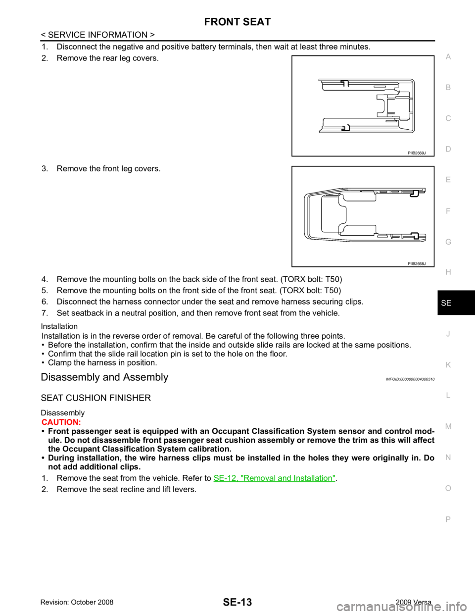
1. Disconnect the negative and positive battery term
inals, then wait at least three minutes.
2. Remove the rear leg covers.
3. Remove the front leg covers.
4. Remove the mounting bolts on the back si de of the front seat. (TORX bolt: T50)
5. Remove the mounting bolts on the front side of the front seat. (TORX bolt: T50)
6. Disconnect the harness connector under the seat and remove harness securing clips.
7. Set seatback in a neutral position, and t hen remove front seat from the vehicle.
Installation Installation is in the reverse order of removal. Be careful of the following three points.
• Before the installation, confirm that the inside and outside slide rails are locked at the same positions.
• Confirm that the slide rail location pin is set to the hole on the floor.
• Clamp the harness in position.
Disassembly and Assembly INFOID:0000000004306510
SEAT CUSHION FINISHER
Disassembly CAUTION:
• Front passenger seat is equipped with an Occu pant Classification System sensor and control mod-
ule. Do not disassemble front passenger seat cushion assembly or remove the trim as this will affect
the Occupant Classificatio n System calibration.
• During installation, the wire harn ess clips must be installed in the holes they were originally in. Do
not add additional clips.
1. Remove the seat from the vehicle. Refer to SE-12, " Removal and Installation " .
2. Remove the seat recline and lift levers. PIIB2668J
Page 4191 of 4331

SRS
N
O P
CONTENTS
SUPPLEMENTAL RESTRAINT SYSTEM (SRS)
PRECAUTION ....... ........................................2
PRECAUTIONS .............................................. .....2
Precaution for Supplemental Restraint System
(SRS) "AIR BAG" and "SEAT BELT PRE-TEN-
SIONER" ............................................................. ......
2
Precaution for SRS "AIR BAG" and "SEAT BELT
PRE-TENSIONER" Service ................................ ......
2
Precaution Necessary fo r Steering Wheel Rota-
tion After Battery Disconnect ............................... ......
2
Occupant Classification System Precaution ....... ......3
SYMPTOM DIAGNOSIS ..... ..........................4
SUPPLEMENTAL RESTRAINT SYSTEM
(SRS) .............................................................. .....
4
SRS Configuration .............................................. ......4
Driver Air Bag Module ......................................... ......5
Front Passenger Air Bag Module ..............................5
Front Side Air Bag ............................................... ......5
Side Curtain Air Bag ............................................ ......5
Front Seat Belt Pre-tensioner with Load Limiter . ......6
Occupant Classification System (OCS) .............. ......6
Direct-connect SRS Component Connectors ...... ......7
TROUBLE DIAGNOSIS ................................. .....8
Trouble Diagnosis Introduction ........................... ......8
SRS Component Parts Location ......................... ....10
Schematic ........................................................... ....11
Wiring Diagram - SRS- ........................................ ....12
CONSULT-III Function (AIR BAG) ...................... ....17
Self-Diagnosis Function (Without CONSULT-III) .... 18
SRS Operation Check ......................................... ....19
Trouble Diagnosis with CONSULT-III ................. ....20
Trouble Diagnosis without CONSULT-III ............ ....28
Trouble Diagnosis: "AIR BAG" Warning Lamp
Does Not Turn Off ............................................... ....
31 Trouble Diagnosis: "AIR BAG" Warning Lamp
Does Not Turn On ............................................... ....
32
ON-VEHICLE REPAIR ..... ............................34
DRIVER AIR BAG MODULE ............................ 34
Removal and Installation ..................................... ....34
SPIRAL CABLE ................................................ 37
Removal and Installation ..................................... ....37
FRONT PASSENGER AIR BAG MODULE ...... 39
Removal and Installation ..................................... ....39
SIDE CURTAIN AIR BAG MODULE ................ 40
Component .......................................................... ....40
Removal and Installation ..................................... ....40
CRASH ZONE SEN SOR ................................... 42
Removal and Installation ..................................... ....42
SIDE AIR BAG (SATELLITE) SENSOR ........... 43
Removal and Installation ..................................... ....43
FRONT SEAT BELT PRE-TENSIONER ........... 44
Removal and Installation ..................................... ....44
DIAGNOSIS SENSOR UNIT ............................. 45
Removal and Installation ..................................... ....45
OCCUPANT CLASSIFICATION SYSTEM
CONTROL UNIT ................................................ 46
Removal and Installation ..................................... ....46
COLLISION DIAGNOSIS .................................. 47
For Frontal Collision ............................................ ....47
For Side and Rollover Colli sion ...............................48
Page 4241 of 4331

STC
N
O P
CONTENTS
STEERING CONTROL SYSTEM
EPS
SERVICE INFORMATION .. ..........................
2
PRECAUTIONS .............................................. .....2
Precaution for Supplemental Restraint System
(SRS) "AIR BAG" and "SEAT BELT PRE-TEN-
SIONER" ............................................................. ......
2
Precaution Necessary fo r Steering Wheel Rota-
tion After Battery Disconnect ............................... ......
2
Service Notice or Precau tion for EPS System ..........3
EPS SYSTEM ... .............................................. .....4
System Description ............................................. ......4
Schematic ........................................................... ......5
CAN Communication ........................................... ......5
TROUBLE DIAGNOSIS ................................. .....6
Fail-Safe Function ............................................... ......6
How to Perform Trouble Diagnosis ..................... ......6
Component Parts Location .................................. ......7
Wiring Diagram - EPS - ... ..........................................8
EPS Control Unit Input/O utput Signal Reference
Value ................................................................... ......
9 EPS Terminal and Reference Value ....................
....10
CONSULT-III Function ( EPS) ..................................11
Symptom Chart .................................................... ....13
TROUBLE DIAGNOSIS FOR SYSTEM ............ 14
DTC C1601 BATTERY VOLT .............................. ....14
DTC C1604 TORQUE SENSOR ......................... ....15
DTC C1606 EPS MOTOR ................................... ....16
DTC C1607 EEPROM ......................................... ....17
DTC C1608 CONTROL UNIT .............................. ....17
DTC C1609 CAN VHCL SPEED ......................... ....18
DTC C1610 CAN ENG RPM ............................... ....19
DTC U1000 CAN COMM CIRCUIT ..................... ....19
Component Inspection ......................................... ....19
TROUBLE DIAGNOSIS FOR SYMPTOMS ...... 21
EPS Warning Lamp Does Not Turn ON ..................21
EPS Warning Lamp Does Not Turn OFF ................21
Steering Wheel Turning Force Is Heavy or Light . ....22
Unbalance Steering Wheel Turning Force and Re-
turn Between Right and Left ................................ ....
23
Unbalance Steering Wheel Turning Force (Torque
Variation) ............................................................. ....
24
Page 4281 of 4331

OK >> GO TO 4.
NG >> Repair or replace damaged parts. OK >> Carry out self-diagnosis.
NG >> Replace battery in transmitter activation tool.
Self-Diagnosis (With CONSULT-III) INFOID:0000000004307329
DESCRIPTION
During driving, the tire pressure monitoring system receives the signal transmitted from the transmitter
installed in each wheel, and turns on the low tire pressure warning lamp when the tire pressure becomes low.
The control unit (BCM) for this system has pressure judgement and self-diagnosis functions.
FUNCTION
When the tire pressure monitoring syst em detects low inflation pressure or an internal malfunction, the low tire
pressure warning lamp in the combination meter comes on. The malfunction location is indicated by the low
tire pressure warning lamp flashing and the buzzer sounding.
CONSULT-III Application to Tire Pressure Monitoring System
× : Applicable
– : Not applicable
Self-Diagnostic Results Mode ITEM SELF-DIAGNOSTIC RESULTS DATA MONITOR
Front - Left transmitter × ×
Front - Right transmitter × ×
Rear - Left transmitter × ×
Rear - Right transmitter × ×
Warning lamp — ×
Vehicle speed × ×
Buzzer (in combination meter) — ×
CAN Communication × × 8, " System Description " .
Page 4282 of 4331

WT
N
O P
NOTE:
Before performing the self-diagnosis, be sure to register the ID or else the actual malfunction location may be different from that dis-
played on CONSULT-III.
Data Monitor Mode
NOTE:
Before performing the self-diagnosis, be sure to register the ID, or the actual malfunction location may be different from that displayed on
CONSULT-III.
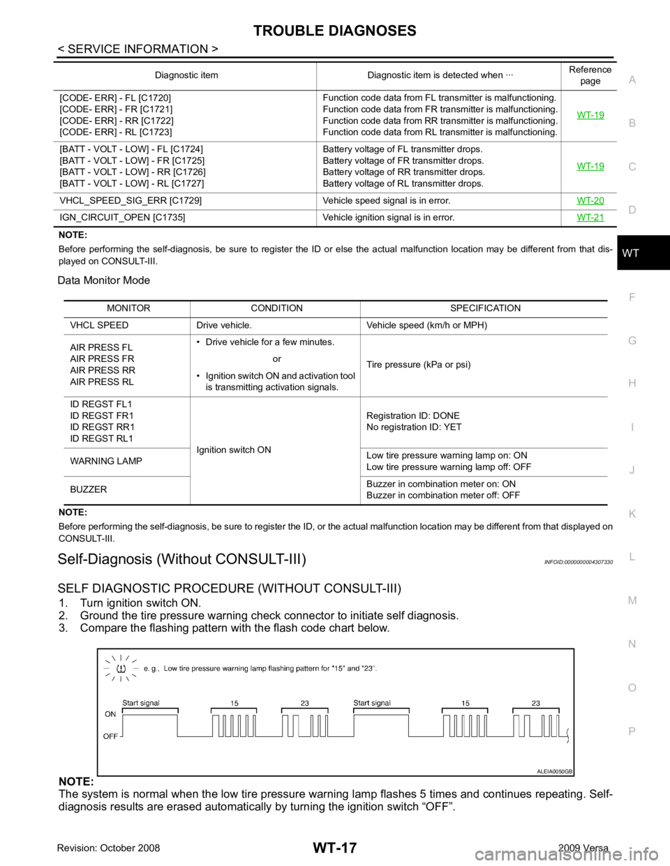
Self-Diagnosis (Without CONSULT-III) INFOID:0000000004307330
SELF DIAGNOSTIC PROCE DURE (WITHOUT CONSULT-III)
1. Turn ignition switch ON.
2. Ground the tire pressure warning check connector to initiate self diagnosis.
3. Compare the flashing pattern with the flash code chart below.
NOTE:
The system is normal when the low tire pressure warni ng lamp flashes 5 times and continues repeating. Self-
diagnosis results are erased automatically by turning the ignition switch “OFF”.
[CODE- ERR] - FL [C1720]
[CODE- ERR] - FR [C1721]
[CODE- ERR] - RR [C1722]
[CODE- ERR] - RL [C1723] Function code data from FL transmitter is malfunctioning.
Function code data from FR transmitter is malfunctioning.
Function code data from RR transmitter is malfunctioning.
Function code data from RL transmitter is malfunctioning. WT-19[BATT - VOLT - LOW] - FL [C1724]
[BATT - VOLT - LOW] - FR [C1725]
[BATT - VOLT - LOW] - RR [C1726]
[BATT - VOLT - LOW] - RL [C1727] Battery voltage of FL transmitter drops.
Battery voltage of FR transmitter drops.
Battery voltage of RR transmitter drops.
Battery voltage of RL transmitter drops. WT-19VHCL_SPEED_SIG_ERR [C1729] Vehicle
speed signal is in error.WT-20IGN_CIRCUIT_OPEN [C1735] Vehicle
ignition signal is in error. WT-21Diagnostic item Diagnostic item is detected when ···
Reference
page MONITOR CONDITION SPECIFICATION
VHCL SPEED Drive vehicle. Vehicle speed (km/h or MPH)
AIR PRESS FL
AIR PRESS FR
AIR PRESS RR
AIR PRESS RL • Drive vehicle for a few minutes.
Tire pressure (kPa or psi)
or
• Ignition switch ON and activation tool is transmitting activation signals.
ID REGST FL1
ID REGST FR1
ID REGST RR1
ID REGST RL1 Ignition switch ON Registration ID: DONE
No registration ID: YET
WARNING LAMP Low tire pressure
warning lamp on: ON
Low tire pressure warning lamp off: OFF
BUZZER Buzzer in combination meter on: ON
Buzzer in combination meter off: OFF