2009 NISSAN LATIO ignition
[x] Cancel search: ignitionPage 4092 of 4331
RF
N
O P
FUNCTION DIAGNOSIS
TROUBLE DIAGNOSIS
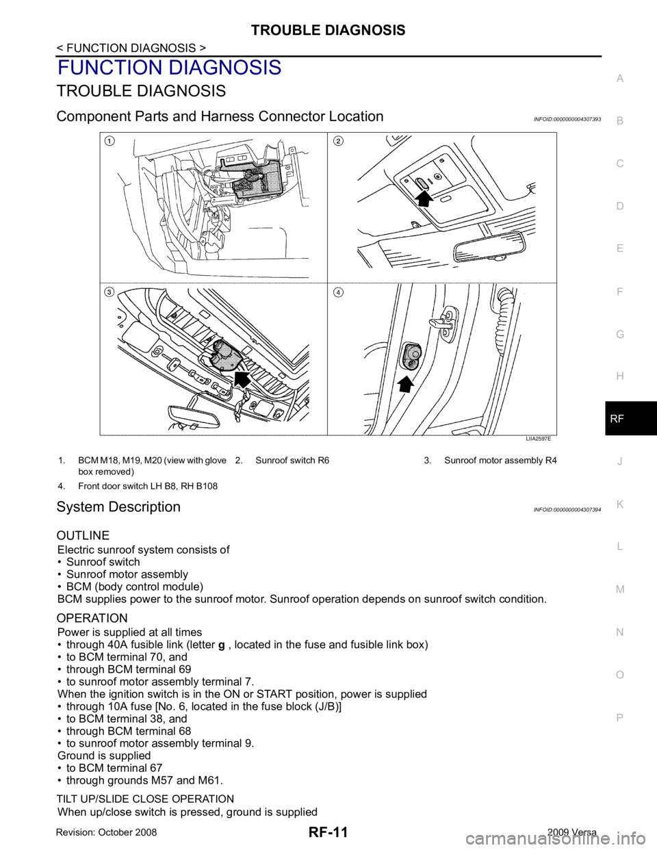
Component Parts and Har ness Connector Location INFOID:0000000004307393
System Description INFOID:0000000004307394
OUTLINE Electric sunroof system consists of
• Sunroof switch
• Sunroof motor assembly
• BCM (body control module)
BCM supplies power to the sunroof motor. S unroof operation depends on sunroof switch condition.
OPERATION Power is supplied at all times
• through 40A fusible link (letter g , located in the fuse and fusible link box)
• to BCM terminal 70, and
• through BCM terminal 69
• to sunroof motor assembly terminal 7.
When the ignition switch is in the ON or START position, power is supplied
• through 10A fuse [No. 6, located in the fuse block (J/B)]
• to BCM terminal 38, and
• through BCM terminal 68
• to sunroof motor assembly terminal 9.
Ground is supplied
• to BCM terminal 67
• through grounds M57 and M61.
TILT UP/SLIDE CLOSE OPERATION When up/close switch is pressed, ground is supplied
Page 4097 of 4331

System Description " .
3. According to the trouble diagnosis chart, repa ir or replace the cause of the malfunction.
Refer to RF-17, " Trouble Diagnosis Chart by Symptom " .
4. Does sunroof system operate normally? If Yes, GO TO 5. If No, GO TO 3.
5. Inspection End.
CONSULT-III Function (BCM) INFOID:0000000004307400
CONSULT-III can display each diagnostic item us ing the diagnostic test modes shown following.
Terminal
Wire col-
or Item Condition
Voltage
(Approx.)
1 R Sunroof switch (UP/CLOSE) signal Ignition switch ON and sunroof
switch in UP/CLOSE position 0
Ignition switch ON and sunroof
switch in OFF position Battery voltage
5 G Sunroof switch (DOWN/OPEN) signal Ignition switch ON and sunroof
switch in DOWN/OPEN position 0
Ignition switch ON and sunroof
switch in OFF position Battery voltage
7 P BAT power supply — Battery voltage
8 O Vehicle speed signal Speedometer operated [when ve-
hicle speed is approx. 40 km/h (25 MPH)]
9 W RAP signal Ignition switch ON Battery voltage
Within 45 seconds after ignition switch is turned OFF Battery voltage
When front door LH or RH is
opened while retained power is
operating 0
10 B Ground — 0
Page 4098 of 4331
RF
N
O P
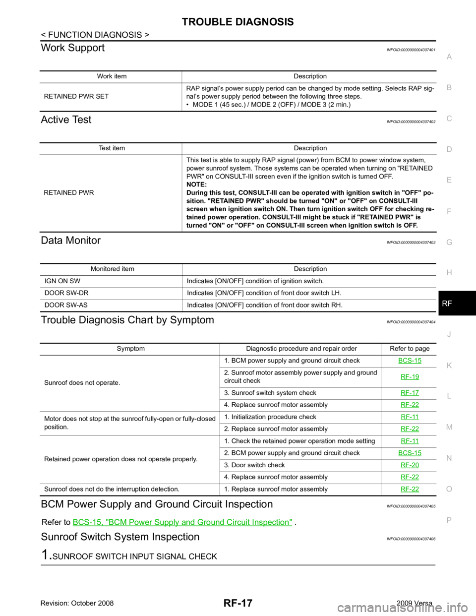
Work Support
INFOID:0000000004307401
Active Test INFOID:0000000004307402
Data Monitor INFOID:0000000004307403
Trouble Diagnosis Chart by Symptom INFOID:0000000004307404
BCM Power Supply and Gr ound Circuit Inspection INFOID:0000000004307405
Refer to BCS-15, " BCM Power Supply and Ground Circuit Inspection " .
Sunroof Switch System Inspection INFOID:0000000004307406Test item Description
RETAINED PWR This test is able to supply RAP signal (power) from BCM to power window system,
power sunroof system. Those systems can be operated when turning on "RETAINED
PWR" on CONSULT-III screen even if the ignition switch is turned OFF.
NOTE:
During this test, CONSULT-III can be operated with ignition switch in "OFF" po-
sition. "RETAINED PWR" should be turned "ON" or "OFF" on CONSULT-III
screen when ignition switch ON. Then turn ignition switch OFF for checking re-
tained power operation. CONSULT-III might be stuck if "RETAINED PWR" is
turned "ON" or "OFF" on CONSULT-III screen when ignition switch is OFF. Symptom Diagnostic procedure and repair order Refer to page
Sunroof does not operate. 1. BCM power supply and ground circuit check
BCS-15 2. Sunroof motor assembly power supply and ground
circuit check RF-19 3. Sunroof switch system check
RF-17 4. Replace sunroof motor assembly
RF-22Motor does not stop at the sunroof fully-open or fully-closed
position. 1. Initialization procedure check
RF-11 2. Replace sunroof motor assembly
RF-22Retained power operation does not operate properly.
1. Check the retained power operation mode setting
RF-11 2. BCM power supply and ground circuit check
BCS-15 3. Door switch check
RF-20 4. Replace sunroof motor assembly
RF-22Sunroof does not do the interruption detection. 1. Replace sunroof motor assembly
RF-22
Page 4102 of 4331
RF
N
O P
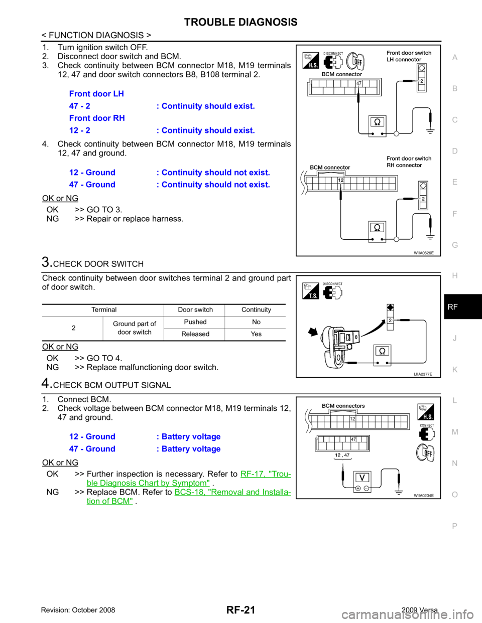
1. Turn ignition switch OFF.
2. Disconnect door switch and BCM.
3. Check continuity between BCM connector M18, M19 terminals
12, 47 and door switch connectors B8, B108 terminal 2.
4. Check continuity between BCM connector M18, M19 terminals 12, 47 and ground.
OK or NG OK >> GO TO 3.
NG >> Repair or replace harness. OK >> GO TO 4.
NG >> Replace malfunctioning door switch. OK >> Further inspection is necessary. Refer to
RF-17, " Trou-
ble Diagnosis Chart by Symptom " .
NG >> Replace BCM. Refer to BCS-18, " Removal and Installa-
tion of BCM " .
Front door LH
47 - 2 : Continuity should exist.
Front door RH
12 - 2 : Continuity should exist.
12 - Ground : Continuity should not exist.
47 - Ground : Continuity should not exist.
Page 4114 of 4331
RSU
N
O P
5. When the repair work is completed, return the ignition switch to the
″LOCK ″ position before connecting
the battery cables. (At this time, the steering lock mechanism will engage.)
6. Perform a self-diagnosis check of al l control units using CONSULT-III.
Precaution for Rear Suspension INFOID:0000000004305875
• When installing the rubber bushings, the final tightening must be done under unladen condition and with the tires on level ground. Oil will shorten the life of the rubber bushings, so wipe off any spilled oil immediately.
• Unladen condition means the fuel tank, engine coolant and l ubricants are at the full specification. The spare
tire, jack, hand tools, and mats are in their designated positions.
• After installing suspension components, check the wheel alignment.
• Caulking nuts are not reusable. Always use new caulking nuts for installation. New caulking nuts are pre-
oiled, do not apply any additional lubrication.
Page 4133 of 4331
SB
N
O P
• The seat belt was damaged in an accident. (i.e. torn webbing, bent retractor or guide, etc.)
• The seat belt attaching point was damaged in an accident. Inspect the seat belt attaching area for damage or distortion and repair as necessary before installing a new seat belt assembly.
• Anchor bolts are deformed or worn out.
• The seat belt pre-tensioner should be replaced even if the seat belts are not in use during a frontal collision
in which the air bags are deployed.
PRELIMINARY CHECKS 1. Check the seat belt warning lamp/chime for proper operation as follows:
a. Switch ignition ON. The seat belt warning lamp should illuminate. Also, the seat belt warning chime should sound for about seven seconds.
b. Fasten driver's seat belt. The seat belt warni ng lamp should go out and the chime (if sounding) should
stop.
2. If the air bag warning lamp is blinking, conduct self-diagnosis using CONSULT-II, and air bag warning
lamp. Refer to SRS-19, " SRS Operation Check " .
3. Check that the seat belt retractor, seat belt anchor and buckle bolts are securely attached.
4. Check the shoulder seat belt guide and shoulder belt height adjuster for front seats. Make sure guide
swivels freely and that webbing lays flat and does not bind in guide. Make sure height adjuster operates
properly and holds securely.
5. Check retractor operation:
a. Fully extend the seat belt webbing and check for twists, tears or other damage.
b. Allow the seat belt to retract. Make sure that webbing returns smoothly and completely into the retractor. If the seat belt does not return smoothly, wipe the inside of the loops with a clean paper cloth. Dirt build-up
in the loops of the upper anchors can caus e the seat belts to retract slowly.
c. Fasten the seat belt. Check the seat belt returns sm oothly and completely to the retractor. If the webbing
does not return smoothly, the cause may be an accu mulation of dust or dirt. Use the “SEAT BELT TAPE
SET” and perform the following steps.
Inspect the front seat belt though-anchor
1. Pull the seat belt out to a length of 500 mm (19.69 in) or more.
2. Use a clip or other device to attach t he seat belt at the center pillar webbing opening.
3. Pass a thin wire though the D-ring anchor webbing opening. Hold both ends of the wire and pull taut while moving it up and down several times along the webbing opening surface to remove matter stuck
there.
4. Any dirt that cannot be removed with the wire can be removed by cleaning the opening with a clean
cloth.
5. Apply tape at the point where the webbing contacts the though-anchor webbing opening. NOTE:
Apply the tape so that there is no looseness or wrinkling.
6. Remove the clip attaching the seat bel t and check that the webbing returns smoothly.
6. Repeat steps above as necessary to check the other seat belts.
SEAT BELT RETRACTOR ON-VEHICLE CHECK
Emergency Locking Retractors (ELR) and Automatic Locking Retractors (ALR)
NOTE:
All seat belt retractors are of the Emergency Locki ng Retractors (ELR) type. In an emergency (sudden stop)
the retractor will lock and prevent the webbing from extending any further. All 3-point type seat belt retractors
except the driver's seat belt also have an Automati c Locking Retractors (ALR) mode. The ALR mode (also
called child restraint mode) is used when installing child seats. The ALR mode is activated when the seat belt
is fully extended. When the webbing is then retracted part ially, the ALR mode automatically locks the seat belt
in a specific position so the webbing cannot be extended any further. To cancel the ALR mode, allow the seat
belt to fully wind back into the retractor.
Check the seat belt retractors using the following test(s ) to determine if a retractor assembly is operating prop-
erly.
ELR Function Stationary Check Grasp the shoulder webbing and pull it forward quickly . The retractor should lock and prevent the belt from
extending further.
Page 4139 of 4331
SC
N
O P
5. When the repair work is completed, return the ignition switch to the
″LOCK ″ position before connecting
the battery cables. (At this time, the steering lock mechanism will engage.)
6. Perform a self-diagnosis check of al l control units using CONSULT-III.
Page 4145 of 4331
SC
N
O P
STARTING SYSTEM
System Description INFOID:0000000004306821
M/T Models Power is supplied at all times
• to starter motor terminal B, and
• through 40A fusible link (letter h, located in the fuse and fusible link box)
• to ignition switch terminal B.
With the ignition switch in the START position, power is supplied
• from ignition switch terminal ST
• to IPDM E/R terminal 21.
With the ignition switch in the ON or START position, power is supplied
• through 10A fuse (No. 49, located in the IPDM E/R)
• to the clutch interlock switch terminal 1.
With the clutch pedal depressed, power is supplied
• through the clutch interlock switch terminal 2
• to IPDM E/R terminal 35.
Ground is supplied at all times
• to IPDM E/R terminals 39 and 59
• through body grounds E15 and E24.
If the IPDM E/R receives a starter relay request ON signal from the BCM over the CAN communication lines,
the IPDM E/R grounds the starter relay and power is supplied
• through terminal 19 of the IPDM E/R
• to terminal S of the starter motor.
The starter motor magnetic switch energizes closing the circuit between the battery and the starter motor. The
starter motor is case ground through the cylinder block. With power and ground supplied, the starter motor
operates.
A/T Models Power is supplied at all times
• to starter motor terminal B, and
• through 40A fusible link (letter h, located in the fuse and fusible link box)
• to ignition switch terminal B.
With the ignition switch in the START position, power is supplied
• from ignition switch terminal ST
• to IPDM E/R terminal 21.
With the ignition switch in the ON or START position, power is supplied
• through 10A fuse (No. 54, located in the IPDM E/R)
• to park/neutral position (PNP) switch terminal 1.
With the selector lever in the P or N position, power is supplied
• through PNP switch terminal 2
• to IPDM E/R terminal 35.
Ground is supplied at all times
• to IPDM E/R terminals 39 and 59
• through body grounds E15 and E24.
If the IPDM E/R receives a starter relay request ON signal from the BCM over the CAN communication lines,
the IPDM E/R grounds the starter relay and power is supplied
• through terminal 19 of the IPDM E/R
• to terminal S of the starter motor.
The starter motor magnetic switch energizes closing the circuit between the battery and the starter motor. The
starter motor is case ground through the cylinder block. With power and ground supplied, the starter motor
operates.
CVT Models Power is supplied at all times
• to starter motor terminal B, and
• through 40A fusible link (letter h, located in the fuse and fusible link box)
• to ignition switch terminal B.
With the ignition switch in the START position, power is supplied
• from ignition switch terminal ST