Page 4266 of 4331

WT
N
O P
CONTENTS
ROAD WHEELS & TIRES
SERVICE INFORMATION .. ..........................2
PRECAUTIONS .............................................. .....2
Precaution for Supplemental Restraint System
(SRS) "AIR BAG" and "SEAT BELT PRE-TEN-
SIONER" ............................................................. ......
2
Precaution Necessary fo r Steering Wheel Rota-
tion After Battery Disconnect ............................... ......
2
PREPARATION .............................................. .....4
Special Service Tool ........................................... ......4
Commercial Service Tool .................................... ......4
NOISE, VIBRATION AND HARSHNESS
(NVH) TROUBLESHOOTING ........................ .....5
NVH Troubleshooting Chart ................................ ......5
ROAD WHEEL ............................................... .....6
Inspection ............................................................ ......6
ROAD WHEEL TIRE ASSEMBLY ................. .....7
Balancing Wheels ............................................... ......7
Rotation ............................................................... ......7
TIRE PRESSURE MONITORING SYSTEM ... .....8
System Component ............................................. ......8
System Description ............................................. ......8
CAN COMMUNICATION ................................ ....10
System Description ............................................. ....10
TROUBLE DIAGNOSES ................................ ....11
Wiring Diagram- T/WARN - ................................. ....11
Terminal and Reference Value for BCM ............. ....11
ID Registration Procedure ................................... ....12 Transmitter Wake Up Oper
ation ..............................13
CONSULT-III Function (B CM) .................................13
How to Perform Trouble Diagnosis for Quick and
Accurate Repair ................................................... ....
14
Preliminary Check ............................................... ....15
Self-Diagnosis (With CONSULT-III) .................... ....16
Self-Diagnosis (Without CONSULT-III) ............... ....17
TROUBLE DIAGNOSIS FOR SELF-DIAG-
NOSTIC ITEMS ................................................. 19
Data from Transmitter Not Being Received ......... ....19
Transmitter Malfunction ....................................... ....19
Transmitter Pressure Malf unction ............................20
Vehicle Speed Signal .......................................... ....20
Vehicle Ignition Signal ......................................... ....21
TROUBLE DIAGNOSIS FOR SYMPTOMS ...... 22
Low Tire Pressure Warning Lamp Does Not Come
On When Ignition Switch Is Turned On ............... ....
22
Low Tire Pressure Warnin g Lamp Stays On When
Ignition Switch Is Turned On ............................... ....
22
Low Tire Pressure Warning Lamp Flashes When
Ignition Switch Is Turned On ............................... ....
23
Hazard Warning Lamps Flash When Ignition
Switch Is Turned On ............................................ ....
24
ID Registration Cannot Be Completed ....................24
REMOVAL AND INSTALLATION ..................... 25
Transmitter (Pressure Sens or) ................................25
SERVICE DATA AND SPECIFICATIONS
(SDS) ................................................................. 27
Road Wheel ......................................................... ....27
Tire ...................................................................... ....27
Page 4268 of 4331
WT
N
O P
5. When the repair work is completed, return the ignition switch to the
″LOCK ″ position before connecting
the battery cables. (At this time, the steering lock mechanism will engage.)
6. Perform a self-diagnosis check of al l control units using CONSULT-III.
Page 4278 of 4331

TROUBLE DIAGNOSES
WT-13
< SERVICE INFORMATION >
C
D
F
G H
I
J
K L
M A
B WT
N
O P
6. Inflate all tires to proper pressure. Refer to
WT-27, " Tire " .
Transmitter Wake Up Operation INFOID:0000000004307325
NOTE:
This procedure must be done after replacement of a low tire pressure warning transmitter or BCM.
New replacement transmitters are provided "asleep" and must first be "woken up" using Transmitter
Activation Tool J-45295 before ID registration can be performed.
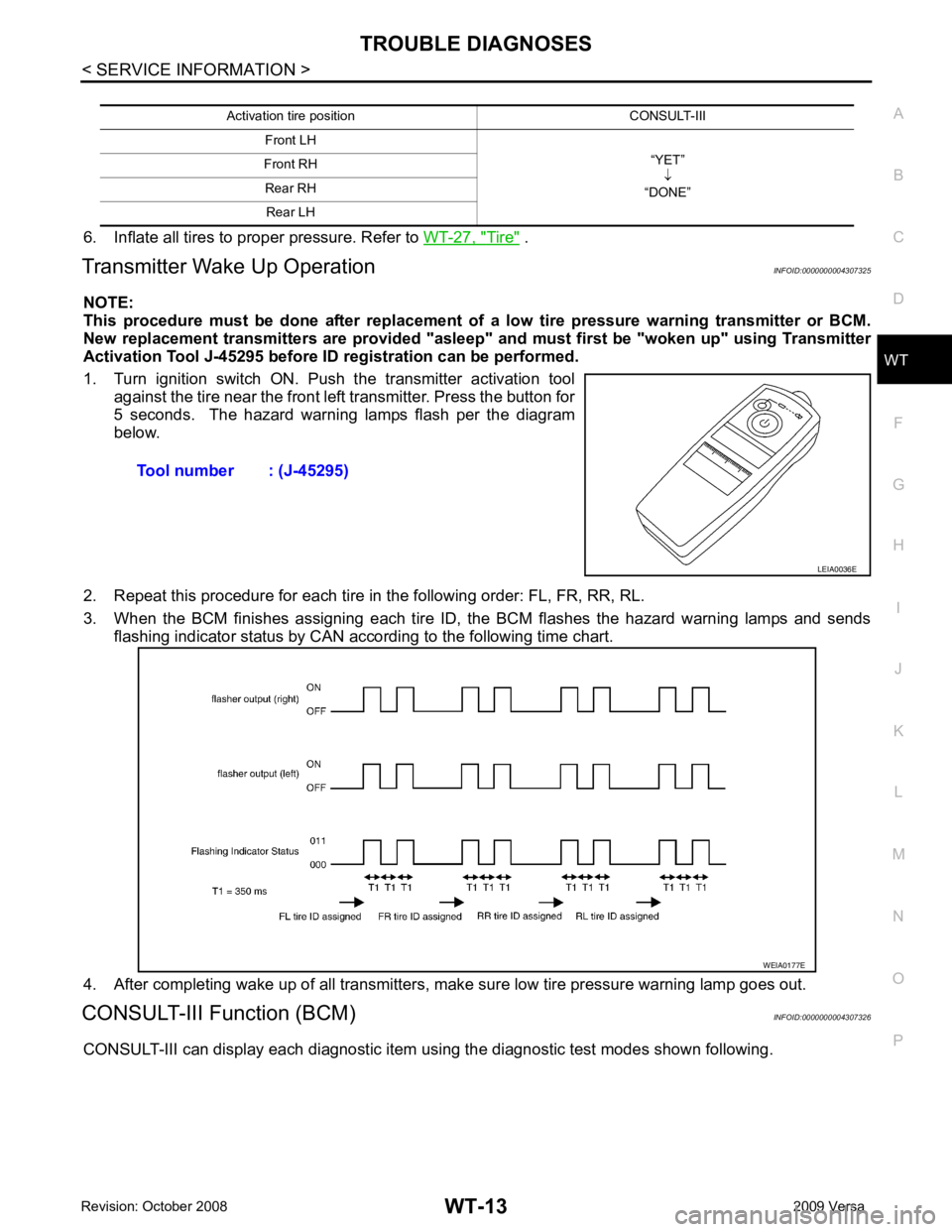
1. Turn ignition switch ON. Push the transmitter activation tool against the tire near the front left transmitter. Press the button for
5 seconds. The hazard warning lamps flash per the diagram
below.
2. Repeat this procedure for each tire in the following order: FL, FR, RR, RL.
3. When the BCM finishes assigning each tire ID, the BCM flashes the hazard warning lamps and sends flashing indicator status by CAN according to the following time chart.
4. After completing wake up of all transmitters, make sure low tire pressure warning lamp goes out.
CONSULT-III Function (BCM) INFOID:0000000004307326
CONSULT-III can display each diagnostic item using the diagnostic test modes shown following. Activation tire position CONSULT-III
Front LH “YET”↓
“DONE”
Front RH
Rear RH Rear LH Tool number : (J-45295)
LEIA0036E
WEIA0177E
Page 4280 of 4331
WT
N
O P
Preliminary Check
INFOID:0000000004307328
BASIC INSPECTION Tire " .
OK or NG OK >> GO TO 2.
NG >> Adjust tire pressure to specified value. YES >> GO TO 3.
NO >> GO TO WT-22, " Low Tire Pressure Warning Lamp Does Not Come On When Ignition Switch Is
Turned On " . Self-diagnosis :
WT-16 Trouble diagnosis for symptoms :
WT-22
Page 4282 of 4331

WT
N
O P
NOTE:
Before performing the self-diagnosis, be sure to register the ID or else the actual malfunction location may be different from that dis-
played on CONSULT-III.
Data Monitor Mode
NOTE:
Before performing the self-diagnosis, be sure to register the ID, or the actual malfunction location may be different from that displayed on
CONSULT-III.
Self-Diagnosis (Without CONSULT-III) INFOID:0000000004307330
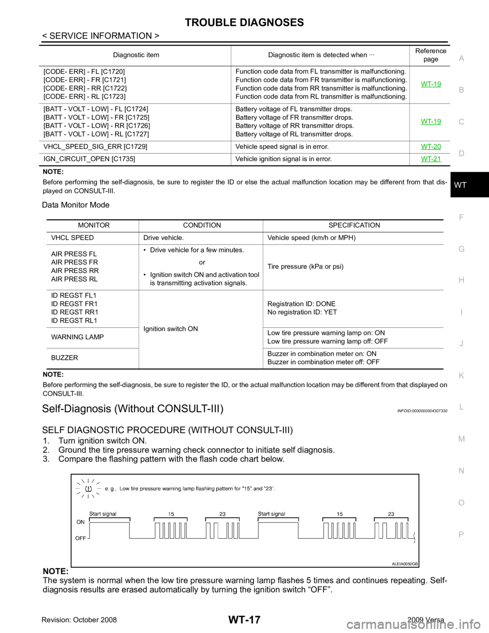
SELF DIAGNOSTIC PROCE DURE (WITHOUT CONSULT-III)
1. Turn ignition switch ON.
2. Ground the tire pressure warning check connector to initiate self diagnosis.
3. Compare the flashing pattern with the flash code chart below.
NOTE:
The system is normal when the low tire pressure warni ng lamp flashes 5 times and continues repeating. Self-
diagnosis results are erased automatically by turning the ignition switch “OFF”.
[CODE- ERR] - FL [C1720]
[CODE- ERR] - FR [C1721]
[CODE- ERR] - RR [C1722]
[CODE- ERR] - RL [C1723] Function code data from FL transmitter is malfunctioning.
Function code data from FR transmitter is malfunctioning.
Function code data from RR transmitter is malfunctioning.
Function code data from RL transmitter is malfunctioning. WT-19[BATT - VOLT - LOW] - FL [C1724]
[BATT - VOLT - LOW] - FR [C1725]
[BATT - VOLT - LOW] - RR [C1726]
[BATT - VOLT - LOW] - RL [C1727] Battery voltage of FL transmitter drops.
Battery voltage of FR transmitter drops.
Battery voltage of RR transmitter drops.
Battery voltage of RL transmitter drops. WT-19VHCL_SPEED_SIG_ERR [C1729] Vehicle
speed signal is in error.WT-20IGN_CIRCUIT_OPEN [C1735] Vehicle
ignition signal is in error. WT-21Diagnostic item Diagnostic item is detected when ···
Reference
page MONITOR CONDITION SPECIFICATION
VHCL SPEED Drive vehicle. Vehicle speed (km/h or MPH)
AIR PRESS FL
AIR PRESS FR
AIR PRESS RR
AIR PRESS RL • Drive vehicle for a few minutes.
Tire pressure (kPa or psi)
or
• Ignition switch ON and activation tool is transmitting activation signals.
ID REGST FL1
ID REGST FR1
ID REGST RR1
ID REGST RL1 Ignition switch ON Registration ID: DONE
No registration ID: YET
WARNING LAMP Low tire pressure
warning lamp on: ON
Low tire pressure warning lamp off: OFF
BUZZER Buzzer in combination meter on: ON
Buzzer in combination meter off: OFF
Page 4283 of 4331

System
Description " .
—
21
22
23
24 Transmitter no data (FL)
Transmitter no data (FR)
Transmitter no data (RR)
Transmitter no data (RL) WT-1931
32
33
34 Transmitter chec
ksum error (FL)
Transmitter chec ksum error (FR)
Transmitter chec ksum error (RR)
Transmitter chec ksum error (RL) WT-1935
36
37
38 Transmitter pressure
data error (FL)
Transmitter pressure data error (FR)
Transmitter pressure data error (RR)
Transmitter pressure data error (RL) WT-2041
42
43
44 Transmitter function
code error (FL)
Transmitter function code error (FR)
Transmitter function code error (RR)
Transmitter function code error (RL) WT-1945
46
47
48 Transmitter battery voltage low (FL)
Transmitter battery voltage low (FR)
Transmitter battery voltage low (RR)
Transmitter battery voltage low (RL) WT-1952 Vehicle speed signal
WT-2054 Vehicle ignition signal
WT-21Low tire pressure warning lamp does
not come on when ignition switch is
turned on. • Fuse or combination meter
• BCM connector or circuit
• BCM WT-22Low tire pressure
warning lamp stays
on when ignition switch is turned on. • Combination meter
• BCM connector or circuit
• BCM WT-22Low tire pressure wa
rning lamp flashes
when ignition switch is turned on. • BCM harness connector or circuit
• BCM
• Transmitter's mode off
• ID registration not completed yet WT-23Hazard warning lamps flash when igni-
tion switch is turned on. • BCM harness connector or circuit
• BCM WT-24ID registration cannot be completed.
• Transmitter
• Remote keyless entry receiver harness connector or circuit
• Remote keyless entry receiver
• BCM harness connector or circuit
• BCM WT-24
Page 4286 of 4331
WT
N
O P
Vehicle Ignition Signal
INFOID:0000000004307335
MALFUNCTION CODE NO. 54 (DTC C1735) Terminal and Reference Value for BCM " .
Are the inspection results normal with the ignition switch ON? YES >> GO TO 2.
NO >> Check CAN system. Refer to LAN-17, " Trouble Diagnosis Flow Chart " .
BCM Power Supply and Ground Circuit Inspec-
tion " .
Is the power supply with the ignition switch ON normal? YES >> GO TO 3.
NO >> Repair power supply as necessary. YES >> Inspection End.
NO >> Replace BCM. Refer to BCS-18, " Removal and Installation of BCM " .
Page 4287 of 4331
YES >> Malfunction in CAN communication system. GO TO
LAN-14, " CAN Diagnosis with CONSULT-
III " .
NO >> GO TO 2. Self-Diagnosis Mode of Combination Meter " .
Inspection results OK? OK >> GO TO 3.
NG >> Replace combination meter. Refer to IP-12, " Removal and Installation " .
YES >> Replace BCM. Refer to
BCS-18, " Removal and Installation of BCM " .
NO >> Check combination meter operation. Refer to DI-10, " Self-Diagnosis Mode of Combination
Meter " .
Low Tire Pressure Warning Lamp Stays On When Ignition Switch Is Turned On
INFOID:0000000004307337
DIAGNOSTIC PROCEDURE OK >> GO TO 2.
NG >> Repair or replace damaged parts. OK >> GO TO 3.
NG >> Check BCM power supply circuit for open or short.