2009 NISSAN LATIO service
[x] Cancel search: servicePage 3045 of 4331
![NISSAN LATIO 2009 Service Repair Manual EM-98< DISASSEMBLY AND ASSEMBLY >
[HR16DE]
CYLINDER BLOCK
2. Install water drain plug (1) to cylinder block as shown.
Use Genuine Silicone RTV Seal ant or equivalent. Refer to
GI-42, " Recomm NISSAN LATIO 2009 Service Repair Manual EM-98< DISASSEMBLY AND ASSEMBLY >
[HR16DE]
CYLINDER BLOCK
2. Install water drain plug (1) to cylinder block as shown.
Use Genuine Silicone RTV Seal ant or equivalent. Refer to
GI-42, " Recomm](/manual-img/5/57359/w960_57359-3044.png)
EM-98< DISASSEMBLY AND ASSEMBLY >
[HR16DE]
CYLINDER BLOCK
2. Install water drain plug (1) to cylinder block as shown.
Use Genuine Silicone RTV Seal ant or equivalent. Refer to
GI-42, " Recommended Chemical
Product and Sealant " .
3. Install main bearings and thrust bearings in their original positions with the following procedure:
a. Remove dust, dirt, and engine oil on the bearing mating surfaces of cylinder block.
b. Install thrust bearings to the both sides of the No. 3 journal hous- ing (B) on cylinder block.
• Install thrust bearings with the oil groove (A) facing crankshaft arm (outside).
c. Install the main bearings (1) paying attention to the direction. • Install the one with oil holes (A) onto cylinder block and the
one without oil holes onto main bearing cap.
• Before installing main bearings, apply new engine oil to the bearing surface (inside). Do not apply engine oil to the back
surface, but thoroughly clean it.
• Ensure the oil holes on cylinder block and those on the corre- sponding bearing are aligned.
• Install the main bearing in the position shown.
NOTE:
Install the main bearing in the center position with the following
dimension. For service operati on, the center position can be
checked visually. : Engine front PBIC3742E
: Engine front
PBIC3258J
PBIC3746E
1 : Cylinder block
2 : Main bearing (upper)
3 : Main bearing (lower)
4 : Main bearing cap
: Engine front PBIC3747E
Journal position No. 1 No. 2 No. 3 No. 4 No. 5
L1 [Unit: mm (in)] 1.65–2.05 1.25–1.65 2.30–2.70 1.25–1.65 1.60–2.00
(0.065-0.081) (0.049-0.065) (0.091-0.106) (0.049-0.065) (0.063-0.079)
L2 [Unit: mm (in)] 1.30–1.70 1.30–1.70 2.30–2.70 1.30–1.70 1.30–1.70
(0.051-0.067) (0.051-0.067) (0.091-0.106) (0.051-0.067) (0.051-0.067)
Page 3048 of 4331

EM
NP
O
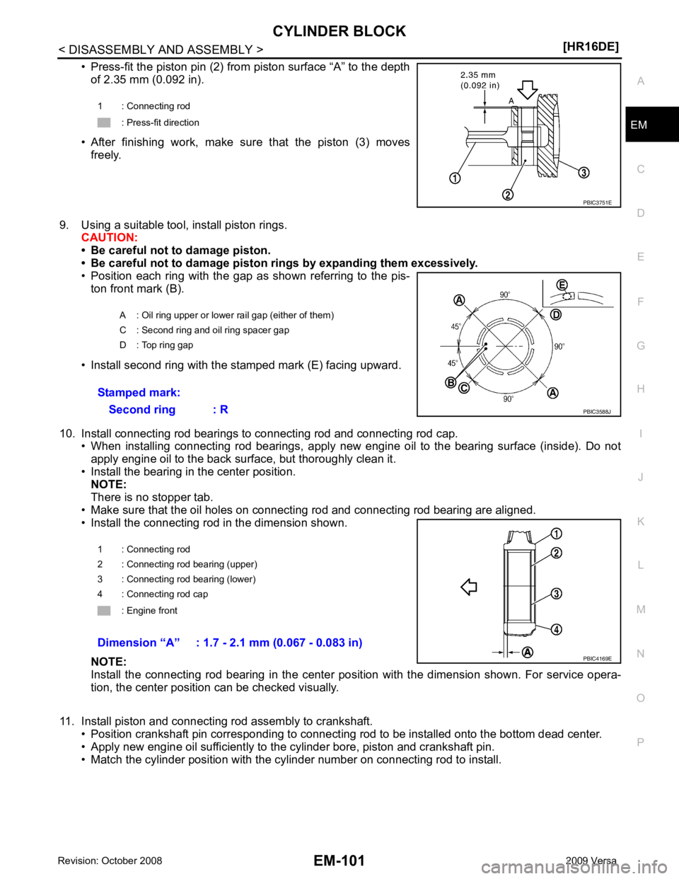
• Press-fit the piston pin (2) from piston surface “A” to the depth
of 2.35 mm (0.092 in).
• After finishing work, make sure that the piston (3) moves freely.
9. Using a suitable tool, install piston rings. CAUTION:
• Be careful not to damage piston.
• Be careful not to damage piston rings by expanding them excessively.
• Position each ring with the gap as shown referring to the pis-
ton front mark (B).
• Install second ring with the stamped mark (E) facing upward.
10. Install connecting rod bearings to connecting rod and connecting rod cap. • When installing connecting rod bearings, apply new engine oil to the bearing surface (inside). Do not
apply engine oil to the back surface, but thoroughly clean it.
• Install the bearing in the center position. NOTE:
There is no stopper tab.
• Make sure that the oil holes on connecting rod and connecting rod bearing are aligned.
• Install the connecting rod in the dimension shown.
NOTE:
Install the connecting rod bearing in the center pos ition with the dimension shown. For service opera-
tion, the center position can be checked visually.
11. Install piston and connecting rod assembly to crankshaft. • Position crankshaft pin corres ponding to connecting rod to be installed onto the bottom dead center.
• Apply new engine oil sufficiently to the cylinder bore, piston and crankshaft pin.
• Match the cylinder position with the cy linder number on connecting rod to install.
1 : Connecting rod
: Press-fit direction
Page 3054 of 4331

EM
NP
O
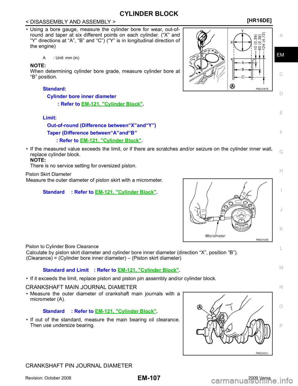
• Using a bore gauge, measure the cylinder bore for wear, out-of-
round and taper at six different points on each cylinder. (“X” and
“Y” directions at “A”, “B” and “C”) (“Y” is in longitudinal direction of
the engine)
NOTE:
When determining cylinder bore grade, measure cylinder bore at
“B” position.
• If the measured value exceeds the limit, or if there are scratches and/or seizure on the cylinder inner wall,
replace cylinder block.
NOTE:
There is no service setting for oversized piston.
Piston Skirt Diameter Measure the outer diameter of piston skirt with a micrometer.
Piston to Cylinder Bore Clearance Calculate by piston skirt diameter and cylinder bor e inner diameter (direction “X”, position “B”).
(Clearance) = (Cylinder bore inner di ameter) – (Piston skirt diameter)
• If it exceeds the limit, replace piston and piston pin assembly and/or cylinder block.
CRANKSHAFT MAIN JOURNAL DIAMETER • Measure the outer diameter of crankshaft main journals with a micrometer (A).
• If out of the standard, measure the main bearing oil clearance. Then use undersize bearing.
CRANKSHAFT PIN JOURNAL DIAMETER A : Unit: mm (in)
Standard: Cylinder bore inner diameter : Refer to EM-121, " Cylinder Block " .
Limit: Out-of-round (Difference between“X”and“Y”)
Taper (Difference between“A”and“B” : Refer to EM-121, " Cylinder Block " .
Cylinder Block " .
Cylinder Block " .
Standard : Refer to EM-121, " Cylinder Block " .
Page 3058 of 4331

EM
NP
O
HOW TO SELECT PISTON AND BEARING
Description INFOID:0000000004784319
• The identification grade stamped on each part is the grade for the dimension measured in new condition.
This grade cannot apply to reused parts.
• For reused or repaired parts, measure the dimens ion accurately. Determine the grade by comparing the
measurement with the values of each selection table.
• For details of the measurement method of each part , the reuse standards and the selection method of the
selective fitting parts, follow the procedures.
Connecting Rod Bearing INFOID:0000000004784320
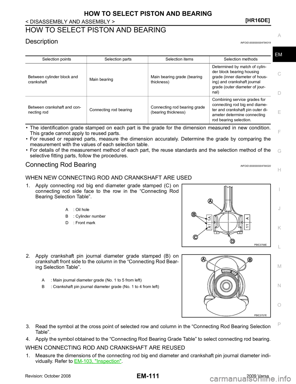
WHEN NEW CONNECTING ROD AND CRANKSHAFT ARE USED 1. Apply connecting rod big end diameter grade stamped (C) on connecting rod side face to the row in the “Connecting Rod
Bearing Selection Table”.
2. Apply crankshaft pin journal diameter grade stamped (B) on crankshaft front side to the column in the “Connecting Rod Bear-
ing Selection Table”.
3. Read the symbol at the cross point of selected ro w and column in the “Connecting Rod Bearing Selection
Table”.
4. Apply the symbol obtained to the “Connecting Rod Bear ing Grade Table” to select connecting rod bearing.
WHEN CONNECTING ROD AND CRANKSHAFT ARE REUSED 1. Measure the dimensions of the connecting rod big end diameter and crankshaft pin journal diameter indi-
vidually. Refer to EM-103, " Inspection " .
Selection points Selection parts Selection items Selection methods
Between cylinder block and
crankshaft Main bearing Main bearing grade (bearing
thickness) Determined by match of cylin-
der block bearing housing
grade (inner diameter of hous-
ing) and crankshaft journal
grade (outer diameter of jour-
nal)
Between crankshaft and con-
necting rod Connecting rod bearing Connecting rod bearing grade
(bearing thickness) Combining service grades for
connecting rod big end diame-
ter and crankshaft pin outer di-
ameter determine connecting
rod bearing selection. A : Oil hole
B : Cylinder number
D : Front mark
Page 3060 of 4331
![NISSAN LATIO 2009 Service Repair Manual HOW TO SELECT PISTON AND BEARING
EM-113
< DISASSEMBLY AND ASSEMBLY >
[HR16DE] C
D E
F
G H
I
J
K L
M A EM
NP
O
In grinding crankshaft pin to
use undersize bearings, keep the
fillet R (A) [0.8 NISSAN LATIO 2009 Service Repair Manual HOW TO SELECT PISTON AND BEARING
EM-113
< DISASSEMBLY AND ASSEMBLY >
[HR16DE] C
D E
F
G H
I
J
K L
M A EM
NP
O
In grinding crankshaft pin to
use undersize bearings, keep the
fillet R (A) [0.8](/manual-img/5/57359/w960_57359-3059.png)
HOW TO SELECT PISTON AND BEARING
EM-113
< DISASSEMBLY AND ASSEMBLY >
[HR16DE] C
D E
F
G H
I
J
K L
M A EM
NP
O
In grinding crankshaft pin to
use undersize bearings, keep the
fillet R (A) [0.8 - 1.2 mm (0.031 - 0.047 in)].
Main Bearing INFOID:0000000004784321
HOW TO SELECT MAIN BEARING
When New Cylinder Block and Crankshaft Are Used
1. “Main Bearing Selection Table” rows correspond to main bearing housing grade on left side of cylinder block.
• If there is a corrected stamp mark (B) on cylinder block, use it as a correct reference.
2. Apply main journal diameter grade stamped on crankshaft front side to column in the “Main Bearing Selection Table”.
3. Read the symbol at the cross point of selected row and column in the “Main Bearing Selection Table”.
4. Apply the symbol obtained to the “Main B earing Grade Table” to select main bearing.
NOTE:
Service part is available as a set of both upper and lower.
When Cylinder Block and Crankshaft Are Reused 1. Measure the dimensions of the cylinder block ma in bearing housing inner diameter and crankshaft main
journal diameter individually. Refer to EM-103, " Inspection " .
2. Apply the measured dimension to t he “Main Bearing Selection Table”.
3. Read the symbol at the cross point of selected row and column in the “Main Bearing Selection Table”.
4. Apply the symbol obtained to the “Main B earing Grade Table” to select main bearing.
Bearing undersize table:
Refer to EM-124, " Connecting Rod Bearing " .
PBIC3263J
A : Basic stamp mark
: Engine front PBIC3760E
A : Main journal diameter grade (No. 1 to 5 from left)
B : Crankshaft pin journal diameter grade (No. 1 to 4 from left) PBIC3757E
Page 3067 of 4331
![NISSAN LATIO 2009 Service Repair Manual Items
Standard Oversize (service) [0.2 (0.008)]
Valve guide Outer diameter 9.023 - 9.034 (0.3552 - 0.3557) 9.223 - 9.234 (0.3631 - 0.3635)
Inner diameter (Finished size) 5.000 - 5.018 (0.1969 - 0.197 NISSAN LATIO 2009 Service Repair Manual Items
Standard Oversize (service) [0.2 (0.008)]
Valve guide Outer diameter 9.023 - 9.034 (0.3552 - 0.3557) 9.223 - 9.234 (0.3631 - 0.3635)
Inner diameter (Finished size) 5.000 - 5.018 (0.1969 - 0.197](/manual-img/5/57359/w960_57359-3066.png)
Items
Standard Oversize (service) [0.2 (0.008)]
Valve guide Outer diameter 9.023 - 9.034 (0.3552 - 0.3557) 9.223 - 9.234 (0.3631 - 0.3635)
Inner diameter (Finished size) 5.000 - 5.018 (0.1969 - 0.1976)
Cylinder head valve guide hole diameter 8.975 - 8.996 (0.3533 - 0.3542) 9.175 - 9.196 (0.3612 - 0.3620)
Interference fit of valve guide 0.027 - 0.059 (0.0011 - 0.0023)
Items Standard Limit
Valve guide clearance Intake 0.020 - 0.053 (0.0008 - 0.0021)
0.1 (0.004)
Exhaust 0.030 - 0.063 (0.0012 - 0.0025)
Projection length “H” 11.4 - 11.8 (0.449 - 0.465)
Page 3070 of 4331
![NISSAN LATIO 2009 Service Repair Manual SERVICE DATA AND SPECIFICATIONS (SDS)
EM-123
< SERVICE DATA AND SPECIFICATIONS (SDS)
[HR16DE] C
D E
F
G H
I
J
K L
M A EM
NP
O
Unit: mm (in)
CONNECTING ROD Unit: mm (in)
CRANKSHAFT Unit: mm (in)
Pisto NISSAN LATIO 2009 Service Repair Manual SERVICE DATA AND SPECIFICATIONS (SDS)
EM-123
< SERVICE DATA AND SPECIFICATIONS (SDS)
[HR16DE] C
D E
F
G H
I
J
K L
M A EM
NP
O
Unit: mm (in)
CONNECTING ROD Unit: mm (in)
CRANKSHAFT Unit: mm (in)
Pisto](/manual-img/5/57359/w960_57359-3069.png)
SERVICE DATA AND SPECIFICATIONS (SDS)
EM-123
< SERVICE DATA AND SPECIFICATIONS (SDS)
[HR16DE] C
D E
F
G H
I
J
K L
M A EM
NP
O
Unit: mm (in)
CONNECTING ROD Unit: mm (in)
CRANKSHAFT Unit: mm (in)
Piston pin outer diameter 18.996 - 19.002 (0.7479 - 0.7481)
Piston to piston pin oil clearance Standard 0.008 - 0.012 (0.0003 - 0.0005) Center distance
129.84 - 129.94 (5.11 - 5.12)
Bend [per 100 (3.94)] Limit 0.15 (0.0059)
Torsion [per 100 (3.94)] Limit 0.30 (0.0118)
Connecting rod small end clearance Standard –0.018 - –0.044 (–0.0007 - –0.0017)
Connecting rod small end inner diameter Standard 18.958 - 18.978 (0.7464 - 0.7472)
Connecting rod side clearance Standard 0.200 - 0.352 (0.0079 - 0.0139)
Connecting rod big end diameter Grade No. A
Grade No. B
Grade No. C
Grade No. D
Grade No. E
Grade No. F
Grade No. G
Grade No. H
Grade No. J
Grade No. K
Grade No. L
Grade No. M
Grade No. N 43.000 - 43.001 (1.6929 - 1.6929)
43.001 - 43.002 (1.6929 - 1.6930)
43.002 - 43.003 (1.6930 - 1.6930)
43.003 - 43.004 (1 6930 - 1.6931)
43.004 - 43.005 (1.6931 - 1.6931)
43.005 - 43.006 (1.6931 - 1.6931)
43.006 - 43.007 (1.6931 - 1.6932)
43.007 - 43.008 (1.6932 - 1.6932)
43.008 - 43.009 (1.6932 - 1.6933)
43.009 - 43.010 (1.6933 - 1.6933) 43.010 - 43.011 (1.6933 - 1.6933)
43.011 - 43.012 (1.6933 - 1.6934)
43.012 - 43.013 (1.6934 - 1.6934) Center distance “r”
41.68 - 41.76 (1.6409 - 1.6441)
Out-of-round Limit 0.003 (0.0001)
Taper Limit 0.004 (0.0002)
Runout [TIR*] Limit 0.10 (0.0039)
Crankshaft end play Standard 0.098 - 0.260 (0.0039 - 0.0102)
Limit 0.35 (0.0138) SEM645 PBIC3459J
Page 3074 of 4331
![NISSAN LATIO 2009 Service Repair Manual PRECAUTIONS
EM-127
< SERVICE INFORMATION >
[MR18DE] C
D E
F
G H
I
J
K L
M A EM
NP
O
5. When the repair work is completed, return the ignition switch to the
″LOCK ″ position before c NISSAN LATIO 2009 Service Repair Manual PRECAUTIONS
EM-127
< SERVICE INFORMATION >
[MR18DE] C
D E
F
G H
I
J
K L
M A EM
NP
O
5. When the repair work is completed, return the ignition switch to the
″LOCK ″ position before c](/manual-img/5/57359/w960_57359-3073.png)
PRECAUTIONS
EM-127
< SERVICE INFORMATION >
[MR18DE] C
D E
F
G H
I
J
K L
M A EM
NP
O
5. When the repair work is completed, return the ignition switch to the
″LOCK ″ position before connecting
the battery cables. (At this time, the steering lock mechanism will engage.)
6. Perform a self-diagnosis check of al l control units using CONSULT-III.
Precaution for Procedur e without Cowl Top Cover INFOID:0000000004307110
When performing the procedure after removing cowl top cover, cover
the lower end of windshield.
Precaution for Drain Coolant INFOID:0000000004307112
• Drain coolant when engine is cooled.
Precaution for Disco nnecting Fuel Piping INFOID:0000000004307113
• Before starting work, make sure no fire or spark producing items are in the work area.
• Release fuel pressure before disassembly.
• After disconnecting pipes, plug openings to stop fuel leakage.
Precaution for Removal and Disassembly INFOID:0000000004307114
• When instructed to use special service tools, use the spec ified tools. Always be careful to work safely, avoid
forceful or uninstructed operations.
• Exercise maximum care to avoid damage to mating or sliding surfaces.
• Cover openings of engine system with tape or the equiva lent, if necessary, to seal out foreign materials.
• Mark and arrange disassembly parts in an organized way for easy troubleshooting and assembly.
• When loosening nuts and bolts, as a basic rule, start with the one furthest outside, then the one diagonally opposite, and so on. If the order of loosening is specif ied, do exactly as specified. Power tools may be used
where noted in the step.
Precaution for Inspection, Repair and Replacement INFOID:0000000004307115
• Before repairing or replacing, thoroughly inspect parts. Inspect new replacement parts in the same way, and
replace if necessary.
Precaution for Assembly and Installation INFOID:0000000004307116
• Use torque wrench to tighten bolts or nuts to specification.
• When tightening nuts and bolts, as a basic rule, equally tighten in several different steps starting with the ones in center, then ones on inside and outside diagonally in this order. If the order of tightening is specified,
do exactly as specified.
• Replace with new gasket, packing, oil seal or O-ring.
• Thoroughly wash, clean, and air-blow each part. Carefully check oil or coolant passages for any restriction
and blockage.
• Avoid damaging sliding or mating surfaces. Completely remove foreign materials such as cloth lint or dust. Before assembly, oil sliding surfaces well.
• Release air within route after draining coolant.
• Before starting engine, apply fuel pressure to fuel lines with turning ignition switch ON (with engine stopped). Then make sure that there are no leaks at fuel line connections.
• After repairing, start engine and increase engine speed to check coolant, fuel, oil, and exhaust systems for leakage. PIIB3706J