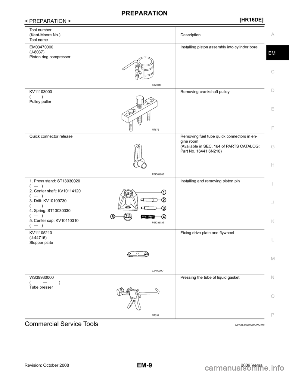
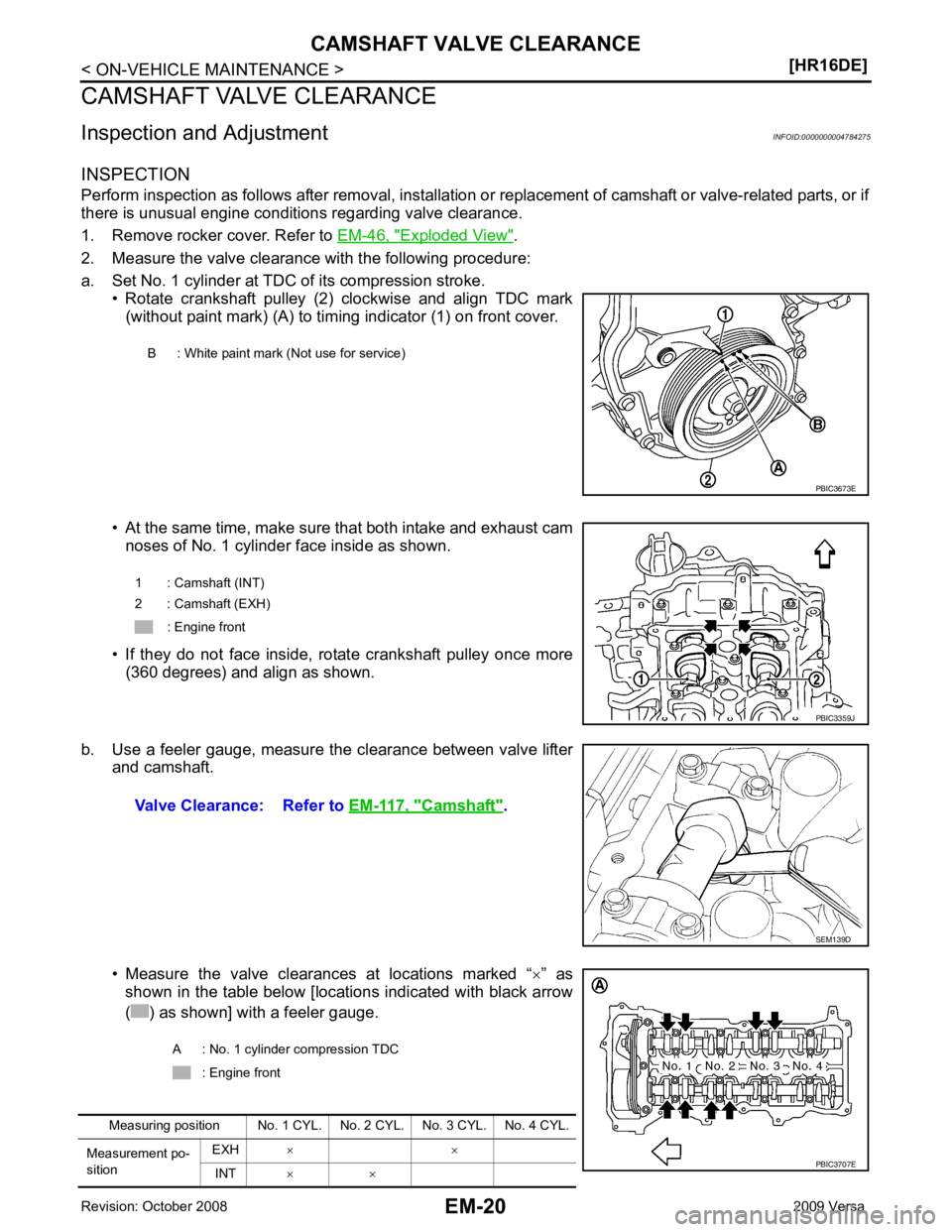
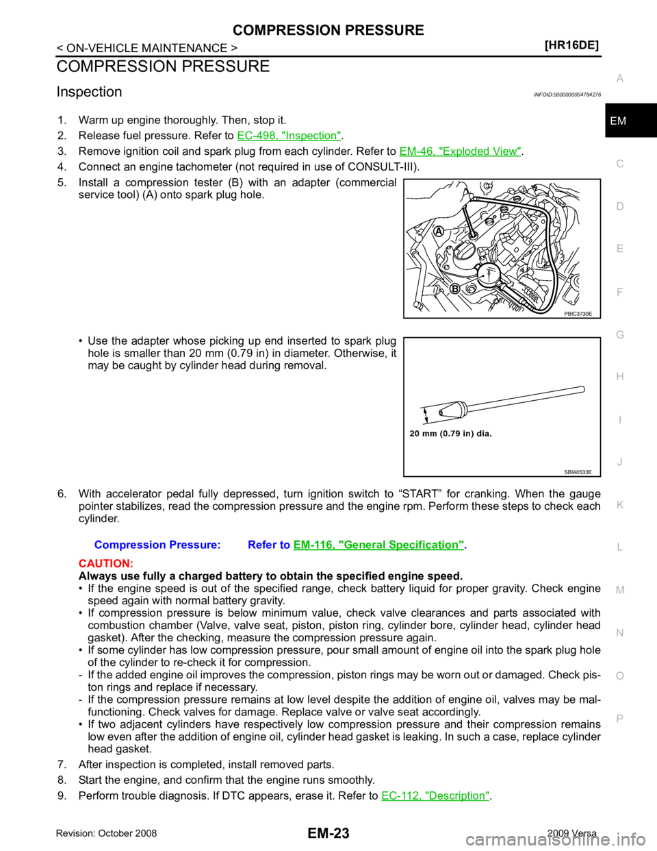
2009 NISSAN LATIO service
[x] Cancel search: servicePage 2952 of 4331
![NISSAN LATIO 2009 Service Repair Manual PRECAUTIONS
EM-5
< PRECAUTION >
[HR16DE] C
D E
F
G H
I
J
K L
M A EM
NP
O
5. When the repair work is completed, return the ignition switch to the
″LOCK ″ position before connecting
t NISSAN LATIO 2009 Service Repair Manual PRECAUTIONS
EM-5
< PRECAUTION >
[HR16DE] C
D E
F
G H
I
J
K L
M A EM
NP
O
5. When the repair work is completed, return the ignition switch to the
″LOCK ″ position before connecting
t](/manual-img/5/57359/w960_57359-2951.png)
PRECAUTIONS
EM-5
< PRECAUTION >
[HR16DE] C
D E
F
G H
I
J
K L
M A EM
NP
O
5. When the repair work is completed, return the ignition switch to the
″LOCK ″ position before connecting
the battery cables. (At this time, the steering lock mechanism will engage.)
6. Perform a self-diagnosis check of al l control units using CONSULT-III.
Precaution for Procedur e without Cowl Top Cover INFOID:0000000004784258
When performing the procedure after removing cowl top cover, cover
the lower end of windshield.
Precaution for Drain Coolant INFOID:0000000004784260
• Drain coolant when engine is cooled.
Precaution for Disco nnecting Fuel Piping INFOID:0000000004784261
• Before starting work, make sure no fire or spark producing items are in the work area.
• Release fuel pressure before disassembly.
• After disconnecting pipes, plug openings to stop fuel leakage.
Precaution for Removal and Disassembly INFOID:0000000004784262
• When instructed to use special service tools, use the spec ified tools. Always be careful to work safely, avoid
forceful or uninstructed operations.
• Exercise maximum care to avoid damage to mating or sliding surfaces.
• Cover openings of engine system with tape or the equiva lent, if necessary, to seal out foreign materials.
• Mark and arrange disassembly parts in an organized way for easy troubleshooting and assembly.
• When loosening nuts and bolts, as a basic rule, start with the one furthest outside, then the one diagonally opposite, and so on. If the order of loosening is specif ied, do exactly as specified. Power tools may be used
where noted in the step.
Precaution for Inspection, Repair and Replacement INFOID:0000000004784263
• Before repairing or replacing, thoroughly inspect parts. Inspect new replacement parts in the same way, and
replace if necessary.
Precaution for Assembly and Installation INFOID:0000000004784264
• Use torque wrench to tighten bolts or nuts to specification.
• When tightening nuts and bolts, as a basic rule, equally tighten in several different steps starting with the ones in center, then ones on inside and outside diagonally in this order. If the order of tightening is specified,
do exactly as specified.
• Replace with new gasket, packing, oil seal or O-ring.
• Thoroughly wash, clean, and air-blow each part. Carefully check oil or coolant passages for any restriction
and blockage.
• Avoid damaging sliding or mating surfaces. Completely remove foreign materials such as cloth lint or dust. Before assembly, oil sliding surfaces well.
• Release air within route after draining coolant.
• Before starting engine, apply fuel pressure to fuel lines with turning ignition switch ON (with engine stopped). Then make sure that there are no leaks at fuel line connections.
• After repairing, start engine and increase engine speed to check coolant, fuel, oil, and exhaust systems for leakage. PIIB3706J
Page 2956 of 4331

EM
NP
O
Commercial Service Tools INFOID:0000000004784268
EM03470000
(J-8037)
Piston ring compressor Installing piston assembly into cylinder bore
KV11103000
( — )
Pulley puller Removing crankshaft pulley
Quick connector release Removing fuel tube quick connectors in en- gine room
(Available in SEC. 164 of PARTS CATALOG:
Part No. 16441 6N210)
1. Press stand: ST13030020
( — )
2. Center shaft: KV10114120
( — )
3. Drift: KV10109730
( — )
4. Spring: ST13030030
( — )
5. Center cap: KV10110310
( — ) Installing and removing piston pin
KV11105210
(J-44716)
Stopper plate Fixing drive plate and flywheel
WS39930000
( — )
Tube presser Pressing the tube of liquid gasket
Tool number
(Kent-Moore No.)
Tool name Description PBIC0198E
PBIC3873E
ZZA0009D
NT052
Page 2967 of 4331

Exploded View " .
2. Measure the valve clearance with the following procedure:
a. Set No. 1 cylinder at TDC of its compression stroke. • Rotate crankshaft pulley (2) clockwise and align TDC mark(without paint mark) (A) to timing indicator (1) on front cover.
• At the same time, make sure that both intake and exhaust cam noses of No. 1 cylinder face inside as shown.
• If they do not face inside, rotate crankshaft pulley once more (360 degrees) and align as shown.
b. Use a feeler gauge, measure the clearance between valve lifter and camshaft.
• Measure the valve clearances at locations marked “ ×” as
shown in the table below [locations indicated with black arrow
( ) as shown] with a feeler gauge. B : White paint mark (Not use for service)
Camshaft " .
Page 2968 of 4331
![NISSAN LATIO 2009 Service Repair Manual CAMSHAFT VALVE CLEARANCE
EM-21
< ON-VEHICLE MAINTENANCE >
[HR16DE] C
D E
F
G H
I
J
K L
M A EM
NP
O
c. Rotate crankshaft pulley (2) one revolution (360 degrees) and
align TDC mark (without pain NISSAN LATIO 2009 Service Repair Manual CAMSHAFT VALVE CLEARANCE
EM-21
< ON-VEHICLE MAINTENANCE >
[HR16DE] C
D E
F
G H
I
J
K L
M A EM
NP
O
c. Rotate crankshaft pulley (2) one revolution (360 degrees) and
align TDC mark (without pain](/manual-img/5/57359/w960_57359-2967.png)
CAMSHAFT VALVE CLEARANCE
EM-21
< ON-VEHICLE MAINTENANCE >
[HR16DE] C
D E
F
G H
I
J
K L
M A EM
NP
O
c. Rotate crankshaft pulley (2) one revolution (360 degrees) and
align TDC mark (without paint mark) (A) to timing indicator (1) on
front cover.
• Measure the valve clearance at locations marked “ ×” as shown
in the table below [locations indicated with black arrow ( ) as
shown] with a feeler gauge.
3. If out of standard, perform adjustment procedure.
ADJUSTMENT • Perform adjustment depending on selected head thickness of valve lifter.
1. Remove camshaft. Refer to EM-58, " Exploded View " .
2. Remove valve lifters at the loca tions that are out of the standard.
3. Measure the center thickness of the removed valve lifters with a micrometer (A).
4. Use the equation below to calculate valve lifter thickness for replacement. B : White paint mark (Not use for service) PBIC3673E
A : No. 4 cylinder compression TDC
: Engine front
Measuring position No. 1 CYL. No . 2 CYL. No. 3 CYL. No. 4 CYL.
Measurement
point EXH
× ×
INT × × PBIC3708E
PBIC3195J
Valve lifter thickness calculation: t = t
1 + (C 1– C 2)
t = Valve lifter thickness to be replaced
t 1
= Removed valve lifter thickness
C 1
= Measured valve clearance
C 2
= Standard valve clearance:
Intake : 0.30 mm (0.012 in)
Exhaust : 0.33 mm (0.013 in)
Page 2970 of 4331

EM
NP
O
COMPRESSION PRESSURE
Inspection INFOID:0000000004784276
1. Warm up engine thoroughly. Then, stop it.
2. Release fuel pressure. Refer to EC-498, " Inspection " .
3. Remove ignition coil and spark plug from each cylinder. Refer to EM-46, " Exploded View " .
4. Connect an engine tachometer (not required in use of CONSULT-III).
5. Install a compression tester (B) with an adapter (commercial service tool) (A) onto spark plug hole.
• Use the adapter whose picking up end inserted to spark plug hole is smaller than 20 mm (0.79 in) in diameter. Otherwise, it
may be caught by cylinder head during removal.
6. With accelerator pedal fully depressed, turn ignition switch to “START” for cranking. When the gauge pointer stabilizes, read the compression pressure and the engine rpm. Perform these steps to check each
cylinder.
CAUTION:
Always use fully a charged battery to obtain the specified engine speed.
• If the engine speed is out of the specified range, c heck battery liquid for proper gravity. Check engine
speed again with normal battery gravity.
• If compression pressure is below minimum value, check valve clearances and parts associated with combustion chamber (Valve, valve seat, piston, pi ston ring, cylinder bore, cylinder head, cylinder head
gasket). After the checking, measure the compression pressure again.
• If some cylinder has low compression pressure, pour small amount of engine oil into the spark plug hole
of the cylinder to re-check it for compression.
- If the added engine oil improves the compression, piston rings may be worn out or damaged. Check pis-
ton rings and replace if necessary.
- If the compression pressure remains at low level despite the addition of engine oil, valves may be mal- functioning. Check valves for damage. Replace valve or valve seat accordingly.
• If two adjacent cylinders have respectively low compression pressure and their compression remains low even after the addition of engine oil, cylinder head gasket is leaking. In such a case, replace cylinder
head gasket.
7. After inspection is completed, install removed parts.
8. Start the engine, and confirm that the engine runs smoothly.
9. Perform trouble diagnosis. If DTC appears, erase it. Refer to EC-112, " Description " . SBIA0533E
General Specification " .
Page 2997 of 4331
![NISSAN LATIO 2009 Service Repair Manual EM-50< ON-VEHICLE REPAIR >
[HR16DE]
TIMING CHAIN
4. Remove the following parts. • Intake manifold: Refer to EM-28, " Exploded View " .
• Drive belt: Refer to EM-15, " Removal and Installation " NISSAN LATIO 2009 Service Repair Manual EM-50< ON-VEHICLE REPAIR >
[HR16DE]
TIMING CHAIN
4. Remove the following parts. • Intake manifold: Refer to EM-28, " Exploded View " .
• Drive belt: Refer to EM-15, " Removal and Installation "](/manual-img/5/57359/w960_57359-2996.png)
EM-50< ON-VEHICLE REPAIR >
[HR16DE]
TIMING CHAIN
4. Remove the following parts. • Intake manifold: Refer to EM-28, " Exploded View " .
• Drive belt: Refer to EM-15, " Removal and Installation " .
• Water pump pulley: Refer to CO-20, " Exploded View " .
• Ground cable (RH)
5. Support the bottom surface of engine using a tr ansmission jack, and then remove the engine mounting
bracket and insulator (RH). Refer to EM-88, " Exploded View " .
6. Remove rocker cover. Refer to EM-46, " Exploded View " .
7. Set No. 1 cylinder at TDC of its compression stroke with the following procedure:
a. Rotate crankshaft pulley (2) clockwise and align TDC mark (without paint mark) (A) to timing indicator (1) on front cover.
b. Make sure the matching marks on each camshaft sprocket are positioned as shown.
• If not, rotate crankshaft pulley one more turn to align matching marks to the positions.
8. Remove crankshaft pulley with the following procedure:
a. Secure crankshaft pulley (1) using a suitable tool (A).
b. Loosen and pull out crankshaft pulley bolts. CAUTION:
Never remove the bolts as they are used as a supporting
point for the pulley puller.
c. Attach Tool (A) in the M 6 thread hole on crankshaft pulley, and remove crankshaft pulley. B : White paint mark (Not use for service) PBIC3673E
1 : Camshaft sprocket (EXH)
2 : Camshaft sprocket (INT)
A : Matching mark (stamp)
B : Matching mark (peripheral stamp line) PBIC3872E
PBIC3710E
B : M6 bolt
Tool number : KV11103000 ( — ) PBIC3711E
Page 3006 of 4331
![NISSAN LATIO 2009 Service Repair Manual CAMSHAFT
EM-59
< ON-VEHICLE REPAIR >
[HR16DE] C
D E
F
G H
I
J
K L
M A EM
NP
O
5. Support the bottom surface of engine using a trans
mission jack, and then remove the engine mounting
bra NISSAN LATIO 2009 Service Repair Manual CAMSHAFT
EM-59
< ON-VEHICLE REPAIR >
[HR16DE] C
D E
F
G H
I
J
K L
M A EM
NP
O
5. Support the bottom surface of engine using a trans
mission jack, and then remove the engine mounting
bra](/manual-img/5/57359/w960_57359-3005.png)
CAMSHAFT
EM-59
< ON-VEHICLE REPAIR >
[HR16DE] C
D E
F
G H
I
J
K L
M A EM
NP
O
5. Support the bottom surface of engine using a trans
mission jack, and then remove the engine mounting
bracket and insulator (RH). Refer to EM-88, " Exploded View " .
6. Remove rocker cover. Refer to EM-46, " Exploded View " .
7. Set No. 1 cylinder at TDC of its comp ression stroke with the following procedure:
a. Rotate crankshaft pulley (2) clockwise and align TDC mark (without paint mark) (A) to timing indicator (1) on front cover.
b. Make sure the matching marks on each camshaft sprocket are positioned as shown.
• If not, rotate crankshaft pulley one more turn to align matching marks to the positions.
8. Remove crankshaft pulley with the following procedure:
a. Secure crankshaft pulley (1) using a suitable tool (A).
b. Loosen and pull out crankshaft pulley bolts. CAUTION:
Never remove the bolts as they are used as a supporting
point for the pulley puller.
c. Attach Tool (A) in the M 6 thread hole on crankshaft pulley, and remove crankshaft pulley.
9. Remove front cover with the following procedure: B : White paint mark (Not use for service) PBIC3673E
1 : Camshaft sprocket (EXH)
2 : Camshaft sprocket (INT)
A : Matching mark (stamp)
B : Matching mark (peripheral stamp line) PBIC3872E
PBIC3710E
B : M6 bolt
Tool number : KV11103000 ( — ) PBIC3711E
Page 3033 of 4331
![NISSAN LATIO 2009 Service Repair Manual EM-86< ON-VEHICLE REPAIR >
[HR16DE]
CYLINDER HEAD
c. Using suitable tool, press valve guide (1) from camshaft side to the dimensions as shown.
WARNING:
Cylinder head (2) contains h eat. Wear protectiv NISSAN LATIO 2009 Service Repair Manual EM-86< ON-VEHICLE REPAIR >
[HR16DE]
CYLINDER HEAD
c. Using suitable tool, press valve guide (1) from camshaft side to the dimensions as shown.
WARNING:
Cylinder head (2) contains h eat. Wear protectiv](/manual-img/5/57359/w960_57359-3032.png)
EM-86< ON-VEHICLE REPAIR >
[HR16DE]
CYLINDER HEAD
c. Using suitable tool, press valve guide (1) from camshaft side to the dimensions as shown.
WARNING:
Cylinder head (2) contains h eat. Wear protective equipment
to avoid getting burned.
d. Using suitable tool (A), apply reamer finish to valve guide.
2. Install the valve seat, if necessary. CAUTION:
Replace with oversize [0.5 mm (0.020 in)] valve seat.
a. Ream cylinder head recess diameter (a) for service valve seat.
• Be sure to ream in circles concentric to valve guide center.This will enable valve to fit correctly.
b. Heat cylinder head to 110 to 130 °C (230 to 266 °F) by soaking in
heated oil (A).
c. Provide valve seats cooled well with dry ice. Force fit valve seat into cylinder head. WARNING:
• Cylinder head contains heat. Wear prot ective equipment to avoid getting burned.
• Avoid directly touching cold valve seats. Projection “H”: Refer to
EM-119, " Cylinder Head " .
PBIC3217J
Standard: Refer to
EM-119, " Cylinder Head " .
PBIC3215J
For service parts: Oversize [0.5 mm (0.020 in)]
Refer to EM-119, " Cylinder Head " .
JPBIA0188ZZ
PBIC3214J