2009 MITSUBISHI ASX warning
[x] Cancel search: warningPage 278 of 368
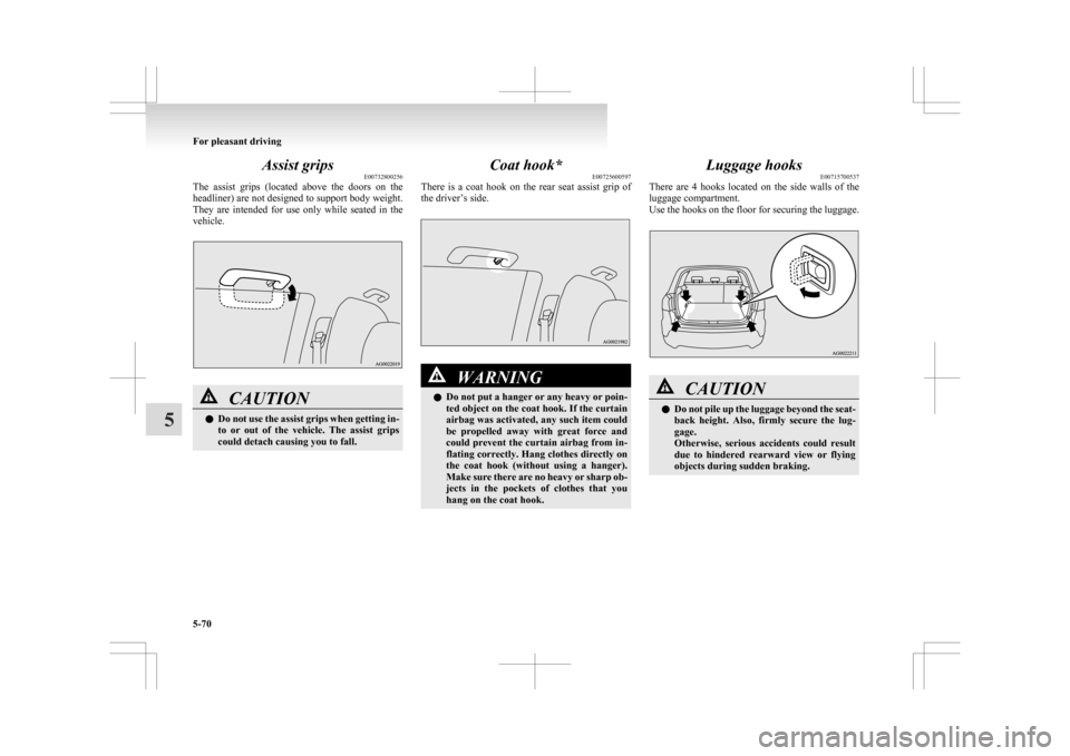
Assist grips
E00732800256
The
assist grips (located above the doors on the
headliner) are not designed to support body weight.
They are intended for use only while seated in the
vehicle. CAUTION
l
Do
not use the assist grips when getting in-
to or out of the vehicle. The assist grips
could detach causing you to fall. Coat hook*
E00725600597
There
is a coat hook on the rear seat assist grip of
the driver’s side. WARNING
l Do
not put a hanger or any heavy or poin-
ted object on the coat hook. If the curtain
airbag was activated, any such item could
be propelled away with great force and
could prevent the curtain airbag from in-
flating correctly. Hang clothes directly on
the coat hook (without using a hanger).
Make sure there are no heavy or sharp ob-
jects in the pockets of clothes that you
hang on the coat hook. Luggage hooks
E00715700537
There
are 4 hooks located on the side walls of the
luggage compartment.
Use the hooks on the floor for securing the luggage. CAUTION
l
Do
not pile up the luggage beyond the seat-
back height. Also, firmly secure the lug-
gage.
Otherwise, serious accidents could result
due to hindered rearward view or flying
objects during sudden braking. For pleasant driving
5-70
5
Page 280 of 368
If the vehicle breaks down
E00800101108
If
the vehicle breaks down on the road, move it to
the shoulder and turn on the hazard warning flash-
ers and set up a warning triangle, flashing lamp, etc.
Refer to “Hazard warning flasher switch” on page
3-50.
If the engine stops/fails
Vehicle operation and control are affected if the en-
gine stops.
Before moving the vehicle to a safe area, be aware
of the following:
l The brake booster becomes inoperative and
the pedal effort will increase. Press down the
brake pedal harder than usual.
l Since the power steering system is no longer
operative, the steering wheel feels heavy
when turning it. Emergency starting
E00800502503
If
the engine cannot be started because the battery
is weak or dead, the battery from another vehicle
can be used with jumper cables to start the engine. WARNING
l To
start the engine using jumper cables
connected to another vehicle, perform the
correct procedures according to the in-
struction below. Incorrect procedures
could result in a fire or explosion or dam-
age to the vehicles. CAUTION
l
Do
not attempt to start the engine by pull-
ing or pushing the vehicle.
It could damage your vehicle.
l Always wear protective eye goggles when
working near the battery.
l Keep the battery out of the reach of chil-
dren.
1. Get
the vehicles close enough so the jumper cables can reach, but be sure the vehicles
aren’t touching each other. CAUTION
l
Check
the other vehicle. It must have a 12-
volt battery.
If the other system isn’t 12-volt, shorting
can damage both vehicles. 2. Turn
off all lamps, heater and other electrical
loads.
3. Set the parking brake firmly on each vehicle. Put an A/T, CVT in “P” (PARK) or a M/T in
“N” (Neutral).
4. Turn the ignition switch to the “LOCK” posi- tion or put the operation mode in OFF. WARNING
l Perform
step 4 on both vehicles before-
hand.
Make sure that the cables or your clothes
cannot be caught by the fan or drive belt.
Personal injury could result.
5. Make
sure battery electrolyte is at the proper level.
Refer to “Battery” on page 8-08. WARNING
l If
electrolyte fluid is not visible, or ap-
pears to be frozen, Do Not Attempt Jump
Starting!
A battery might rupture or explode if the
temperature is below the freezing point
or if it is not filled to the proper level.
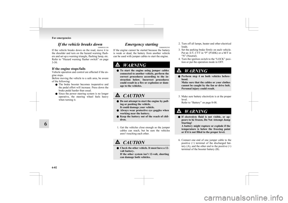
6. Connect
one end of one jumper cable to the positive (+) terminal of the discharged bat-
tery (A), and the other end to the positive (+)
terminal of the booster battery (B).
For emergencies
6-02
6
Page 281 of 368
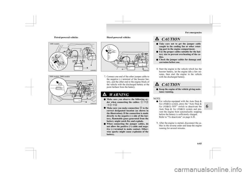
Petrol-powered vehicles1600 models
1800 models, 2000 models Diesel-powered vehicles
7. Connect one end of the other jumper cable to
the negative (-) terminal of the booster bat-
tery, and the other end to the engine block of
the vehicle with the discharged battery at the
point farthest from the battery. WARNING
l Make
sure you observe the following or-
der when connecting the cables: l
Make sure you make connection to the
correct
designated location (as shown in
the illustration). If the connection is made
directly to the negative (-) side of the bat-
tery, flammable gases generated from the
battery might catch fire and explode.
l When connecting the jumper cables, do
not allow the positive (+) cable and nega-
tive (-) terminal to make contact. Other-
wise sparks might cause explosion of the
battery. CAUTION
l
Take
care not to get the jumper cable
caught in the cooling fan or other rotat-
ing part in the engine compartment.
l Use the proper cables suitable for the bat-
tery size to prevent overheating of the ca-
bles.
l Check the jumper cables for damage and
corrosion before use.
8. Start
the engine in the vehicle which has the booster battery, let the engine idle a few mi-
nutes, then start the engine in the vehicle
with the discharged battery. CAUTION
l
Keep
the engine of the vehicle giving assis-
tance running.
NOTE l For
vehicles equipped with the Auto Stop &
Go (AS&G) system, press the “Auto Stop &
Go (AS&G) OFF” switch to deactivate the
Auto Stop & Go (AS&G) system and pre-
vent the engine from automatically stopping
before the battery is sufficiently charged.
Refer to “To deactivate” on page 4-20.
9. After the engine is started, disconnect the ca- bles in the reverse order and keep the engine
running for several minutes. For emergencies
6-03 6
Page 282 of 368

WARNING
l If the battery has to be charged while fit-
ted in the vehicle, disconnect the vehicle
side negative (-) terminal connected to the
battery.
l Keep sparks, cigarettes and flames away
from the battery because the battery may
produce an explosion.
l Use adequate ventilation when charging
or using the battery in an enclosed space.
l Remove all the caps before charging the
battery.
l Electrolyte is corrosive diluted sulphuric
acid.
If electrolyte (battery acid) comes into con-
tact with your hands, eyes, clothes and
the painted surface of your vehicle, it
should be thoroughly flushed with water.
If electrolyte gets in your eyes, flush them
with water immediately and thoroughly,
and get prompt medical attention.
NOTE l If
the vehicle is put in motion without fully
charging the battery, it might cause the loss
of smooth engine operation and the anti-lock
brake warning lamp to illuminate.
Refer to “Anti-lock brake system (ABS)” on
page 4-38. Engine overheating
E00800602269
When
the engine is overheating, the information
screen in the multi-information display will be in-
terrupted and the engine coolant temperature warn-
ing display will appear. Also “ ” will blink.
If
this occurs, take the following corrective meas-
ures: 1. Stop the vehicle in a safe place.
2. Check whether steam is coming from the en-gine compartment.
[If steam does not come from the engine com-
partment]
With the engine still running, raise the bon-
net to ventilate the engine compartment.
NOTE l For vehicles equipped with the Auto Stop &
Go (AS&G) system, press the “Auto Stop &
Go (AS&G) OFF” switch to deactivate the
Auto Stop & Go (AS&G) system before stop-
ping the vehicle.
Refer to “To deactivate” on page 4-20.
[If steam is coming from the engine compart-
ment]
Stop the engine, and when the steam stops,
raise the bonnet to ventilate the engine com-
partment. Restart the engine. WARNING
l Do
not open the bonnet while steam is com-
ing from the engine compartment. It
could cause steam or hot water to spurt
out, causing burns. Hot water could spurt
out even when there is no steam coming
out, and some parts will be very hot. Be
very careful when opening the bonnet.
l Be careful of hot steam, which could
cause the cap on the engine reserve tank
to blow off.
l Do not attempt to remove the radiator
cap (petrol-powered vehicles) or reserve
tank cap (diesel-powered vehicles) while
the engine is hot.
3. Confirm
that the cooling fans (A) are turn- ing. If the fans are not turning, stop the en-
gine immediately and have it checked.
Petrol-powered vehicles *: Front of the vehicleFor emergencies
6-04
6
Page 283 of 368

Diesel-powered vehicles*: Front of the vehicle
WARNING
l Be
careful not to get your hands or
clothes caught in the cooling fan.
4. When
the bar graph in the engine coolant tem- perature warning display in the multi-infor-
mation display drops, stop the engine.
Type 1
Type 2
Type 1
Type 2 5. Check
the coolant level in the reserve tank (B).
Petrol-powered vehicles
FULL
LOW
Diesel-powered vehicles
FULL
LOW WARNING
l If
there is none, make sure that the en-
gine has cooled down before removing
the radiator cap (C) (petrol-powered vehi-
cles) or reserve tank cap (C) (diesel-pow-
ered vehicles), because hot steam or boil-
ing water otherwise will gush from the fill-
er port and may scald you.
6. Fill
the reserve tank with coolant as needed. (Refer to the “Maintenance” section.) CAUTION
l
Do
not add coolant while the engine is
hot. Suddenly adding cold coolant could
damage the engine. Wait for the engine to
cool down, then add coolant a little at a
time.
7. Examine
the radiator hoses for coolant leak- age and the drive belt for looseness or damage.
If there is anything wrong with the cooling
system or drive belt, we recommend you to
have it checked and repaired. For emergencies
6-05 6
Page 286 of 368
l
Use the tyre sealant only at ambient tempera-
tures of -30 °C to + 60 °C.
l Effect an emergency repair without pulling
out the object (nail, screw, etc.) that is stuck
in the tyre.
l Do not use the tyre sealant if the tyre has
been damaged by being driven when insuffi-
ciently inflated (e.g. bumps, cuts, cracks etc.
on the tyre).
l Allow any tyre sealant seeping out of the
hole to dry, then pull off like a film.
l Wipe tyre sealant off the paintwork immedi-
ately with a damp cloth.
l Allow any tyre sealant in a damaged tyre to
dry out and dispose of it together with the tyre.
l Immediately change out of any clothes conta-
minated with the tyre sealant.
Before repairing a tyre, first stop your vehicle in a
safe, flat location. 1. Park the vehicle on level and stable ground.
2. Set the parking brake firmly.
3. On vehicles with M/T, stop the engine andmove the gearshift lever to the “R” (Reverse)
position.
On vehicles with CVT, move the selector lev-
er to the “P” (PARK) position and stop the en-
gine.
4. Turn on the hazard warning flashers and set up a warning triangle, flashing signal lamp,
etc., at an adequate distance from the vehi-
cle, and have all your passengers leave the ve-
hicle.
5. Take out the tyre sealant bottle and the com- pressor.
6. Shake the tyre sealant bottle well. NOTE
l In
cold conditions (when the ambient temper-
ature is 0 °C or lower), thickening of the tyre
sealant can make the tyre sealant hard to
squeeze out of the bottle. Warm the bottle in-
side the vehicle.
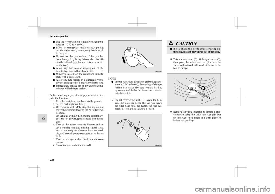
7. Do not remove the seal (C). Screw the filler hose (D) onto the bottle (E). As you screw
the filler hose onto the bottle, the seal will
break, allowing the sealant to be used. CAUTION
l
If
you shake the bottle after screwing on
the hose, sealant may spray out of the hose.
8. Take
the valve cap (F) off the tyre valve (G), then press the valve remover (H) onto the
valve as illustrated. Allow all of the air in the
tyre to escape. 9. Remove the valve insert (I) by turning it anti-
clockwise
using the valve remover (H). Put
the removed valve insert in a clean place so
it does not get dirty. For emergencies
6-08
6
Page 290 of 368
l
A tyre in which puncture sealant has been
used should ideally be replaced with a new
one. If you wish to have such a tyre properly
repaired for reuse, please contact a
MITSUBISHI MOTORS Authorized Service
Point or another specialist. Note that a proper
repair is impossible following an emergency
repair if the puncture hole cannot be located.
l Wipe away any sealant that gets on the
wheel. Provided the valve is replaced with a
new one, the wheel can be reused.
l The manufacturer is unable to guarantee that
all tyre punctures can be repaired with the
tyre repair kit, in particular cuts or perfora-
tions with a diameter of more than 4 mm or
away from the tyre’s tread. The manufacturer
is not liable for damage sustained through im-
proper use of the tyre repair kit.
l The manufacturer is not liable for damage sus-
tained through re-use of any tyre in which
tyre sealant has been used. How to change a tyre
E00801202637
Before
changing a tyre, first stop your vehicle in a
safe, flat location. 1. Park the vehicle on level and stable ground,free of loose pebbles, etc.
2. Set the parking brake firmly.
3. On vehicles with M/T, stop the engine and move the gearshift lever to the “R” (Reverse)
position.
On vehicles with CVT, move the selector lev-
er to the “P” (PARK) position and stop the en-
gine.
4. Turn on the hazard warning flashers and set up a warning triangle, flashing signal lamp,
etc., at an adequate distance from the vehi-
cle, and have all your passengers leave the ve-
hicle.
NOTE l The warning triangle and flashing signal
lamp do not come with your vehicle. It is rec-
ommended that you keep one in the vehicle
for use if needed.
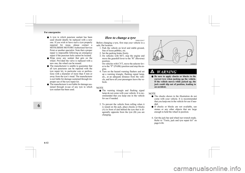
5. To prevent the vehicle from rolling when it is raised on the jack, place chocks or blocks
(A) in front of and behind the tyre that is di-
agonally opposite from the tyre (B) you are
changing. WARNING
l Be
sure to apply chocks or blocks to the
correct tyre when jacking up the vehicle.
If the vehicle moves while jacked up, the
jack could slip out of position, leading to
an accident.
NOTE l The
chocks shown in the illustration do not
come with your vehicle. It is recommended
that you keep one in the vehicle for use if nee-
ded.
l If chocks or blocks are not available, use
stones or any other objects that are large
enough to hold the wheel in position.
6. Get the jack bar and wheel nut wrench ready. Refer to “Tools, jack and tyre repair kit” on
page 6-06. For emergencies
6-12
6
Page 292 of 368
CAUTION
l
Do not install more than one temporary
spare wheel at the same time.
To remove the spare wheel E00803300117
1. Lift up the luggage floor board.
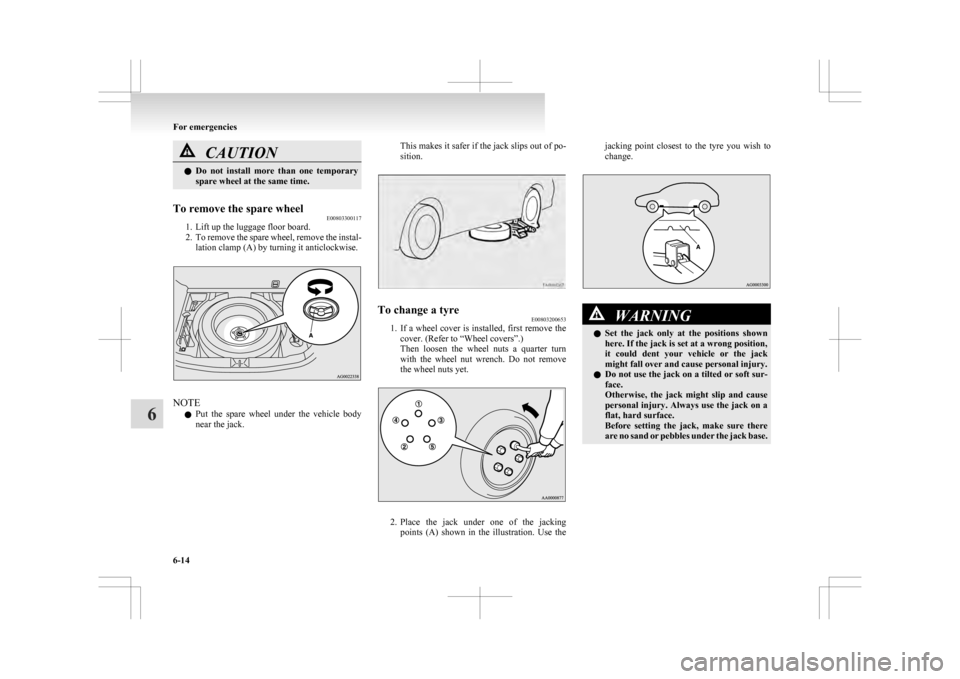
2. To
remove the spare wheel, remove the instal-
lation clamp (A) by turning it anticlockwise. NOTE
l Put
the spare wheel under the vehicle body
near the jack. This makes it safer if the jack slips out of po-
sition.
To change a tyre
E00803200653
1. If
a wheel cover is installed, first remove the
cover. (Refer to “Wheel covers”.)
Then loosen the wheel nuts a quarter turn
with the wheel nut wrench. Do not remove
the wheel nuts yet. 2. Place
the jack under one of the jacking
points (A) shown in the illustration. Use the jacking point closest to the tyre you wish to
change.
WARNING
l Set
the jack only at the positions shown
here. If the jack is set at a wrong position,
it could dent your vehicle or the jack
might fall over and cause personal injury.
l Do not use the jack on a tilted or soft sur-
face.
Otherwise, the jack might slip and cause
personal injury. Always use the jack on a
flat, hard surface.
Before setting the jack, make sure there
are no sand or pebbles under the jack base. For emergencies
6-14
6