2009 MERCEDES-BENZ GL SUV clock
[x] Cancel search: clockPage 180 of 309
temperature, or for about 30 minutes if the
engine is not at normal operating temper-
ature (if you had started the engine only
briefly), before measuring.
i If you wish to cancel the measurement,
press the *or& button on the multi-
function steering wheel.
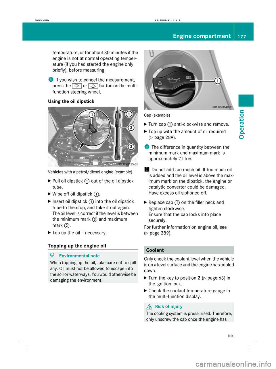
Using the oil dipstick Vehicles with a petrol/diesel engine (example)
X Pull oil dipstick :out of the oil dipstick
tube.
X Wipe off oil dipstick :.
X Insert oil dipstick :into the oil dipstick
tube to the stop, and take it out again.
The oil level is correct if the level is between
the minimum mark =and maximum
mark ;.
X Top up the oil if necessary.
Topping up the engine oil H
Environmental note
When topping up the oil, take care not to spill
any. Oil must not be allowed to escape into
the soil or waterways. You would otherwise be
damaging the environment. Cap (example)
X
Turn cap :anti-clockwise and remove.
X Top up with the amount of oil required
(Y page 289).
i The difference in quantity between the
minimum mark and maximum mark is
approximately 2 litres.
! Do not add too much oil. If too much oil
is added and the oil level is above the max-
imum mark on the dipstick, the engine or
catalytic converter could be damaged.
Have excess oil siphoned off.
X Replace cap :on the filler neck and
tighten clockwise.
Ensure that the cap locks into place
securely.
For further information on engine oil, see
(Y page 289). Coolant
Only check the coolant level when the vehicle
is on a level surface and the engine has cooled
down.
X Turn the key to position 2(Y page 63) in
the ignition lock.
X Check the coolant temperature gauge in
the multi-function display. G
Risk of injury
The cooling system is pressurised. Therefore,
only unscrew the cap once the engine has Engine compartment
177Operation
X164_AKB; 2; 3, en-GB
wobuchh,V ersion: 2.11.8.1
2009-03-31T14:14:58+02:00 - Seite 177 Z
Dateiname: 6515431202_buchblock.pdf; erzeugt am 01. Apr 2009 00:17:46; WK
Page 181 of 309
cooled down. The coolant temperature gauge
must display less than 70 †. Otherwise, you
could be scalded if hot coolant escapes.
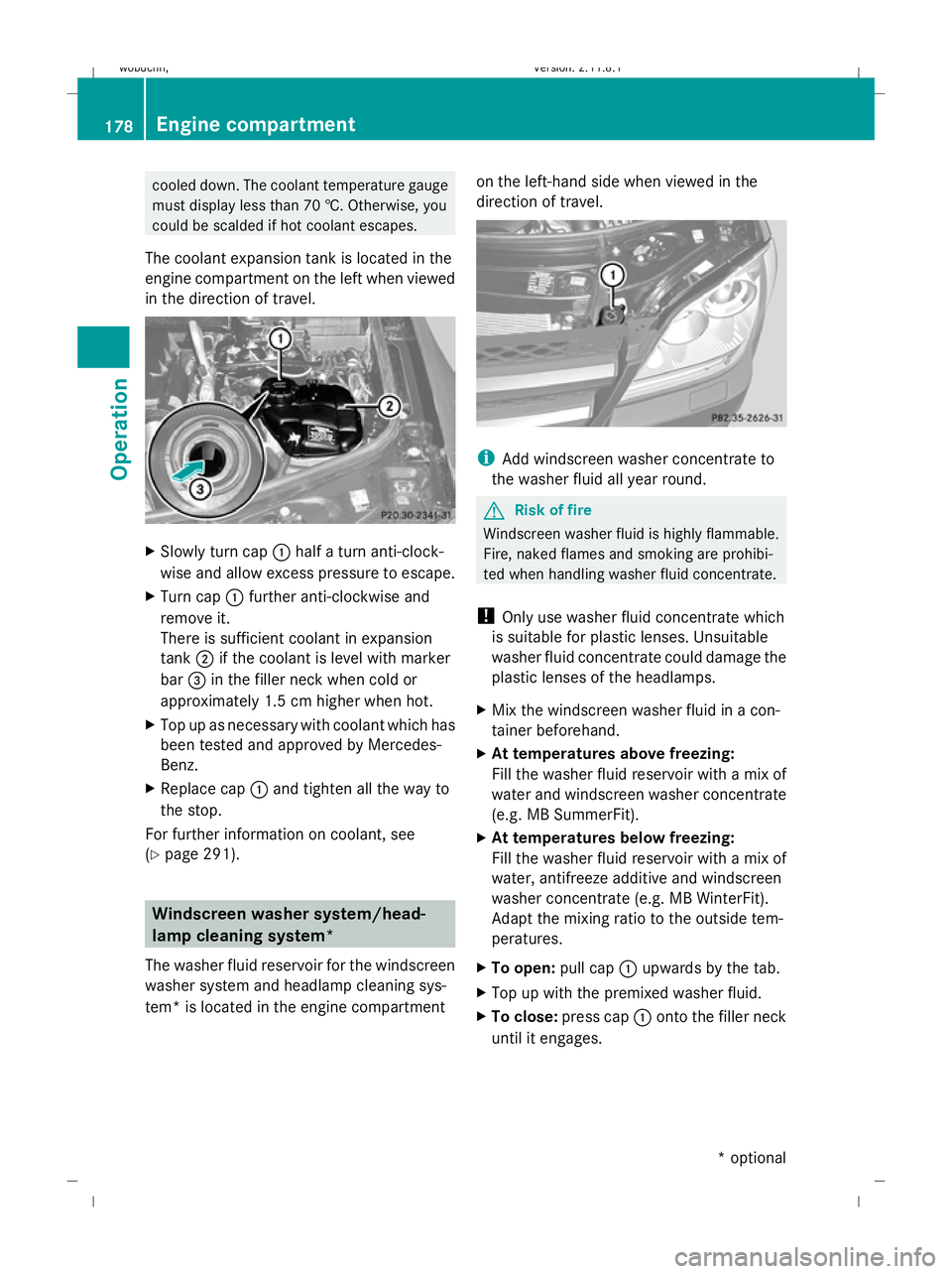
The coolant expansion tank is located in the
engine compartment on the left when viewed
in the direction of travel. X
Slowly turn cap :half a turn anti-clock-
wise and allow excess pressure to escape.
X Turn cap :further anti-clockwise and
remove it.
There is sufficient coolant in expansion
tank ;if the coolant is level with marker
bar =in the filler neck when cold or
approximately 1.5 cm higher when hot.
X Top up as necessary with coolant which has
been tested and approved by Mercedes-
Benz.
X Replace cap :and tighten all the way to
the stop.
For further information on coolant, see
(Y page 291). Windscreen washer system/head-
lamp cleaning system*
The washer fluid reservoir for the windscreen
washer system and headlamp cleaning sys-
tem* is located in the engine compartment on the left-hand side when viewed in the
direction of travel.
i
Add windscreen washer concentrate to
the washer fluid all year round. G
Risk of fire
Windscreen washer fluid is highly flammable.
Fire, naked flames and smoking are prohibi-
ted when handling washer fluid concentrate.
! Only use washer fluid concentrate which
is suitable for plastic lenses. Unsuitable
washer fluid concentrate could damage the
plastic lenses of the headlamps.
X Mix the windscreen washer fluid in a con-
tainer beforehand.
X At temperatures above freezing:
Fill the washer fluid reservoir with a mix of
water and windscreen washer concentrate
(e.g. MB SummerFit).
X At temperatures below freezing:
Fill the washer fluid reservoir with a mix of
water, antifreeze additive and windscreen
washer concentrate (e.g. MB WinterFit).
Adapt the mixing ratio to the outside tem-
peratures.
X To open: pull cap:upwards by the tab.
X Top up with the premixed washer fluid.
X To close: press cap :onto the filler neck
until it engages. 178
Engine compartmentOperation
* optional
X164_AKB; 2; 3, en-GB
wobuchh,
Version: 2.11.8.1 2009-03-31T14:14:58+02:00 - Seite 178
Dateiname: 6515431202_buchblock.pdf; erzeugt am 01. Apr 2009 00:17:47; WK
Page 197 of 309
X
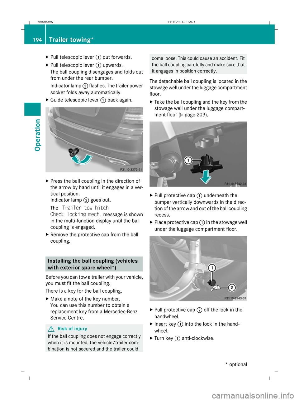
Pull telescopic lever :out forwards.
X Pull telescopic lever :upwards.
The ball coupling disengages and folds out
from under the rear bumper.
Indicator lamp ;flashes. The trailer power
socket folds away automatically.
X Guide telescopic lever :back again. X
Press the ball coupling in the direction of
the arrow by hand until it engages in a ver-
tical position.
Indicator lamp ;goes out.
The Trailer tow hitch
Check locking mech. message is shown
in the multi-function display until the ball
coupling is engaged.
X Remove the protective cap from the ball
coupling. Installing the ball coupling (vehicles
with exterior spare wheel*)
Before you can tow a trailer with your vehicle,
you must fit the ball coupling.
There is a key for the ball coupling.
X Make a note of the key number.
You can use this number to obtain a
replacement key from a Mercedes-Benz
Service Centre. G
Risk of injury
If the ball coupling does not engage correctly
when it is mounted, the vehicle/trailer com-
bination is not secured and the trailer could come loose. This could cause an accident. Fit
the ball coupling carefully and make sure that
it engages in position correctly.
The detachable ball coupling is located in the
stowage well under the luggage compartment
floor.
X Take the ball coupling and the key from the
stowage well under the luggage compart-
ment floor (Y page 209). X
Pull protective cap :underneath the
bumper vertically downwards in the direc-
tion of the arrow and out of the ball coupling
recess.
X Place protective cap :in the stowage well
under the luggage compartment floor. X
Pull protective cap ;off the lock in the
handwheel.
X Insert key :into the lock in the hand-
wheel.
X Turn key :anti-clockwise. 194
Trailer towing*Operation
* optional
X164_AKB; 2; 3, en-GB
wobuchh,
Version: 2.11.8.1 2009-03-31T14:14:58+02:00 - Seite 194
Dateiname: 6515431202_buchblock.pdf; erzeugt am 01. Apr 2009 00:17:51; WK
Page 198 of 309
i
The key remains inserted when you
remove the ball coupling. X
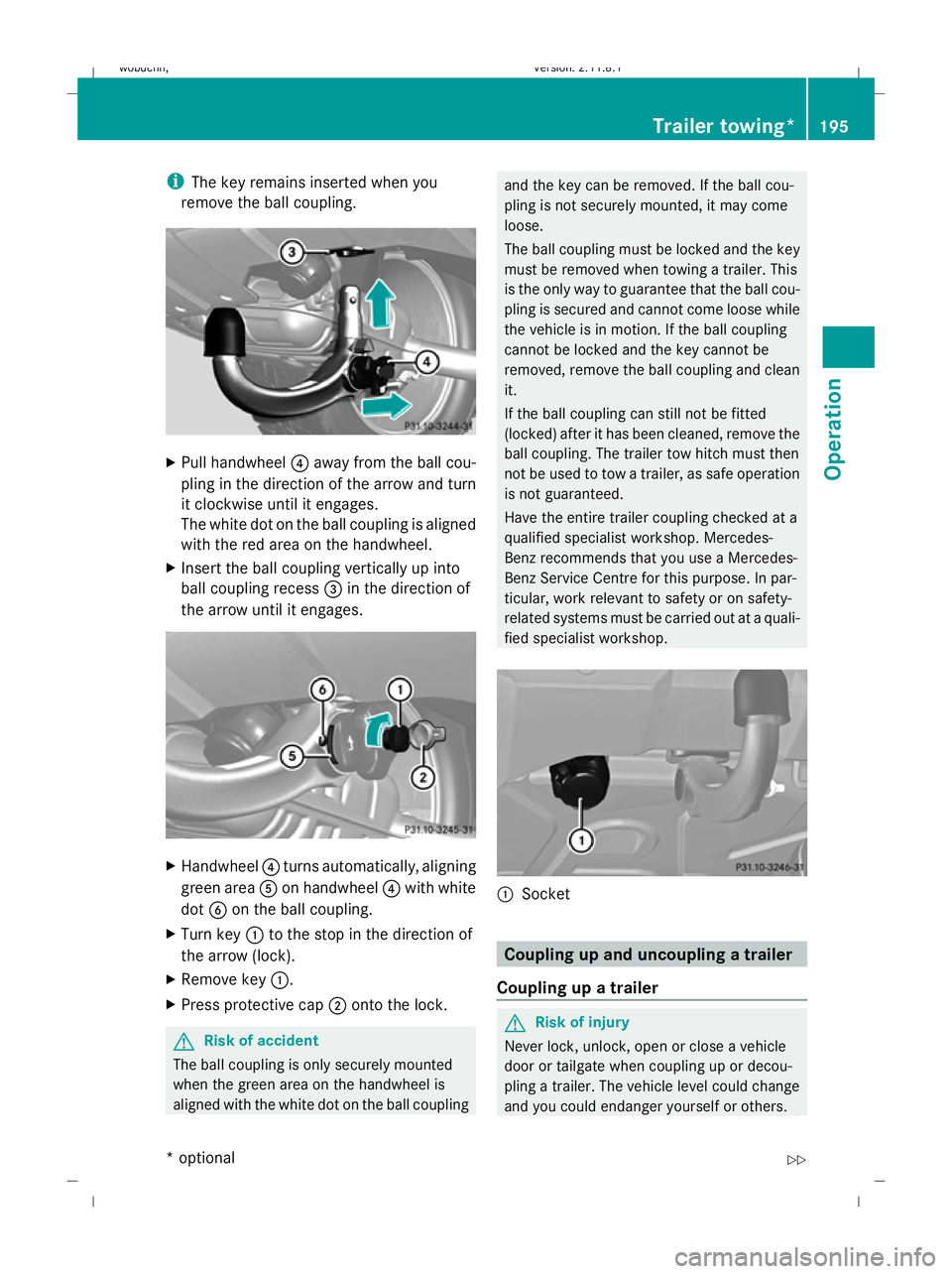
Pull handwheel ?away from the ball cou-
pling in the direction of the arrow and turn
it clockwise until it engages.
The white dot on the ball coupling is aligned
with the red area on the handwheel.
X Insert the ball coupling vertically up into
ball coupling recess =in the direction of
the arrow until it engages. X
Handwheel ?turns automatically, aligning
green area Aon handwheel ?with white
dot Bon the ball coupling.
X Turn key :to the stop in the direction of
the arrow (lock).
X Remove key :.
X Press protective cap ;onto the lock. G
Risk of accident
The ball coupling is only securely mounted
when the green area on the handwheel is
aligned with the white dot on the ball coupling and the key can be removed. If the ball cou-
pling is not securely mounted, it may come
loose.
The ball coupling must be locked and the key
must be removed when towing a trailer. This
is the only way to guarantee that the ball cou-
pling is secured and cannot come loose while
the vehicle is in motion. If the ball coupling
cannot be locked and the key cannot be
removed, remove the ball coupling and clean
it.
If the ball coupling can still not be fitted
(locked) after it has been cleaned, remove the
ball coupling. The trailer tow hitch must then
not be used to tow a trailer, as safe operation
is not guaranteed.
Have the entire trailer coupling checked at a
qualified specialist workshop. Mercedes-
Benz recommends that you use a Mercedes-
Benz Service Centre for this purpose. In par-
ticular, work relevant to safety or on safety-
related systems must be carried out at a quali-
fied specialist workshop. :
Socket Coupling up and uncoupling a trailer
Coupling up a trailer G
Risk of injury
Never lock, unlock, open or close a vehicle
door or tailgate when coupling up or decou-
pling a trailer. The vehicle level could change
and you could endanger yourself or others. Trailer towing*
195Operation
* optional
X164_AKB; 2; 3, en-GB
wobuchh,
Version: 2.11.8.1 2009-03-31T14:14:58+02:00 - Seite 195 Z
Dateiname: 6515431202_buchblock.pdf; erzeugt am 01. Apr 2009 00:17:51; WK
Page 201 of 309
climbing capability, decrease with increas-
ing altitude.
If the trailer swings from side to side:
X Do not accelerate.
X Do not counter-steer.
X Brake if necessary. G
Risk of accident
On no account should you attempt to draw the
vehicle/trailer combination out by increasing
speed. Folding in the ball coupling
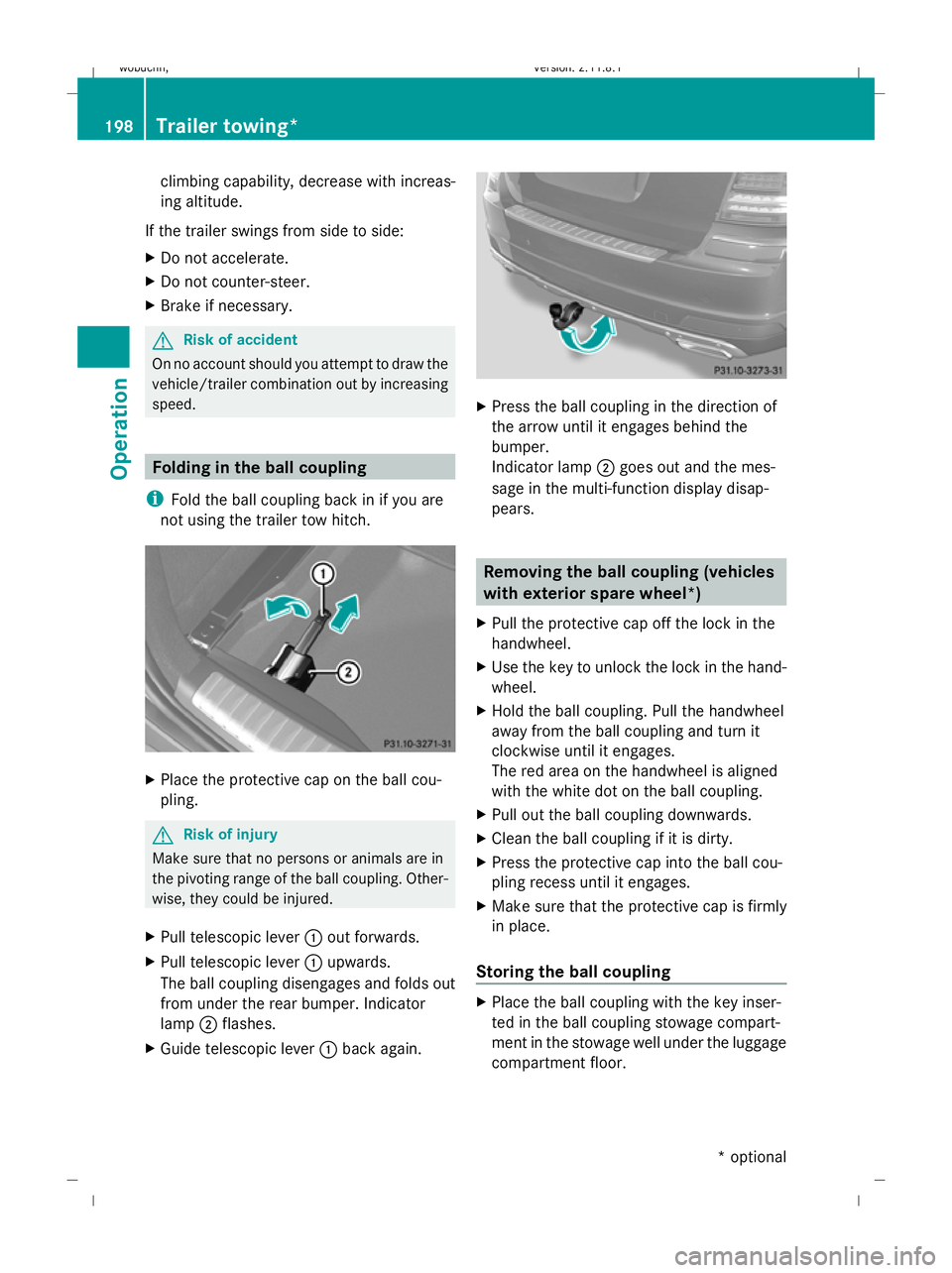
i Fold the ball coupling back in if you are
not using the trailer tow hitch. X
Place the protective cap on the ball cou-
pling. G
Risk of injury
Make sure that no persons or animals are in
the pivoting range of the ball coupling. Other-
wise, they could be injured.
X Pull telescopic lever :out forwards.
X Pull telescopic lever :upwards.
The ball coupling disengages and folds out
from under the rear bumper. Indicator
lamp ;flashes.
X Guide telescopic lever :back again. X
Press the ball coupling in the direction of
the arrow until it engages behind the
bumper.
Indicator lamp ;goes out and the mes-
sage in the multi-function display disap-
pears. Removing the ball coupling (vehicles
with exterior spare wheel*)
X Pull the protective cap off the lock in the
handwheel.
X Use the key to unlock the lock in the hand-
wheel.
X Hold the ball coupling. Pull the handwheel
away from the ball coupling and turn it
clockwise until it engages.
The red area on the handwheel is aligned
with the white dot on the ball coupling.
X Pull out the ball coupling downwards.
X Clean the ball coupling if it is dirty.
X Press the protective cap into the ball cou-
pling recess until it engages.
X Make sure that the protective cap is firmly
in place.
Storing the ball coupling X
Place the ball coupling with the key inser-
ted in the ball coupling stowage compart-
ment in the stowage well under the luggage
compartment floor. 198
Trailer towing*Operation
* optional
X164_AKB; 2; 3, en-GB
wobuchh,
Version: 2.11.8.1 2009-03-31T14:14:58+02:00 - Seite 198
Dateiname: 6515431202_buchblock.pdf; erzeugt am 01. Apr 2009 00:17:52; WK
Page 202 of 309

G
Risk of accident
Do not carry the ball coupling in the vehicle
interior if it is not secured.
Otherwise, you and others could be injured by
the ball coupling being thrown around if you:
R brake sharply
R change direction suddenly
R are involved in an accident
Information on cleaning and care of the trailer
coupling can be found at (Y page 203).Trailer power supply
When it leaves the factory, your vehicle's
trailer socket outlet is equipped with a per-
manent power supply and a power supply that
is switched on via the ignition lock.
The permanent power supply is supplied via
trailer socket pin 9.
The power supply that is switched on via the
ignition lock is supplied via trailer socket
pin 10.
! You can connect consumers with a power
rating of up to 240 W to the permanent
power supply and up to 180 W to the power
supply that is switched on via the ignition
lock.
You must not charge a trailer battery using
the power supply.
The trailer's turn signal lamps are only guar-
anteed to function when bulbs are used.
You can obtain further information about
installing the trailer electrics from a qualified
specialist workshop, e.g. a Mercedes-Benz
Service Centre.
X To switch the connected power supply
on or off: turn the key in the ignition lock
to position 2or 0, respectively. Trailer with 7-pin connector
If your trailer has a 7-pin connector, you can
connect it to the 13-pin socket on the ball
coupling using an adapter or, if necessary, an
adapter cable. Both of these can be obtained
at a qualified specialist workshop, e.g. at a
Mercedes-Benz Service Centre.
Fitting the adapter X
Open the socket cover.
X Insert connector with lug :into
groove ;on the socket and turn the con-
nector clockwise to the stop.
X Make the cover engage.
X If you are using an adapter cable, secure
the cable to the trailer with cable ties.
! Make sure that there is sufficient cable
play so that the cable cannot become
detached when cornering. Service
ASSYST PLUS service interval display
The ASSYST PLUS service interval display
informs you of the next service due date.
The service due date is shown in the multi-
function display, for example:
Service A in .. days
Service A in .. km
Service A due now
The letter indicates how much time the work-
shop will require to carry out the service work. Service
199Operation
X164_AKB; 2; 3, en-GB
wobuchh, Version: 2.11.8.1 2009-03-31T14:14:58+02:00 - Seite 199 Z
Dateiname: 6515431202_buchblock.pdf; erzeugt am 01. Apr 2009 00:17:52; WK
Page 214 of 309
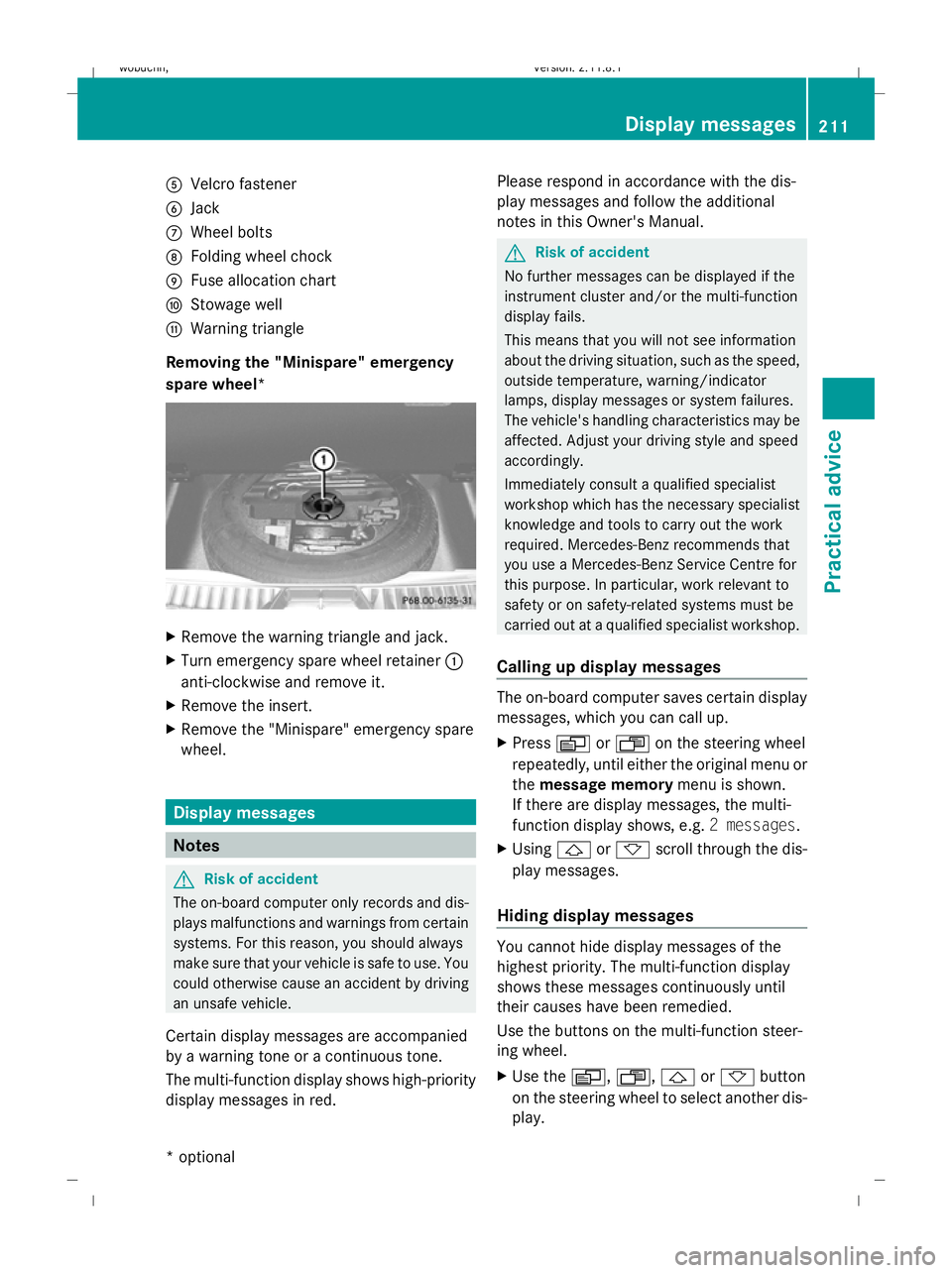
A
Velcro fastener
B Jack
C Wheel bolts
D Folding wheel chock
E Fuse allocation chart
F Stowage well
G Warning triangle
Removing the "Minispare" emergency
spare wheel* X
Remove the warning triangle and jack.
X Turn emergency spare wheel retainer :
anti-clockwise and remove it.
X Remove the insert.
X Remove the "Minispare" emergency spare
wheel. Display messages
Notes
G
Risk of accident
The on-board computer only records and dis-
plays malfunctions and warnings from certain
systems. For this reason, you should always
make sure that your vehicle is safe to use. You
could otherwise cause an accident by driving
an unsafe vehicle.
Certain display messages are accompanied
by a warning tone or a continuous tone.
The multi-function display shows high-priority
display messages in red. Please respond in accordance with the dis-
play messages and follow the additional
notes in this Owner's Manual. G
Risk of accident
No further messages can be displayed if the
instrument cluster and/or the multi-function
display fails.
This means that you will not see information
about the driving situation, such as the speed,
outside temperature, warning/indicator
lamps, display messages or system failures.
The vehicle's handling characteristics may be
affected. Adjust your driving style and speed
accordingly.
Immediately consult a qualified specialist
workshop which has the necessary specialist
knowledge and tools to carry out the work
required. Mercedes-Benz recommends that
you use a Mercedes-Benz Service Centre for
this purpose. In particular, work relevant to
safety or on safety-related systems must be
carried out at a qualified specialist workshop.
Calling up display messages The on-board computer saves certain display
messages, which you can call up.
X
Press VorU on the steering wheel
repeatedly, until either the original menu or
the message memory menu is shown.
If there are display messages, the multi-
function display shows, e.g. 2 messages.
X Using &or* scroll through the dis-
play messages.
Hiding display messages You cannot hide display messages of the
highest priority. The multi-function display
shows these messages continuously until
their causes have been remedied.
Use the buttons on the multi-function steer-
ing wheel.
X
Use the V,U,&or* button
on the steering wheel to select another dis-
play. Display messages
211Practical advice
* optional
X164_AKB; 2; 3, en-GB
wobuchh,
Version: 2.11.8.1 2009-03-31T14:14:58+02:00 - Seite 211 Z
Dateiname: 6515431202_buchblock.pdf; erzeugt am 01. Apr 2009 00:17:58; WK
Page 253 of 309
Locking/unlocking in an emergency
Emergency key element
If you use the emergency key element to
unlock and open the driver's door, the anti-
theft alarm system* will be triggered
(Y page 54).
There are several ways to turn off the alarm:
X Press the %or& button on the key.
or
X Insert the key into the ignition lock.
or
X Press the start/stop button *in the ignition
lock. The key must be in the vehicle.
or
X Lock or unlock the vehicle using KEYLESS
GO*. The key must be outside the vehicle.
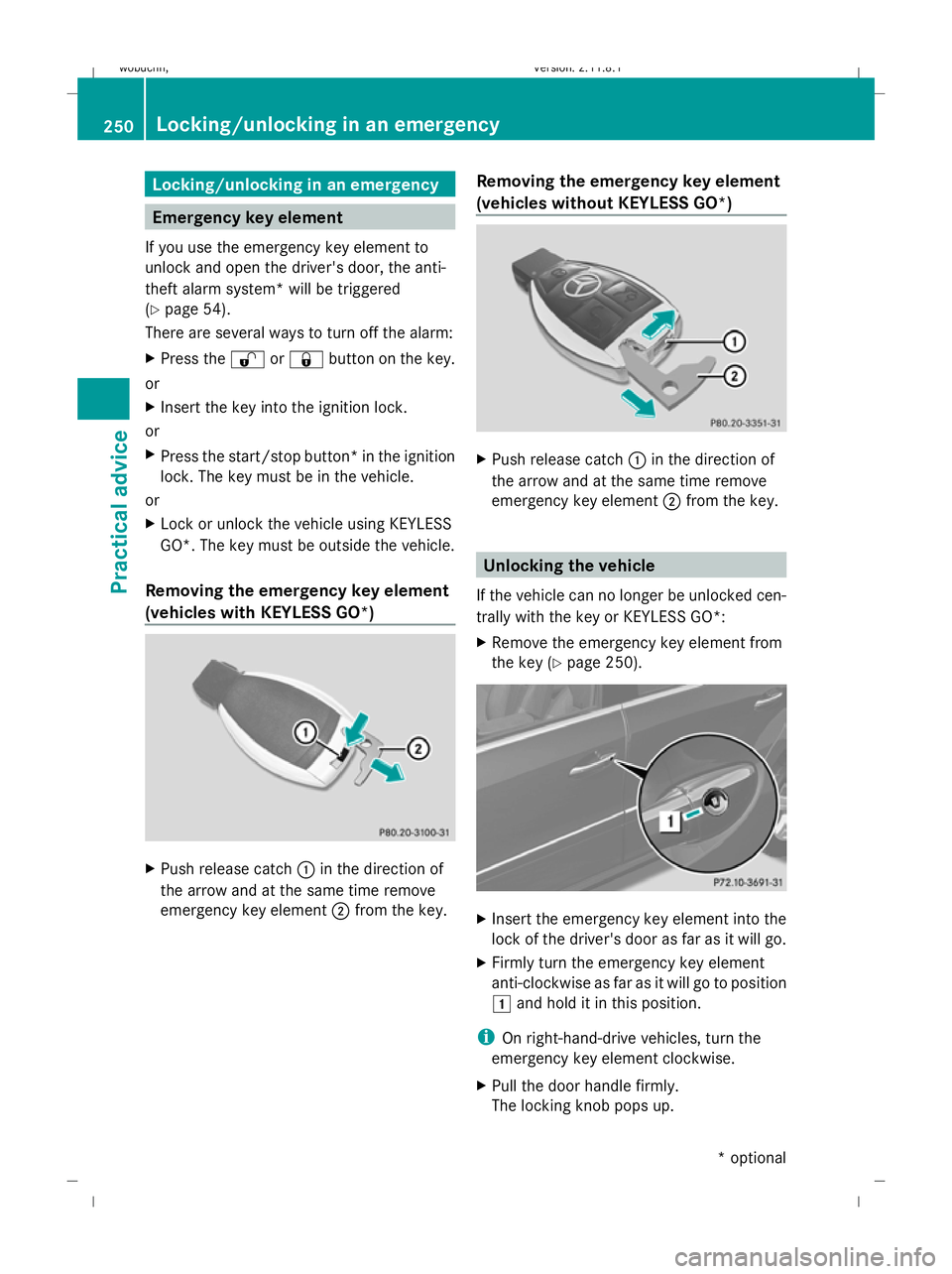
Removing the emergency key element
(vehicles with KEYLESS GO*) X
Push release catch :in the direction of
the arrow and at the same time remove
emergency key element ;from the key. Removing the emergency key element
(vehicles without KEYLESS GO*) X
Push release catch :in the direction of
the arrow and at the same time remove
emergency key element ;from the key. Unlocking the vehicle
If the vehicle can no longer be unlocked cen-
trally with the key or KEYLESS GO*:
X Remove the emergency key element from
the key (Y page 250). X
Insert the emergency key element into the
lock of the driver's door as far as it will go.
X Firmly turn the emergency key element
anti-clockwise as far as it will go to position
1 and hold it in this position.
i On right-hand-drive vehicles, turn the
emergency key element clockwise.
X Pull the door handle firmly.
The locking knob pops up. 250
Locking/unlocking in an emergencyPractical advice
* optional
X164_AKB; 2; 3, en-GB
wobuchh
,V ersion: 2.11.8.1
2009-03-31T14:14:58+02:00 - Seite 250
Dateiname: 6515431202_buchblock.pdf; erzeugt am 01. Apr 2009 00:18:03; WK