2009 MERCEDES-BENZ GL SUV wheel
[x] Cancel search: wheelPage 272 of 309

X
On downhill gradients: place the folding
wheel chock or similar behind the wheels
of the front and rear axle. X
Using wheel wrench ?, loosen the bolts on
the wheel you wish to change by about one
full turn. Do not unscrew the bolts com-
pletely.
X Remove the spare wheel from the exterior
bracket* (Y page 210).
or
X Remove the "Minispare" emergency spare
wheel* from the stowage well under the
luggage compartment floor (Y page 210).
Raising the vehicle G
Risk of injury
The jack is designed only to raise the vehicle
for a short time while a wheel is being
changed.
The vehicle must be placed on stands if you
intend to work under it.
Make sure that the jack is placed on a firm,
non-slip, level surface. Do not use wooden
blocks or similar objects as a jack underlay.
The vehicle could otherwise fall off the jack
and seriously injure you.
Do not start the engine at any time while the
wheel is being changed.
Do not lie under the vehicle when it is being
supported by the jack. If you do not raise the
vehicle as described, it could slip off the jack (e.g. if the engine is started or a door or the
tailgate is opened or closed), and you could
be seriously injured.
G
Risk of accident
If you fail to position the jack correctly, the
vehicle may:
R slip off the jack
R injure you or others
R be damaged
Thus, it is important to make sure that the jack
is positioned correctly in the respective jack-
ing points. Before positioning the jack,
remove any dirt that may have collected in the
jacking points.
The jacking points for the jack are located
behind the wheel housings of the front wheels
and in front of the wheel housings of the rear
wheels (arrows). X
Position jack ;at jacking point :. Flat tyre
269Practical advice
* optional
X164_AKB; 2; 3, en-GB
wobuchh,
Version: 2.11.8.1 2009-03-31T14:14:58+02:00 - Seite 269 Z
Dateiname: 6515431202_buchblock.pdf; erzeugt am 01. Apr 2009 00:18:12; WK
Page 273 of 309

X
Make sure that the base of the jack is posi-
tioned directly under jacking point :.
X Take the socket wrench and ratchet ring
spanner =out of the vehicle tool kit.
X Insert the socket into ratchet ring spanner
= and place it on the jack so that the let-
tering AUFis visible.
X Raise the vehicle with ratchet ring spanner
= until the tyre is at most three centime-
tres off the ground. X
Unscrew the uppermost wheel bolt com-
pletely.
X In place of the wheel bolt, screw centring
pin ?from the vehicle tool kit into the
thread.
X Unscrew the remaining wheel bolts fully.
! Do not place wheel bolts in sand or on a
dirty surface. The bolt and wheel hub
threads could otherwise be damaged when
you screw them in.
X Remove the wheel. Fitting a new wheel G
Risk of accident
Replace damaged or corroded wheel bolts.
Never oil or grease wheel bolts. This could
cause the bolts to loosen in the wheel hub. G
Risk of accident
If a wheel hub thread is damaged, do not drive
the vehicle any further. Consult a qualified
specialist workshop which has the necessary
specialist knowledge and tools to carry out
the work required. Mercedes-Benz recom-
mends that you use a Mercedes-Benz Service
Centre or "Service 24". In particular, work rel-
evant to safety or on safety-related systems
must be carried out at a qualified specialist
workshop. G
Risk of accident
Only use wheel bolts that have been designed
for the wheel and the vehicle. For safety rea-
sons, Mercedes-Benz recommends that you
only use wheel bolts which have been
approved for Mercedes-Benz and the respec-
tive wheel. Other bolts may work loose or
damage the brake system.
Do not tighten the wheel bolts completely
while the vehicle is still jacked up. The vehicle
could topple off the jack. 1
Wheel bolts for 18", 19" and 20" wheels
2 Wheel bolts for the "Minispare" emer-
gency spare wheel* 270
Flat tyrePractical advice
* optional
X164_AKB; 2; 3, en-GB
wobuchh,
Version: 2.11.8.1 2009-03-31T14:14:58+02:00 - Seite 270
Dateiname: 6515431202_buchblock.pdf; erzeugt am 01. Apr 2009 00:18:13; WK
Page 274 of 309

!
Always use wheel bolts ;to fit the
"Minispare" emergency spare wheel*.
Using other wheel bolts to fit the
"Minispare" emergency spare wheel* could
damage the brake system.
i Wheel bolts 2can be found with the
"Minispare" emergency spare wheel*.
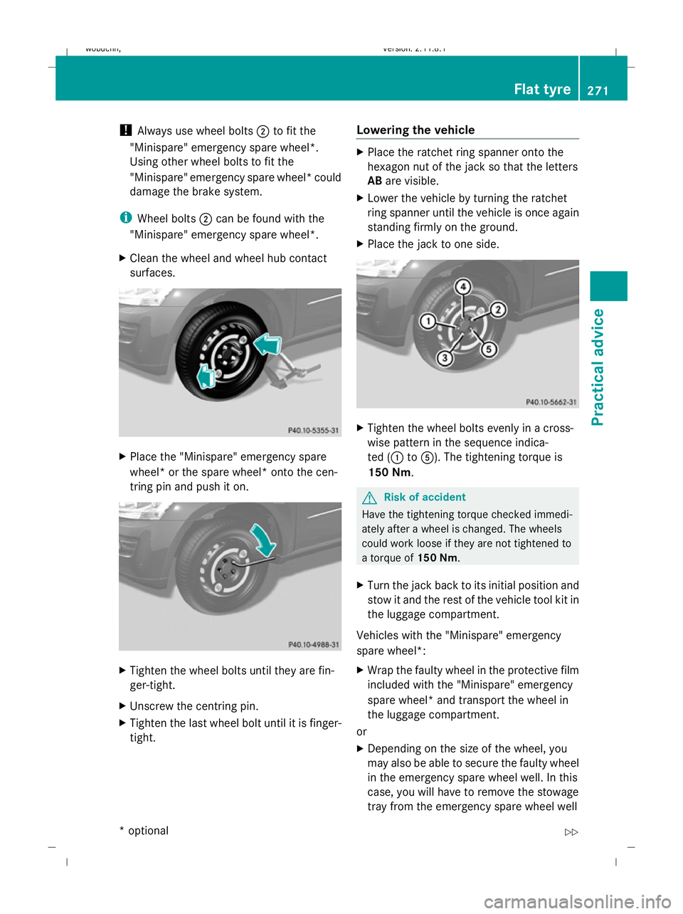
X Clean the wheel and wheel hub contact
surfaces. X
Place the "Minispare" emergency spare
wheel* or the spare wheel* onto the cen-
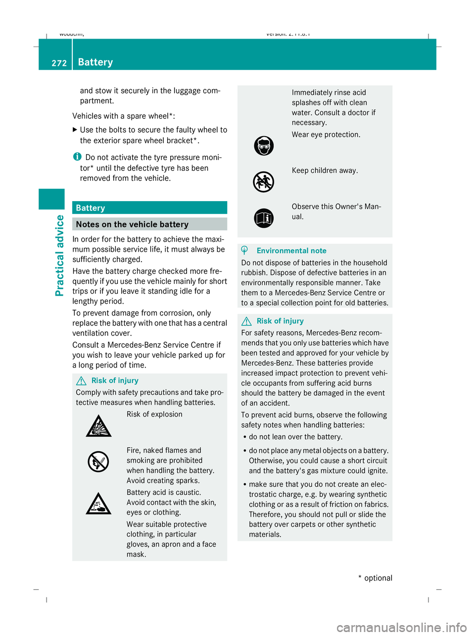
tring pin and push it on. X
Tighten the wheel bolts until they are fin-
ger-tight.
X Unscrew the centring pin.
X Tighten the last wheel bolt until it is finger-
tight. Lowering the vehicle X
Place the ratchet ring spanner onto the
hexagon nut of the jack so that the letters
AB are visible.
X Lower the vehicle by turning the ratchet
ring spanner until the vehicle is once again
standing firmly on the ground.
X Place the jack to one side. X
Tighten the wheel bolts evenly in a cross-
wise pattern in the sequence indica-
ted (: toA). The tightening torque is
150 Nm. G
Risk of accident
Have the tightening torque checked immedi-
ately after a wheel is changed. The wheels
could work loose if they are not tightened to
a torque of 150 Nm.
X Turn the jack back to its initial position and
stow it and the rest of the vehicle tool kit in
the luggage compartment.
Vehicles with the "Minispare" emergency
spare wheel*:
X Wrap the faulty wheel in the protective film
included with the "Minispare" emergency
spare wheel* and transport the wheel in
the luggage compartment.
or
X Depending on the size of the wheel, you
may also be able to secure the faulty wheel
in the emergency spare wheel well. In this
case, you will have to remove the stowage
tray from the emergency spare wheel well Flat tyre
271Practical advice
* optional
X164_AKB; 2; 3, en-GB
wobuchh,
Version: 2.11.8.1 2009-03-31T14:14:58+02:00 - Seite 271 Z
Dateiname: 6515431202_buchblock.pdf; erzeugt am 01. Apr 2009 00:18:13; WK
Page 275 of 309

and stow it securely in the luggage com-
partment.
Vehicles with a spare wheel*:
X Use the bolts to secure the faulty wheel to
the exterior spare wheel bracket*.
i Do not activate the tyre pressure moni-
tor* until the defective tyre has been
removed from the vehicle. Battery
Notes on the vehicle battery
In order for the battery to achieve the maxi-
mum possible service life, it must always be
sufficiently charged.
Have the battery charge checked more fre-
quently if you use the vehicle mainly for short
trips or if you leave it standing idle for a
lengthy period.
To prevent damage from corrosion, only
replace the battery with one that has a central
ventilation cover.
Consult a Mercedes-Benz Service Centre if
you wish to leave your vehicle parked up for
a long period of time. G
Risk of injury
Comply with safety precautions and take pro-
tective measures when handling batteries. Risk of explosion
Fire, naked flames and
smoking are prohibited
when handling the battery.
Avoid creating sparks. Battery acid is caustic.
Avoid contact with the skin,
eyes or clothing.
Wear suitable protective
clothing, in particular
gloves, an apron and a face
mask. Immediately rinse acid
splashes off with clean
water. Consult a doctor if
necessary.
Wear eye protection.
Keep children away.
Observe this Owner's Man-
ual.
H
Environmental note
Do not dispose of batteries in the household
rubbish. Dispose of defective batteries in an
environmentally responsible manner. Take
them to a Mercedes-Benz Service Centre or
to a special collection point for old batteries. G
Risk of injury
For safety reasons, Mercedes-Benz recom-
mends that you only use batteries which have
been tested and approved for your vehicle by
Mercedes-Benz. These batteries provide
increased impact protection to prevent vehi-
cle occupants from suffering acid burns
should the battery be damaged in the event
of an accident.
To prevent acid burns, observe the following
safety notes when handling batteries:
R do not lean over the battery.
R do not place any metal objects on a battery.
Otherwise, you could cause a short circuit
and the battery's gas mixture could ignite.
R make sure that you do not create an elec-
trostatic charge, e.g. by wearing synthetic
clothing or as a result of friction on fabrics.
Therefore, you should not pull or slide the
battery over carpets or other synthetic
materials. 272
BatteryPractical advice
* optional
X164_AKB; 2; 3, en-GB
wobuchh,
Version: 2.11.8.1 2009-03-31T14:14:58+02:00 - Seite 272
Dateiname: 6515431202_buchblock.pdf; erzeugt am 01. Apr 2009 00:18:14; WK
Page 282 of 309

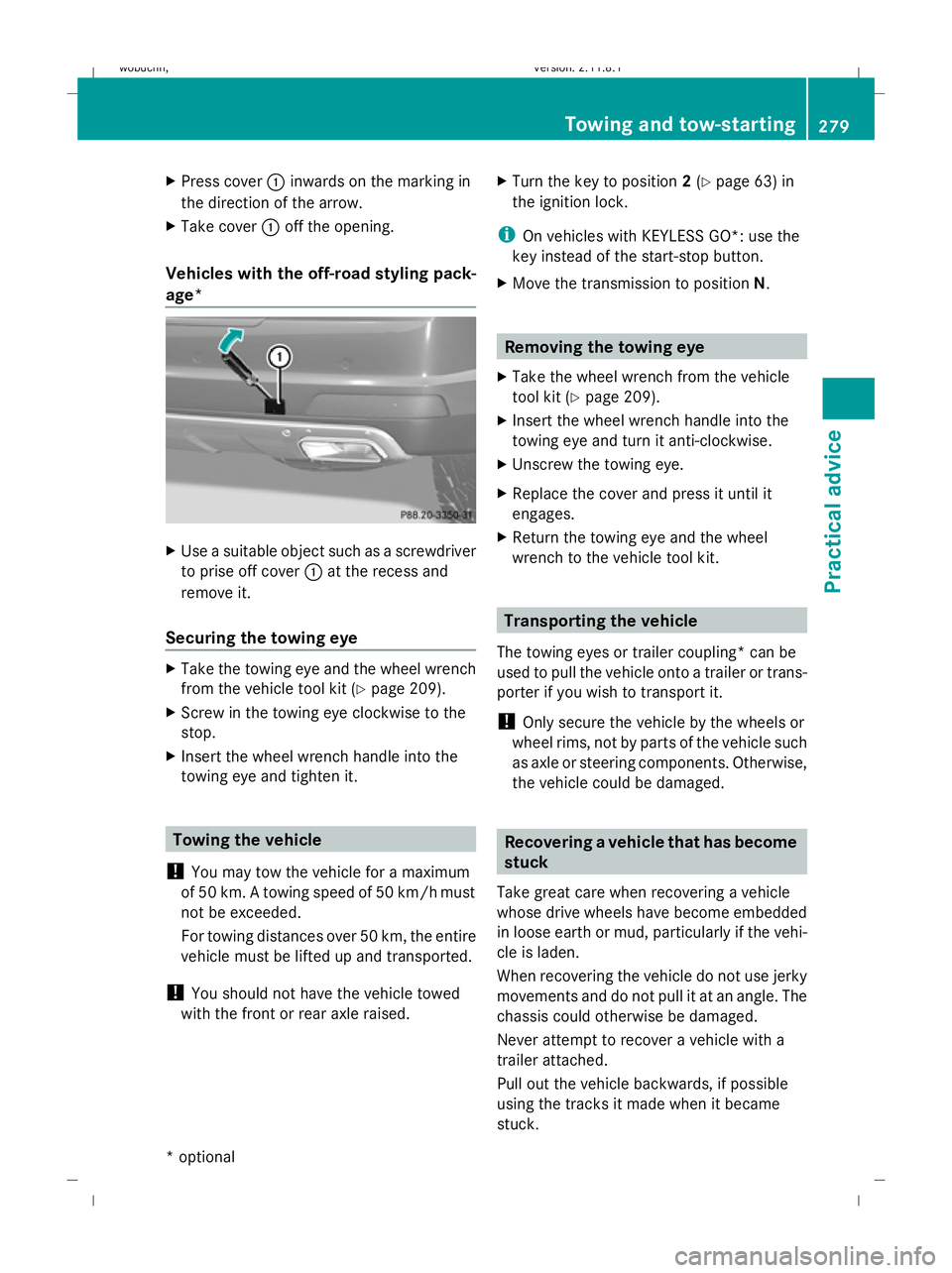
X
Press cover :inwards on the marking in
the direction of the arrow.
X Take cover :off the opening.
Vehicles with the off-road styling pack-
age* X
Use a suitable object such as a screwdriver
to prise off cover :at the recess and
remove it.
Securing the towing eye X
Take the towing eye and the wheel wrench
from the vehicle tool kit (Y page 209).
X Screw in the towing eye clockwise to the
stop.
X Insert the wheel wrench handle into the
towing eye and tighten it. Towing the vehicle
! You may tow the vehicle for a maximum
of 50 km. A towing speed of 50 km/hm ust
not be exceeded.
For towing distances over 50 km, the entire
vehicle must be lifted up and transported.
! You should not have the vehicle towed
with the front or rear axle raised. X
Turn the key to position 2(Y page 63) in
the ignition lock.
i On vehicles with KEYLESS GO*: use the
key instead of the start-stop button.
X Move the transmission to position N. Removing the towing eye
X Take the wheel wrench from the vehicle
tool kit (Y page 209).
X Insert the wheel wrench handle into the
towing eye and turn it anti-clockwise.
X Unscrew the towing eye.
X Replace the cover and press it until it
engages.
X Return the towing eye and the wheel
wrench to the vehicle tool kit. Transporting the vehicle
The towing eyes or trailer coupling* can be
used to pull the vehicle onto a trailer or trans-
porter if you wish to transport it.
! Only secure the vehicle by the wheels or
wheel rims, not by parts of the vehicle such
as axle or steering components. Otherwise,
the vehicle could be damaged. Recovering a vehicle that has become
stuck
Take great care when recovering a vehicle
whose drive wheels have become embedded
in loose earth or mud, particularly if the vehi-
cle is laden.
When recovering the vehicle do not use jerky
movements and do not pull it at an angle. The
chassis could otherwise be damaged.
Never attempt to recover a vehicle with a
trailer attached.
Pull out the vehicle backwards, if possible
using the tracks it made when it became
stuck. Towing and tow-starting
279Practical advice
* optional
X164_AKB; 2; 3, en-GB
wobuchh,
Version: 2.11.8.1 2009-03-31T14:14:58+02:00 - Seite 279 Z
Dateiname: 6515431202_buchblock.pdf; erzeugt am 01. Apr 2009 00:18:20; WK
Page 286 of 309

Notes on the technical data
.............284
Genuine Mercedes-Benz parts .........284
Vehicle electronics ...........................284
Vehicle identification plates ............286
Service products and capacities .....287
Vehicle data, GL 450 4MATIC ..........292
Vehicle data, GL 500 4MATIC ..........292
Vehicle data, GL 350 CDI 4MATIC
BlueEFFICIENCY ................................ 293
Vehicle data, GL 350 BlueTEC .........293
Vehicle data, GL 450 CDI 4MATIC ...294
Tailgate opening dimensions ...........295
Tyres and wheels .............................. 295
Trailer coupling* ............................... 297
Frequencies for garage door open-
ers* .................................................... 298 283Technical data
X164_AKB; 2; 3, en-GB
wobuchh,
Version: 2.11.8.1 2009-03-31T14:14:58+02:00 - Seite 283
Dateiname: 6515431202_buchblock.pdf; erzeugt am 01. Apr 2009 00:18:22; WK
Page 295 of 309

Vehicle data, GL 450 4MATIC
Vehicle dimensions
Vehicle length
(ECE)
5099 mm
Vehicle width
including exterior
mirrors
2124 mm
Minimum vehicle
height
38 1840 mm
Maximum vehicle
height
38 1950 mm
Minimum ground
clearance
38 202 mm
Maximum ground
clearance
38 307 mm
Ground clearance
when the suspen-
sion is set to High-
way level
38 217 mm
Wheel base
3075 mm
Vehicle weights
Unladen weight
(in accordance
with EC directive)
2430 kg
The unladen weight includes the driver
(68 kg), luggage (7 kg) and all fluids (fuel
tank 90% full). Items of optional equipment
increase the unladen weight and reduce the
maximum payload. Maximum roof
load
90 kg
You will find weight information specific to
the vehicle on the vehicle identification
plate (Y page 286). Vehicle data, GL 500 4MATIC
Vehicle dimensions
Vehicle length
(ECE)
5099 mm
Vehicle width
including exterior
mirrors 2124 mm
Minimum vehicle
height 39 1840 mm
Maximum vehicle
height
39 1950 mm
Minimum ground
clearance
39 202 mm
Maximum ground
clearance
39 307 mm
Ground clearance
when the suspen-
sion is set to High-
way level 39 217 mm
Wheel base
3075 mm
Vehicle weights
Unladen weight
(in accordance
with EC directive) 2445 kg
The unladen weight includes the driver
(68 kg), luggage (7 kg) and all fluids (fuel
tank 90% full). Items of optional equipment
increase the unladen weight and reduce the
maximum payload.
Maximum roof
load 90 kg
You will find weight information specific to
the vehicle on the vehicle identification
plate (Y page 286). 38
The value stated may vary due to the tyres fitted and the state of the suspension system.
39 The value stated may vary due to the tyres fitted and the state of the suspension system. 292
Vehicle data, GL 500 4MATICTechnical data
X164_AKB; 2; 3, en-GB
wobuchh,
Version: 2.11.8.1
2009-03-31T14:14:58+02:00 - Seite 292
Dateiname: 6515431202_buchblock.pdf; erzeugt am 01. Apr 2009 00:18:25; WK
Page 296 of 309

Vehicle data, GL 350 CDI 4MATIC
BlueEFFICIENCY Vehicle dimensions
Vehicle length
(ECE) 5099 mm
Vehicle width
including exterior
mirrors
2124 mm
Minimum vehicle
height
40 1840 mm
Maximum vehicle
height
40 1950 mm
Minimum ground
clearance
40 202 mm
Maximum ground
clearance
40 307 mm
Ground clearance
when the suspen-
sion is set to High-
way level
40 217 mm
Wheel base
3075 mm Vehicle weights
Unladen weight
(in accordance
with EC directive)
2450 kg
The unladen weight includes the driver
(68 kg), luggage (7 kg) and all fluids (fuel
tank 90% full). Items of optional equipment
increase the unladen weight and reduce the
maximum payload. Maximum roof
load
90 kg
You will find weight information specific to
the vehicle on the vehicle identification
plate (Y
page 286). Vehicle data, GL 350 BlueTEC
Vehicle dimensions
Vehicle length
(ECE)
5099 mm
Vehicle width
including exterior
mirrors
2124 mm
Minimum vehicle
height
41 1840 mm
Maximum vehicle
height
41 1950 mm
Minimum ground
clearance
41 202 mm
Maximum ground
clearance
41 307 mm
40
The value stated may vary due to the tyres fitted and the state of the suspension system.
41 The value stated may vary due to the tyres fitted and the state of the suspension system. Vehicle data, GL 350 BlueTEC
293Technical data
X164_AKB; 2; 3, en-GB
wobuchh, Version: 2.11.8.1 2009-03-31T14:14:58+02:00 - Seite 293 Z
Dateiname: 6515431202_buchblock.pdf; erzeugt am 01. Apr 2009 00:18:25; WK