2009 MERCEDES-BENZ E-CLASS COUPE height
[x] Cancel search: heightPage 70 of 313

childre
nshoul dnever be left unsupervised in
the vehicle .The yc ould become trapped when
adjusting aseat G
Risk of accident
Only adjust the driver' sseatw hent he vehicle
is stationary. You will otherwise be distracted
from the roa dand traffi cconditions and you
could los econtrol of the vehicle as aresult of
the sea tmoving. Thi scould cause an acci-
dent. G
Risk of injury
Make sure that nobody can become trapped
whe nyou adjust the seat.
Observe the notes concerning the airba gsys-
tem.
Secure childre nasrecommended; see the
"Childre ninthe vehicle "section. G
Risk of injury
Make sure that the centra lareaoft he head
restraint supports the back of your hea dat
abou teye level .You could seriously injure
your neck if your hea disnot correctly sup-
ported by the hea drestraint in the event of an
accident. Neve rtrave lwithou tac orrectly
adjuste dand engaged hea drestraint.
! Whe nyou move the seats, make sure that
there are no objects in the footwel lor
behind the seats. Otherwise, yo ucould
damag ethe seats and the objects.
i The hea drestraints in the front seats are
fitted with the NECK-PR Osystem
(Y page 41). For this reason, it is not pos-
sible to remove the hea drestraints from
the front seats.
Pleas econtact aMercedes-Benz Service
Centre for more information. Adjusting the seats manually and
electrically
Seat fore-and-aft adjustment
X
Lift handle 0088and slide the sea tforwards
or backwards.
Backrest angle X
Slide the button forward sorbackint he
direction of arrow 0046.
Seat height X
Slide the button up or dow ninthe direction
of arrow 0047.
Seat cushio nangle Adjus
tthe angl esothat your thighs are gently
supported.
X Turn thumbwheel 008Ain the desire ddirec-
tion. Seats
67Controls
207_AKB;2;3,en-GB
mkalafa ,V ersion: 2.11.8.1
2009-07-23T10:23:49+02:00
-Seite 67 Z
Page 71 of 313

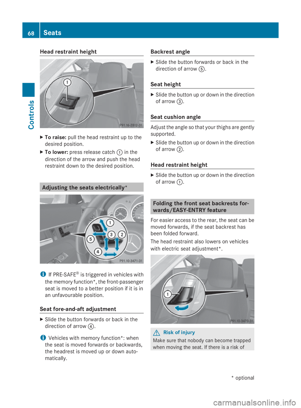
Head restraint height
X
To raise: pullthe headr estraint up to the
desired position.
X To lower: press release catch 0046in the
direction of the arrow and pusht he head
restraint downtot he desired position.Adjusting the seats electrically*
i
If PRE-SAFE ®
is triggere dinvehicles with
the memory function*, the front-passenger
seatism oved toabetter position if it is in
an unfavourable position.
Seat fore-and-aft adjustment X
Slid ethe button forwards or back in the
direction of arrow 0088.
i Vehicles with memory function*: when
the seatism oved forwards or backwards,
the headrest is moved up or downa uto-
matically. Backrest angle X
Slid ethe button forwards or back in the
direction of arrow 0086.
Seat height X
Slid ethe button up or downint he direction
of arrow 008A.
Seat cushion angle Adjust the angle so that yourt
highs are gently
supported.
X Slid ethe button up or downint he direction
of arrow 0047.
Head restraint height X
Slid ethe button up or downint he direction
of arrow 0046. Folding the front seat backrests for-
wards/EASY-ENTRY feature
For easier access to the rear, the seatc an be
moved forwards, if the seatb ackrest has
been folde dforward.
The headr estraint alsol owers on vehicles
with electric seata djustment*. G
Risk of injury
Make sure that nobody can become trapped
when moving the seat. If there is arisk of 68
SeatsControls
*o
ptional
207_AKB; 2; 3, en-GB
mkalafa,
Version: 2.11.8.1 2009-07-23T10:23:49+02:00-Seite 68
Page 73 of 313

0046
To raise the backrest contour
0047 To soften the backrest contour
008A To lower the backrest contour
0088 To harden the backrest contour
i When the door is unlocked, opened or the
key is in position 1in the ignition lock, the
setting of the lumbar support is automati-
cally checked and, if necessary, the indi-
vidual setting is restored. Multicontour seat*
You can adjust the contour of the fronts eat
backrest sindividually to provide optimum
support for your back. 0046
To adjust the thigh cushion
0047 To adjust the backrest contour in the lum-
bar region
008A To adjust the backrest contour in the
upper back region
0088 To adjust the backrest side cushions X
Make sure the key is in position 2in the
ignition lock. AIRSCARF* (Cabriolet)
The AIRSCARF neck-level heating function
blows warm air around the heads of car occu-
pants. The warm air flows out of the holes in
the head restraints. G
Risk of injury
Very hot air can flow out of the ventsint he
head restraints when AIRSCARF is in opera-
tion. This can cause burns on unprotected
skin near the vents. Lower the heating output
in good time, when necessary.
The three red indicator lamps in the button
indicate the heating level you have selected. X
Make sure that the key is in position 2in
the ignition lock.
X To activate: press button 0046.
Three red indicator lamps in the button light
up. The blower start supafterapreheating
phase of seven seconds.
X Press button 0046repeatedly until the
desired heating level is set.
X To switch off: press button0046repeatedly
until all indicator lamps go out.
You can use the adjustable fins on the head
restraint to adjust the height of the curren tof
air blown out accordin gtoyour height.
Make sure that there are no object scovering
the intak egrille on the back of the driver's
seat backrest. 70
SeatsControls
*o
ptional
207_AKB; 2; 3, en-GB
mkalafa,
Version: 2.11.8.1 2009-07-23T10:23:49+02:00-Seite 70
Page 75 of 313

G
Risk of accident
Only adjust the steering wheel whe nthe vehi-
cle is stationar yand do not pull away unti lthe
steering wheel adjustment mechanism is
locke dinposition. Otherwise, yo umight drive
withou tthe steering wheel adjustment mech-
anism being locke dinposition and be distrac-
ted from roa dand traffi cconditions by an
unexpecte dmovement of the steering wheel
and cause an accident.
However, the steerability of the vehicle is not
affected.
Whe nyou adjust the steering wheel ,make
sure that:
R the steering wheel can be reached with
your arm sslightl ybent
R yo uc an move your legs freely
R yo uc an see al lthe display sinthe instru-
ment cluster clearly Adjusting the steering wheel man-
ually 0046
Releas elever
0047 Height adjustment
008A Fore-and-aft adjustment
X Push release catch 0046dow ncompletely.
The steering column is unlocked.
X Adjus tthe steering wheel to the desired
position.
X Push release lever 0046up completely.
The steering wheel is locke dinposition. Adjusting the steering wheel electri-
cally*
0046
Height adjustment
0047 Fore-and-aft adjustment
You can find more information under:
R EASY-ENTRY/EXIT feature (Y page 72)
R storing settings (Y page 75) EASY-ENTRY/EXI
Tfeature*
The EASY-ENTRY/EXIT feature make sgetting
in and ou tofyourv ehicle easier.
The steering wheel swings upwards when
you:
R remove the key from the ignition lock
R ope nthe driver' sdoorw hent he key is in
position 0or 1in the ignition lock
Whe nthe key is inserted into the ignition lock
with the driver' sdoorc losed, the steering
wheel is automaticall ymovedtot he previ-
ously set position. G
Risk of injury
Make sure that nobody can become trapped
whe nyou activate the EASY-ENTRY/EXIT fea-
ture.
If there is ariskofs omeone becoming trap-
ped ,stop the adjustment procedure. To halt
the procedure: 72
Steering wheelControls
*o
ptional
207_AKB
;2;3,en-GB
mkalafa ,V ersion: 2.11.8.1
2009-07-23T10:23:49+02:00
-Seite 72
Page 143 of 313

One or more segments light up as the vehicle
approaches an obstacle, depending on the
vehicle's distance to the obstacle.
From the:
R
sixth segment onwards, you will hear an
intermittent warning tone for approx-
imately two seconds.
R seventh segment onwards, you will hear a
warning tone for approximately two sec-
onds. You have reached the minimum dis-
tance.
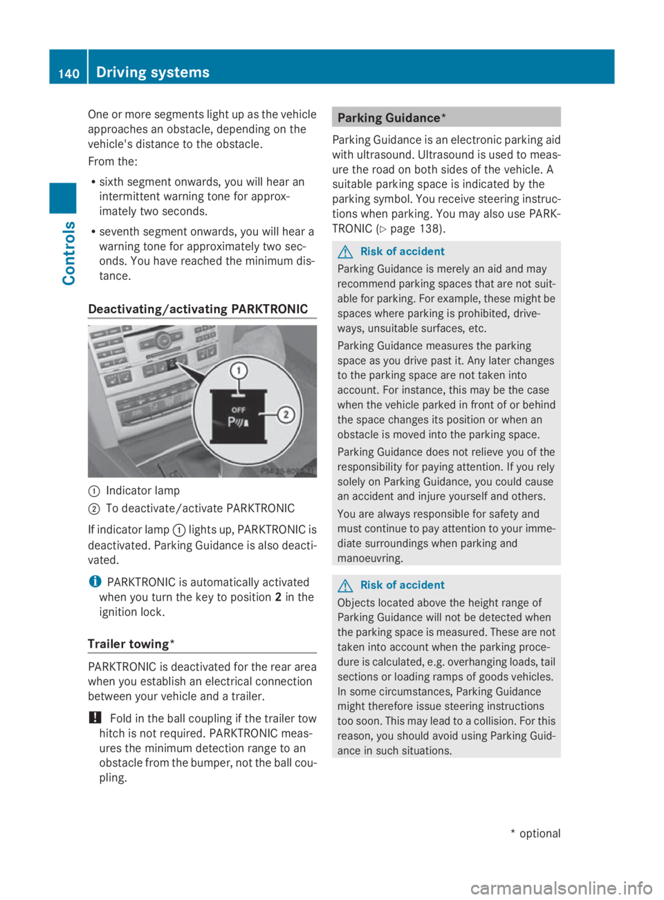
Deactivating/activating PARKTRONIC 0046
Indicator lamp
0047 To deactivate/activate PARKTRONIC
If indicator lamp 0046lights up, PARKTRONIC is
deactivated. Parking Guidance is also deacti-
vated.
i PARKTRONIC is automaticallya ctivated
when you turn the key to position 2in the
ignition lock.
Trailer towing* PARKTRONIC is deactivated for the rear area
when you establish an electrical connection
between your vehicle and atrailer.
! Fold in the ball coupling if the trailer tow
hitch is not required.P ARKTRONIC meas-
ures the minimum detection range to an
obstacle from the bumper, not the ball cou-
pling. Parking Guidance*
Parking Guidance is an electronic parking aid
with ultrasound. Ultrasound is used to meas-
ure the road on both sides of the vehicle. A
suitablep arking space is indicated by the
parking symbol. You receive steering instruc-
tions when parking. You may also use PARK-
TRONIC (Y page 138). G
Risk of accident
Parking Guidance is merely an aid and may
recommend parking spaces that are not suit-
able for parking. For example, these might be
spaces where parking is prohibited, drive-
ways, unsuitables urfaces, etc.
Parking Guidance measures the parking
space as you drive past it. Any later changes
to the parking space are not taken into
account. For instance, this may be the case
when the vehicle parked in front of or behind
the space changes its position or when an
obstacle is moved into the parking space.
Parking Guidance does not relieve you of the
responsibility for paying attention. If you rely
solely on Parking Guidance, you could cause
an accident and injure yourselfa nd others.
You are always responsible for safety and
must continue to pay attention to your imme-
diate surroundings when parking and
manoeuvring. G
Risk of accident
Objects located above the height range of
Parking Guidance will not be detected when
the parking space is measured. These are not
taken into account when the parking proce-
dure is calculated, e.g. overhanging loads, tail
sections or loading ramps of goods vehicles.
In some circumstances, Parking Guidance
might therefore issue steering instructions
too soon. This may lead to acollision. For this
reason, you should avoid using Parking Guid-
ance in such situations. 140
Driving systemsControls
*o
ptional
207_AKB;2;3,e
n-GB
mkalafa, Version: 2.11.8.1 2009-07-23T10:23:49+02:00-Seite 140
Page 185 of 313

X
Lower the bonnet and let it fall from a
heightofa pproximately 20 cm.
X Check that the bonnet has engage dprop-
erly.
i If the bonnet can be raiseds lightly, it is
not properl yengaged. Open it again and
close it with alittle more force. Engine oil
Depending on driving style, the vehicle con-
sumes up to 0.8 loil per 1,000 km. The oil
consumption may be highert han this when
the vehicle is new or if you frequently drive at
high engine speeds.
Checking the engine oil level Before checking the engine oil level the fol-
lowing conditions for the vehicle shouldbe
met:
R
the vehicle shouldbep arked on level
ground.
R the engine shouldbes witched off for at
least five minutes if the engine is at normal
operating temperature.
R the engine shouldbes witched off for at
least 30 minutes if the engine is not at
operating temperature (i.e. if you only start
the engine briefly).
Depending on the engine, the oil dipstick may
be installed at adifferent location. E3
50 (example) X
Pullo il dipstick 0046out of the oil dipstick
tube.
X Wipe off oil dipstick 0046.
X Insert oil dipstick 0046into the oil dipstick
tube to the stop, and take it out again.
The oil level is correct if the level is between
the minimum mark 008Aand maximum
mark 0047.
X Top up the oil if necessary.
Topping up the engine oil H
Environmental note
When topping up the oil, take care not to spill
any. Oil must not be allowed to escape into
the soil or waterways. You would otherwis ebe
damaging the environment. Cap (example)
X Turn cap 0046anti-clockwise and remove.
X Top up with the amount of oil required
(Y page 288).
i The difference in quantity betwee nthe
minimum mark and maximu mmark is
approximately 2litres.
i On vehicle switha4-cylinder petrol
engine and vehicle swith an 8-cylinder pet-
rol engine, the difference betwee nthe MIN
mark and the MAX mark is approximately
1.5 litres.
! Do not add too much oil. If too much oil
is added and the oil level is above the max- 182
Engine compartmentOperation
207_AKB; 2; 3, en-GB
mkalafa
,V ersion: 2.11.8.1
2009-07-23T10:23:49+02:00
-Seite 182
Page 197 of 313

X
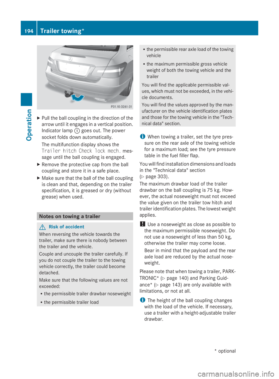
Pull the ball coupling in the direction of the
arrow until it engages in avertical position.
Indicator lamp 0046goes out. The power
socket folds down automatically.
The multifunction display shows the
Trailer hitch Check lock mech. mes-
sage until the ball coupling is engaged.
X Remove the protective cap from the ball
coupling and store it in asafe place.
X Make sure that the ball of the ball coupling
is clean and that, depending on the trailer
specification, it is greased or dry (without
grease) when used. Notes on towing
atrailer G
Risk of accident
When reversin gthe vehicle towards the
trailer, make sure there is nobody between
the trailer and the vehicle.
Couple and uncouple the trailer carefully. If
you do not couple the trailer to the towing
vehicle correctly, the trailer could become
detached.
Make sure that the following values are not
exceeded:
R the permissible trailer drawbar noseweight
R the permissible trailer load R
the permissible rear axle load of the towing
vehicle
R the maximum permissible gross vehicle
weight of both the towing vehicle and the
trailer
You will find the applicable permissible val-
ues, which must not be exceeded, in the vehi-
cle documents.
You will find the values approved by the man-
ufacturer on the vehicle identification plates
and those for the towing vehicle in the "Tech-
nical data" section.
i When towing atrailer, set the tyre pres-
sure on the rear axle of the towing vehicle
for am aximum load; see the tyre pressure
table in the fuel filler flap.
You will find installation dimensions and loads
in the "Technical data" section
(Y page 303).
The maximum drawbar load of the trailer
drawbar on the ball coupling is 75 kg. How-
ever, the actual noseweight must not exceed
the value given on the trailer tow hitch and
trailer identification plates. The lowest weight
applies.
! Use anoseweight as close as possible to
the maximum permissible noseweight. Do
not use anoseweight of less than 50 kg,
otherwise the trailer may come loose.
Bear in mind that the payloa dand the rear
axle load are reduced by the actual nose-
weight.
Please notet hat when towing atrailer, PARK-
TRONIC* (Y page 140) and Parking Guid-
ance* (Y page 143) are only availabl ewith
limitations ,ornot at all.
i The height of the ball coupling changes
with the load of the vehicle. If necessary,
use atrailer with aheight-adjustable trailer
drawbar. 194
Trailer towing*Operation
*optional
207_AKB; 2; 3, en-GB
mkalafa,
Version: 2.11.8.1 2009-07-23T10:23:49+02:00-Seite 194
Page 210 of 313

Vehicl
etoolkit and "Minispare"
emergenc yspare wheel*
The vehicl etool kit and "Minispare" emer-
genc yspare whee letc. ar eloc ate dint he
stowag ewellu nderneath the boot floor.
The vehicl etool kit contains:
R TIREFIT kit
R electri cairpump
R towing eye
R spare fuses
Vehicles with a"Minispare" emergency spare
wheel* have additional whee lchanging tools,
consisting of:
R centring pin
R jack
R one pair of gloves
R folding whee lchock
R whee lwrench G
Ris
kofi njury
The jack is designed onl ytoraise and hol dthe
vehicl efor as hort time whil eawheelis being
changed.
Yo um ustu se stands if yo uare carrying out
work on the vehicle.
Make sure tha tthe jack is place donafirm,
non-slip ,lev el surface. Do not us ewooden
blocks or similar objects as ajack underlay.
Otherwise, the jack will not be able to achieve
its load-bearing capacity du etothe restricted
height.
Do not start the engine at any time whil ea
whee lisbeing changed.
Do not li eunder the vehicl ewhenitisb eing
supporte dbythe jack. If yo udonot raise the
vehicl easd escribed, it could slip off the jack
(e.g. if the engine is started or if adoorort he
boot li disopenedorc losed)and yo ucould be
seriously injured. i
Whe nusing the jack, yo ushoul dalso
observe the safety notes in the "Flat tyre"
section ( Ypage 270).
X Ope nthe boot floor (Y page 171).
Vehicles with aTIREFI Tkit i
For vehicles with aTIREFIT kit, yo ucan
also purchase atyrec hanging tool kit*
(Y page 207). 0046
Centring pin
0047 Jack
008A One pair of gloves
0088 Cabriolet: straps for emergency release
of the sof ttop
0086 TIREFIT kit
0087 Electric ai rpump
006E Towing eye
006F Folding whee lchock
0070 Wheel wrench Where will
Ifind...?
207Practical advice
*optional
207_AKB; 2; 3, en-GB
mkalafa,
Version: 2.11.8.1 2009-07-23T10:23:49+02:00-Seite 207 Z