Page 132 of 521
WARNING!
If the hood is not fully latched, it could fly up when
the vehicle is moving and block your forward vision.
Be sure all hood latches are fully latched before
driving.
LIGHTS
Multifunction Lever
The multifunction lever controls the operation of the
headlights, turn signals, headlight beam selection, instru-
ment panel light dimming, passing light, interior
courtesy/dome lights, and optional fog lights. The mul-
tifunction lever is located on the left side of the steering
wheel.
Headlights and Parking Lights
Turn the end of the multifunction lever to the first detent
for parking light operation. Turn to the second detent for
headlight operation. Turn to the third detent for AUTO
headlight operation (if equipped).
Headlight Switch
130 UNDERSTANDING THE FEATURES OF YOUR VEHICLE
Page 138 of 521
NOTE:
•Turning on the high beam headlights turns off the fog
lights.
•A front fog light is a lighting device that provides
illumination in front of the vehicle under conditions of
fog, rain, snow, or dust. The front fog lights supple-
ment the lower beam of a standard headlight system.
•Proper aim and adjustment of the front fog lights
should be made to prevent excessive glare for other
drivers.
Turn Signals
Move the multifunction lever up or down, and the
arrows on each side of the instrument cluster will flash to
show proper operation of the left and right turn signal
lights. You can signal a lane change by moving the
multifunction lever partially up or down.Turn Signal Auto-Mode
Tap the multifunction lever once, and the turn signal (left
or right) will flash three times and automatically turn off.
Turn Signal Control
136 UNDERSTANDING THE FEATURES OF YOUR VEHICLE
Page 139 of 521

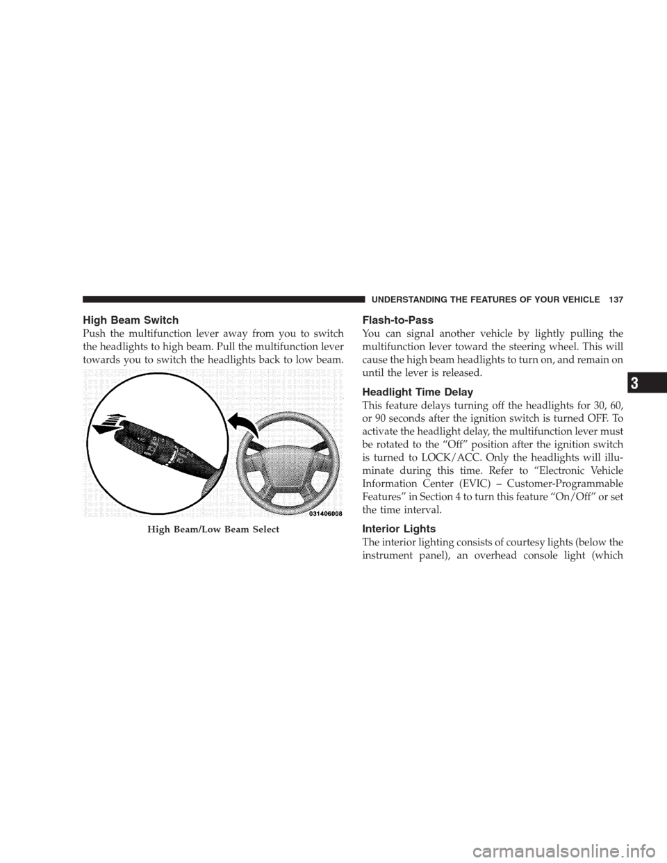
High Beam Switch
Push the multifunction lever away from you to switch
the headlights to high beam. Pull the multifunction lever
towards you to switch the headlights back to low beam.
Flash-to-Pass
You can signal another vehicle by lightly pulling the
multifunction lever toward the steering wheel. This will
cause the high beam headlights to turn on, and remain on
until the lever is released.
Headlight Time Delay
This feature delays turning off the headlights for 30, 60,
or 90 seconds after the ignition switch is turned OFF. To
activate the headlight delay, the multifunction lever must
be rotated to the “Off” position after the ignition switch
is turned to LOCK/ACC. Only the headlights will illu-
minate during this time. Refer to “Electronic Vehicle
Information Center (EVIC) – Customer-Programmable
Features” in Section 4 to turn this feature “On/Off” or set
the time interval.
Interior Lights
The interior lighting consists of courtesy lights (below the
instrument panel), an overhead console light (which
High Beam/Low Beam Select
UNDERSTANDING THE FEATURES OF YOUR VEHICLE 137
3
Page 157 of 521

WARNING!
•Your motorized door or gate will open and close
while you are training the Universal Transceiver.
Do not train the transceiver if people or pets are in
the path of the door or gate. Only use this trans-
ceiver with a garage door opener that has a “stop
and reverse” feature as required by federal safety
standards. This includes most garage door opener
models manufactured after 1982. Do not use a
garage door opener without these safety features.
Call toll-free 1–800–355–3515 or, on the Internet at
www.HomeLink.com for safety information or as-
sistance.
•Vehicle exhaust contains carbon monoxide, a dan-
gerous gas. Do not run your vehicle in the garage
while training the transceiver. Exhaust gas can
cause serious injury or death.
Programming HomeLink�
Before You Begin
If you have not trained any of the HomeLink�buttons,
erase all channels before you begin training.
To do this, press and hold the two outside buttons for up
to 20 seconds. The EVIC will display “CLEARING
CHANNELS.” Release the buttons when the EVIC mes-
sage states “CHANNELS CLEARED.”
It is recommended that a new battery be placed in the
hand-held transmitter of the device being programmed
to HomeLink�for more efficient training and accurate
transmission of the radio-frequency signal.
Your vehicle should be parked outside of the garage
while training.
1. Turn the ignition switch to the ON/RUN position.
UNDERSTANDING THE FEATURES OF YOUR VEHICLE 155
3
Page 187 of 521

WARNING!
Driving a vehicle with the red brake light on is
dangerous. Part of the brake system may have failed.
It will take longer to stop the vehicle. You could have
an accident. Have the vehicle checked immediately.
Vehicles equipped with the Anti-Lock Brake System
(ABS), are also equipped with Electronic Brake Force
Distribution (EBD). In the event of an EBD failure, the
Brake Warning Light will turn on along with the ABS
Light. Immediate repair to the ABS system is required.
Operation of the Brake Warning Light can be checked by
turning the ignition switch from the OFF position to the
ON position. The light should illuminate for approxi-
mately two seconds. The light should then turn off unless
the parking brake is applied or a brake fault is detected.
If the light does not illuminate, have the light inspected
by an authorized dealer.The light also will turn on when the parking brake is
applied with the ignition switch in the ON position.
NOTE:This light shows only that the parking brake is
applied. It does not show the degree of brake application.
3. Turn Signal Indicator
The arrows will flash with the exterior turn signals
when the turn signal lever is operated. A tone will
chime if the turn signals are left on for more than one
mile (2 km).
4. High Beam Indicator
Indicates that headlights are on high beam.
5. Malfunction Indicator Light (MIL)
The Malfunction Indicator Light (MIL) is part of
an onboard diagnostic system called OBD II that
monitors engine and automatic transmission con-
trol systems. The light will illuminate when the key is in
UNDERSTANDING YOUR INSTRUMENT PANEL 185
4
Page 197 of 521
Electronic Vehicle Information Center (EVIC)
Displays
When the appropriate conditions exist, the Electronic
Vehicle Information Center (EVIC) displays the following
messages:
•TURN SIGNAL ON
•PERFORM SERVICE
•DAMAGED KEY — KEY DOES NOT COMMUNI-
CATE
•KEY NOT PROGRAMMED — KEY NOT PRO-
GRAMMED
•WRONG KEY — KEY DOES NOT BELONG TO
VEHICLE
•KEY NOT PROGRAMMED — EXCEEDED KEY PRO-
GRAM LIMIT
•PROGRAMMING ACTIVE — NEW KEY PRO-
GRAMMED
•SERVICE SECURITY KEY
•DRIVER/PASSENGER DOOR OPEN (with graphic)
•LEFT/RIGHT REAR DOOR OPEN (with graphic)
•X DOORS OPEN (with graphic)
•LIFTGATE OPEN (with graphic)
•LIFTGATE/DOOR OPEN (with graphic)
•LIFTGATE/DOORS OPEN (with graphic)
•LIFTGLASS OPEN (with graphic)
•HOOD OPEN (with graphic)
•HOOD/DOOR OPEN (with graphic)
•HOOD/DOORS OPEN (with graphic)
UNDERSTANDING YOUR INSTRUMENT PANEL 195
4
Page 206 of 521

feature may be selected with or without the “Flash
Lamps with Lock” feature. To make your selection, press
and release the FUNCTION SELECT button until YES (Y)
or NO (N) appears.
Flash Lamps with Lock
When YES (Y) is selected, the front and rear turn signals
will flash when the doors are locked or unlocked with the
RKE transmitter. This feature may be selected with or
without the “Sound Horn with Lock” feature. To make
your selection, press and release the FUNCTION SE-
LECT button until YES (Y) or NO (N) appears.
Headlamp Off Delay
When this feature is selected, the driver can choose to
have the headlights remain on for 0, 30, 60, or 90 seconds
when exiting the vehicle. To make your selection, press
and release the FUNCTION SELECT button until “0,”
“30,” “60,” or “90” appears.
Automatic High Beams (Available with SmartBeam
Only)
When this feature is selected, the high beam headlights
will deactivate automatically under certain conditions. To
make your selection, press and release the FUNCTION
SELECT button until YES (Y) or NO (N) appears. Refer to
“Lights/SmartBeams — If Equipped” in Section 3 of this
manual for more information.
Headlights On with Wipers (Available with Auto
Headlights Only)
When YES (Y) is selected, and the headlight switch is in
the AUTO position, the headlights will turn on approxi-
mately 10 seconds after the wipers are turned on. The
headlights will also turn off when the wipers are turned
off if they were turned on by this feature. To make your
selection, press and release the FUNCTION SELECT
button until YES (Y) or NO (N) appears.
204 UNDERSTANDING YOUR INSTRUMENT PANEL
Page 350 of 521

A tire pressure monitoring sensor is located in the spare
wheel, if the vehicle is equipped with a matching full-size
spare wheel and tire assembly. The matching full-size
spare tire can be used in place of any of the four road
tires. A low spare tire will not cause the Tire Pressure
Monitoring Telltale Light to illuminate, a warning mes-
sage to appear, or the chime to sound.
The Tire Pressure Monitoring Telltale Light will
illuminate in the instrument cluster, a “TIRE LOW
PRESSURE” message will display in the instru-
ment cluster for 60 seconds, and an audible chime will be
activated, when one or more of the four active road tire
pressures are low. Should this occur, you should stop as
soon as possible, check the inflation pressure of each tire
on your vehicle, and inflate each tire to the vehicle’s
recommended cold placard pressure value. The system
will automatically update and the Tire Pressure Monitor-
ing Telltale Light will extinguish, once the updated tirepressures have been received. The vehicle may need to be
driven for up to 20 minutes above 15 mph (24 km/h) to
receive this information.
The Tire Pressure Monitoring Telltale Light will flash on
and off for 75 seconds, and remain on solid when a
system fault is detected. In addition, a “CHECK TPM
SYSTEM” message will be displayed for 75 seconds when
a system fault is detected, and a chime will sound. If the
ignition key is cycled, this sequence will repeat, provid-
ing the system fault still exists. The Tire Pressure Moni-
toring Telltale Light will turn off when the fault condition
no longer exists. A system fault can occur by any of the
following:
1. Jamming due to electronic devices or driving next to
facilities emitting the same Radio Frequencies as the TPM
sensors.
2. Installing some form of aftermarket window tinting
that affects radio wave signals.
348 STARTING AND OPERATING