2009 JAGUAR XF Miles
[x] Cancel search: MilesPage 181 of 391

181
Fuel and refuelling
FUEL CONSUMPTION
The fuel consumption figures shown below have been calculated using a standard testing
procedure (the new EC test proc edure from Directive 99/100/EC), and produced in accordance with
The Passenger Car Fuel Cons umption (Amendment) Order 1996.
Under normal use, a vehicle's actu al fuel consumption figures may differ from those achieved
through the test procedure, de pending on driving technique, ro ad and traffic conditions,
environmental factors, ve hicle load and condition.
Urban cycle
The urban test cycle is carried out from a cold start and cons ists of a series of accelerations,
decelerations and periods of stea dy speed driving and engine idling. The maximum speed attained
during the test is 50 km/h (30 mph) with an average speed of 19 km/h (12 mph).
Extra-urban cycle
The extra-urban test cycle is carried out immediatel y after the urban test. Approximately half of the
test comprises steady-speed driving, while the re mainder consists of a series of accelerations,
decelerations and engine idling . The maximum test speed is 120 km/h (75 mph) and the average
speed 63 km/h (39 mph). The test is carried out over a distance of 7 km (4.3 miles).
Combined
The combined figure is an average of the urban an d extra-urban test cycle results, which has been
weighted to take account of the differ ent distances covered during the two tests.
For additional information on fuel consumption figures and exhaust emissions, visit the Vehicle
Certification Agency (VCA) website at http://www.vcacarfueldata.org.uk/.
Variant
Urban Extra-urban Combined CO² emissions
g/km
3.0 V6 Diesel 9.5 l/100 km (30.0 mpg)5.5 l/100 km
(51.3 mpg) 6.8 l/100 km
(42.0 mpg) 179
3.0 V6 Petrol 15.8 l/100 km (17.8 mpg)7.5 l/100 km
(37.8 mpg) 10.5 l/100 km
(26.8 mpg) 249
5.0 V8 Petrol -
Normally aspirated 17.3 l/100 km
(46.3 mpg) 7.8 l/100 km
(36.4 mpg) 11.1 l/100 km
(25.4 mpg) 264
5.0 V8 Petrol - Supercharged 18.7 l/100 km
(15.1 mpg) 8.7 l/100 km
(32.4 mpg) 12.5 l/100 km
(22.5 mpg) 292
Page 224 of 391

Wheels and tyres
224
RUN FLAT TYRES
Run-flat tyres can be identified by the lettering
RSC on the sidewall. The tyre construction
utilises a specially reinforced sidewall, which
allows the vehicle to be driven at restricted
speeds, even when the tyre is depressurised.
Run-flat tyres can only be fitted to special rims,
constructed for ru n-flat tyre use.
A tyre pressure monitoring system is
mandatory when the vehicle is fitted with
run-flat tyres. See TYRE PRESSURE
MONITORING SYSTEM (page 234).
If the tyre has deflated, the vehicle should be
driven with caution, as handling characteristics
will be different compared to a fully inflated
tyre.
If the vehicle is fully la den with passengers and
luggage, the maximum di stance that can be
completed on a fully deflated tyre, is
approximately 80 kilo metres (50 miles).
Stop immediately if the tyre construction
begins to break down or if the tyre dislodges
from the wheel rim. Typi cally, this will be
accompanied by excessive vibration.
A tyre driven in a defl ated condition must be
replaced as s oon as possible. Vehicles fitted with run-flat tyres are not fitted
with a spare wheel or jacking equipment.
Therefore, run-flat tyre
s should be replaced
with the same type of tyre.
TOOL KIT
Tool kit contents
1. Jack.
2. Wheel brace.
3. Chock.
4. Locking wheel nut adaptor.
5. Towing eye.
Note: When returning the tool kit to its stowage
position, hook the T-bar of the clamp over the
jack handle, to se cure in position.
Note: The jack requi res occasional
maintenance. Examine the jack for wear,
damage or corrosion and lubricate the moving
parts.
WARNING
If a run-flat tyre is deflated, maximum
vehicle speed must not exceed
80 km/h (50 mph).
E91708
WARNING
After use, the tool kit should be
returned to the under floor storage
area and correctly stowed. Do not
leave the tool kit or it s components loose in the
storage area, as they can prove hazardous
during an impact or sudden manoeuvre.
E95183
5
1
34
2
Page 230 of 391

Wheels and tyres
230
Jaguar tyre repair kit safety information
WARNINGS
Some tyre damage may only be
partially sealed, or may not seal at all,
depending on the amount and type of
damage. Any loss of tyre pressure can
seriously affect vehicle safety.
Do not use the tyre repair kit if the tyre
has been damaged by driving while
under-inflated.
Only use the tyre repair kit to seal
damage located within the tyre tread
area.
Do not use the tyre repair kit to seal
damage to the tyre sidewall.
Do not exceed 80 km/h (50 mph)
when a repaired tyre is fitted to the
vehicle.
The maximum distan ce that should
be driven when a repaired tyre is
fitted, is 200 km (125 miles).
When a repaired tyre is fitted, drive
with caution and avoid sudden
braking or steering manoeuvres.
Only use the tyre repair kit for the
vehicle with which it was supplied.
Do not use the tyre repair kit for any
other purpose than tyre repair.
Never leave the tyre repair kit
unattended when in use.
Only use the tyre repair kit within the
-30 °C to +70 °C temperature range.
Always keep children and animals at a
safe distance from the tyre repair kit
when in use.
Do not stand dire ctly beside the
compressor when it is operating.Check the tyre sidewall prior to
inflation. If any cracks, damage or
deformities are apparent, do not
inflate the tyre.
Watch the tyre sidewall during
inflation. If any cracks, bumps or
similar damage, or deformities
appear, switch off the compressor and deflate
the tyre.
WARNINGS
Page 233 of 391

233
Wheels and tyres
9.Unless the vehicle is in an enclosed area,
start the engine.
10. Set the compressor switch to the on ( I)
position.
11. Inflate the tyre to a minimum of 1.9 bar
(26 lbf/in²) and a maximum of 3.5 bar
(51 lbf/in²).
•When pumping the sealant through the
tyre valve, the pressure may rise up to 6
bar (87 lbf/in²). The pressure will drop
again after approximately 30 seconds.
12. During the inflation, switch the
compressor off briefly, to check the tyre
pressure using the gauge mounted on the
compressor.
• It should not take longer than seven
minutes to inflate the tyre. If, after seven
minutes, the tyre has not yet reached
minimum pressure, the tyre should not
be used.
13. Once the tyre has been inflated, switch off
the compressor. If desired, the engine may
be turned off after the compressor has
been turned off.
14. Remove the power connector from the
auxiliary power socket.
15. Remove the inflation hose from the tyre
valve, by unscrewing it as quickly as
possible (count er-clockwise).
16. Replace the inflation hose protective cap
and the tyre valve cap.
17. Do not remove the sealant bottle from the
receiver.
18. Ensure that the tyre repair kit (including
the bottle and receiver caps) are placed
securely in the vehicle. You will need to
use the kit to check the tyre pressure after
approximately 3 km (2 miles), so ensure
they are easily accessible. 19.
Immediately drive the vehicle for
approximately 3 km (2 miles), to allow the
sealant to coat the inner surface of the tyre
and form a seal at the puncture.
Checking the tyre pressure after a repair
1.Drive the vehicle for 3 km (2 miles) then
stop in a safe place. Carry out a visual
examination of the tyres condition.
2. Make sure that the sealant container
section is in its original position.
3. Screw the inflation hos e connector firmly
onto the tyre valve.
4. Read the tyre pressure from the gauge.
5. If the pressure of the sealant filled tyre is
above 1.3 bar (19 lb/in²) adjust the
pressure to the correct value. See TYRE
CARE (page 217).
6. Ensure that the compressor switch is in
the off (O ) position and insert the power
cable connector into the auxiliary power
socket.
If the vehicle is in a well ventilated area,
start the engine.
WARNINGS
When driving the vehicle, if you
experience vibr ations, abnormal
steering, or noises, reduce speed
immediately. Drive with extreme caution and
reduced speed, to the first safe place to stop
the vehicle. Visually examine the tyre and
check its pressure. If there are any signs of
damage or deformity to the tyre, or the tyre
pressure is below 1.3 bar (19 lb/in²), do not
continue driving.
Consult a tyre repair centre or your
Dealer/Authorised Repairer, for
advice concerning the replacement of
a tyre after using a tyre repair kit.
Page 256 of 391

Vehicle recovery
256
TOWING THE VEHICLE ON FOUR
WHEELS
Note: The recommended recovery method is
to raise all four wheels.
Towing procedure
1. The vehicle should be parked on firm level
ground, with the parking brake on, and the
gear selector in P (Park).
2. Secure the towing attachment from the
recovery vehicle to the front towing eye.
See TOWING POINTS (page 253).
3. Dock the Jaguar Smart Key and switch on
the ignition. See GENERAL INFORMATION
(page 132). 4.
Apply the foot brake and release the
parking brake.
5. With the foot brake st ill applied, activate
the Emergency Park Release (EPR).
See TRANSPORTING THE VEHICLE
(page 254).
6. The vehicle can now be towed a maximum
of 0.8 km (0.5 miles) at a maximum speed
of 48 kmh (30 mph).
7. Upon arrival at the destination, ensure
wherever possible that the vehicle is
parked on firm level ground.
8. Lower the Emergency Park Release (EPR)
lever, to cancel EP R and to re-engage P
(Park).
9. Apply the parking brake.
10. Switch off the ignition and remove the
Jaguar Smart Key.
11. Remove the towing attachment from the
towing eye.
WARNINGS
Ensure that the remote control
remains docked whilst the vehicle is
being towed. Removing the remote
control will engage the steering lock, which
will prevent the vehicle from steering
correctly.
If the engine cannot be run whilst the
vehicle is being towed, there will be
no power assistance for the steering
or brakes. This will result in greater effort
being required to steer or slow the vehicle, and
greatly increased stopping distances.
CAUTIONS
The vehicle should only be towed in a
forward direction with all four wheels on
the ground.
The vehicle should only be towed for a
maximum of 0.8 km (0.5 miles), at a
maximum speed of 48 km/h (30 mph). Towing
for a greater distance or at a higher speed, may
result in serious damage to the transmission.
CAUTION
Leaving the ignition switched on for
extended periods will cause the battery
to drain.
WARNING
Use extreme caution when detaching
towing equipment. Vehicle movement
is possible which can result in serious
injuries.
Page 321 of 391

321
Telephone
HANDS-FREE CONTROLS
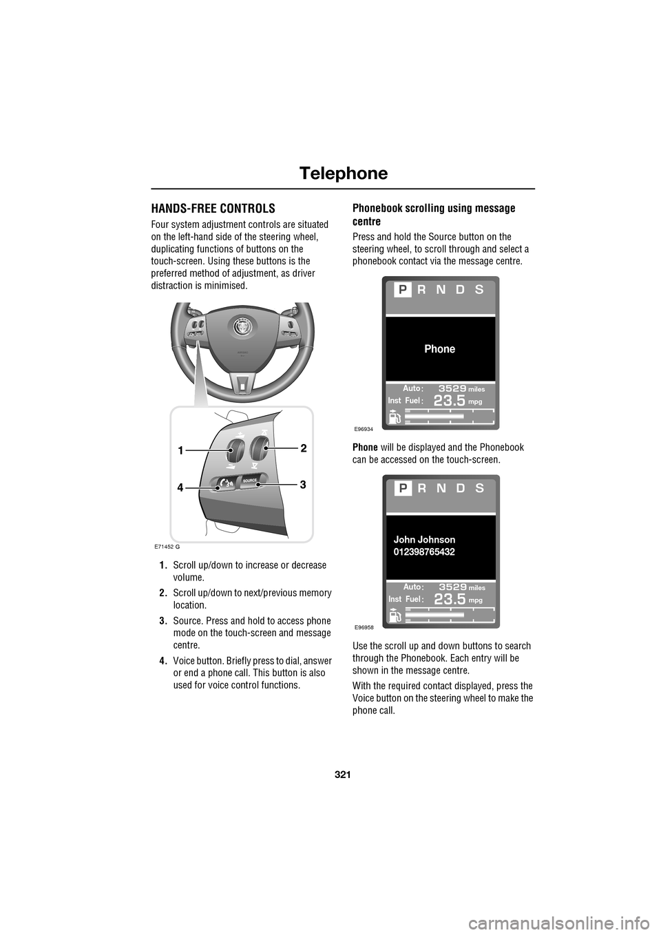
Four system adjustment controls are situated
on the left-hand side of the steering wheel,
duplicating functions of buttons on the
touch-screen. Using these buttons is the
preferred method of adjustment, as driver
distraction is minimised.
1. Scroll up/down to increase or decrease
volume.
2. Scroll up/down to ne xt/previous memory
location.
3. Source. Press and hold to access phone
mode on the touch-screen and message
centre.
4. Voice button. Briefly press to dial, answer
or end a phone call. This button is also
used for voice control functions.
Phonebook scrolling using message
centre
Press and hold the Source button on the
steering wheel, to scroll through and select a
phonebook contact via the message centre.
Phone will be displayed and the Phonebook
can be accessed on the touch-screen.
Use the scroll up and down buttons to search
through the Phonebook. Each entry will be
shown in the message centre.
With the required contact displayed, press the
Voice button on the steering wheel to make the
phone call.
E71452
Automiles
Inst Fuelmpg
Phone
E96934
Automiles
Inst Fuelmpg
John Johnson
012398765432
E96958
Page 340 of 391

Navigation system
340
MEASUREMENT UNITS
Distances are shown on the screen and given in
voice guidance, either in metric units
(kilometres and metres) or in Imperial units
(miles and yards) and can only be changed
from the vehicle touch-screen menu, not from
the navigation system menu.
To change the measur ement units, select
Vehicle on the vehicle touch screen, then select
Unit Change .
To change the units: The unit choices are
selected by touching either km or Mls.
KEYBOARD LAYOUT
The keyboard layout ca n be changed from a
QWERTY type to ABC DEF type, from the User
Settings screen, accessible from the
Navigation Setup screen.
Touch the bar to change the keyboard layout,
then touch OK.
Display set
Preferences
Button audio
Mls. MPH MPG km km/h 1/100
VehicleF
C
0
0
Display language English UKVol. presetsChange
JOL4657ENG
Navigation Setup
Selection
Calibration
RestoreUser
Settings
Defaults Quick POI
12 : 26 pm
RDS-TMC
Language
Selection
12 : 26 pm
Low Fuel Warning
User Settings
Display Petrol Station POI
Text Size on the MAP
Key board layout
Medium
OK
Default
ABC
JOL4658ENG
LUTON
LUTON
Menu
12 : 26 pm
Stored
Destination
Auto Voice
Entry
Guidance Off
Locations
Navigation SetupRoute Options
Page 342 of 391

Navigation system
342
MAP DISPLAY ICONS
The icons on the split screens are:This is only displayed when
a satellite signal is not being
received.
This icon is displayed when
TMC is selected and a signal
is received.
When the bar is across the
TMC, then a signal is not
being received and TMC will
not function.
Touching this icon toggles it
with the N (North) icon (1).
The compass always points
North or else the vehicle
direction arrow always
points to the top of the map.
Distance and direction for
the next turn.
If the compass icon (6) is
showing, the vehicle
direction icon (8) is always
to the top of the map
irrespective of where North
is.
Example RDS-TMC Icon
(this one showing incident).
Go back one screen.
Touch to repeat last voice
instruction.
GPS
TMC
TMC
mi1.2
Example POI (this one
showing a fuel station).
This icon shows information
concerning journey distance
and the estimated time
remaining before arriving at
your destination.
It also indicates your journey from your
current position to the next waypoint or to
your destination. In th is example the journey
is to your destination, shown in the top of the
icon as the vehicle position arrow and a
pointer towards a red circle.
This icon shows distance
from your current position,
distance and direction to
way point 2.
This is your zoom button,
enabling you to alter the map
scale. The current level of
zoom is shown between the
two arrows (e.g. 2 miles).
You may also see a zoom
bar on the map.
This icon is toggled with the
compass (6). When this is
showing, North is always to
the top of the map.
This icon is visible when the
navigation screen has been
scrolled away from the
current vehicle position, so
that the vehicle (compass)
icon is no longer visible.
Touch the icon to re-centre
the screen on the current
vehicle position.
mi136
mi17
mi2
N