2009 INFINITI QX56 mirror
[x] Cancel search: mirrorPage 1996 of 4171
EXL-48
< COMPONENT DIAGNOSIS >
TURN SIGNAL LAMP CIRCUIT
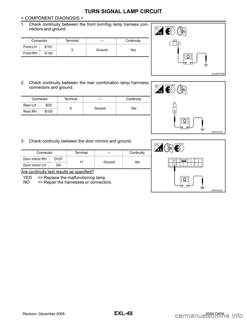
1. Check continuity between the front turn/fog lamp harness con-nectors and ground.
2. Check continuity between the rear combination lamp harnness connectors and ground.
3. Check continuity between the door mirrors and ground.
Are continuity test results as specified?
YES >> Replace the malfunctioning lamp.
NO >> Repair the harnesses or connectors.
Connector Terminal —Continuity
Front LH E101 3Gro un dY es
Front RH E102
ALLIA0721GB
Connector Terminal —Continuity
Rear LH B35 6Gro u nd Y es
Rear RH B105
WKIA4775E
Connector Terminal—Continuity
Door mirror RH D107 11Ground Yes
Door mirror LH D4
WKIA4525E
Revision: December 20092009 QX56
Page 2072 of 4171

EXL-124
< ECU DIAGNOSIS >
IPDM E/R (INTELLIGENT POWER DISTRIBUTION MODULE ENGINE ROOM)
Te r m i n a lWire
color Signal name Signal
input/
output Measuring condition
Reference value(Approx.)
Igni-
tion
switch Operation or condition
1 B/Y Battery power supply Input OFF —Battery voltage
2 R Battery power supply Input OFF —Battery voltage
3 BR ECM relay Output —Ignition switch ON or START
Battery voltage
Ignition switch OFF or ACC 0V
4 W/L ECM relay Output —Ignition switch ON or START
Battery voltage
Ignition switch OFF or ACC 0V
6L Throttle control motor
relay Output —Ignition switch ON or START
Battery voltage
Ignition switch OFF or ACC 0V
7 W/B ECM relay control Input — Ignition switch ON or START
0V
Ignition switch OFF or ACC Battery voltage
8 R/B Fuse 54 Output —Ignition switch ON or START
Battery voltage
Ignition switch OFF or ACC 0V
10 G Fuse 45 Output ONDaytime light system active
0V
Daytime light system inactive Battery voltage
11 Y/B A/C compressor Output ON or
START A/C switch ON or defrost A/C
switch
Battery voltage
A/C switch OFF or defrost A/C
switch 0V
12 L/W Ignition switch sup-
plied power Input —OFF or ACC
0V
ON or START Battery voltage
13 B/Y Fuel pump relay Output — Ignition switch ON or START
Battery voltage
Ignition switch OFF or ACC 0V
14 Y/R Fuse 49 Output —Ignition switch ON or START
Battery voltage
Ignition switch OFF or ACC 0V
15 LG/B Fuse 50 (VDC) Output — Ignition switch ON or START
Battery voltage
Ignition switch OFF or ACC 0V
15 GR Fuse 50 (ABS) Output — Ignition switch ON or START
Battery voltage
Ignition switch OFF or ACC 0V
16 G Fuse 51 Output —Ignition switch ON or START
Battery voltage
Ignition switch OFF or ACC 0V
17 W Fuse 55 Output —Ignition switch ON or START
Battery voltage
Ignition switch OFF or ACC 0V
19 W/R Starter motor Output START—Battery voltage
21 BR Ignition switch sup-
plied power
Input —OFF or ACC
0V
START Battery voltage
22 G Battery power supply Output OFF —Battery voltage
23 GR/W Door mirror defogger
output signal Output —When rear defogger switch is
ON
Battery voltage
When raker defogger switch is
OFF 0V
Revision: December 20092009 QX56
Page 2083 of 4171

EXTERIOR LIGHTING SYSTEM SYMPTOMSEXL-135
< SYMPTOM DIAGNOSIS >
C
DE
F
G H
I
J
K
M A
B
EXL
N
O P
Daytime light system does not activate. • Either high beam bulb
• Parking brake switch
• Combination switch
•BCM
• IPDM E/R
• Daytime light relay
• Harness between IPDM E/R
and daytime light relay. Daytime light system description.
Refer to
EXL-9, "System Descrip-
tion".
Front fog lamp is not
turned ON. One side
• Front fog lamp bulb
• Harness between IPDM E/R
and the front combination lamp
• Front combination lamp
• IPDM E/R Front fog lamp circuit
Refer to
EXL-38
.
Both sides Symptom diagnosis
"BOTH SIDE FRONT FOG LAMPS ARE NOT TURNED ON"
Refer to EXL-140
.
Parking lamp is not turned
ON. One side•Fuse
• Parking lamp bulb
• Harness between IPDM E/R
and the front/rear combination
lamp
• Front/rear combination lamp
• IPDM E/R Parking lamp circuit
Refer to
EXL-40
.
Both sides Symptom diagnosis
"PARKING, LICENSE PLATE AND TAIL LAMPS ARE NOT TURNED
ON"
Refer to EXL-139
.
Turn signal lamp does not
blink. Indicator lamp is nor-
mal.
(The applicable side
performs the high flash-
er activation).• Harness between BCM and
each turn signal lamp
• Turn signal lamp bulb
• Door mirror (if equipped with
turn signals in the door mirrors) Turn signal lamp circuit
Refer to
EXL-46
.
Turn signal indicator lamp
does not blink. One side
Combination meter —
Both sides
(Always) • Turn signal indicator lamp sig-
nal
• Combination meter
•BCM • Combination meter.
Data monitor "TURN IND".
• BCM (FLASHER)
Active test "FLASHER".
Both sides
(Does blink when acti-
vating the hazard warn-
ing lamp with the
ignition switch OFF) • The combination meter power
supply and the ground circuit
• Combination meter Combination meter
Power supply and the ground circuit
Refer to
MWI-30
.
Symptom
Possible causeInspection item
Revision: December 20092009 QX56
Page 2102 of 4171
EXL-154
< REMOVAL AND INSTALLATION >
PUDDLE LAMP
PUDDLE LAMP
Removal and InstallationINFOID:0000000005864680
REMOVAL
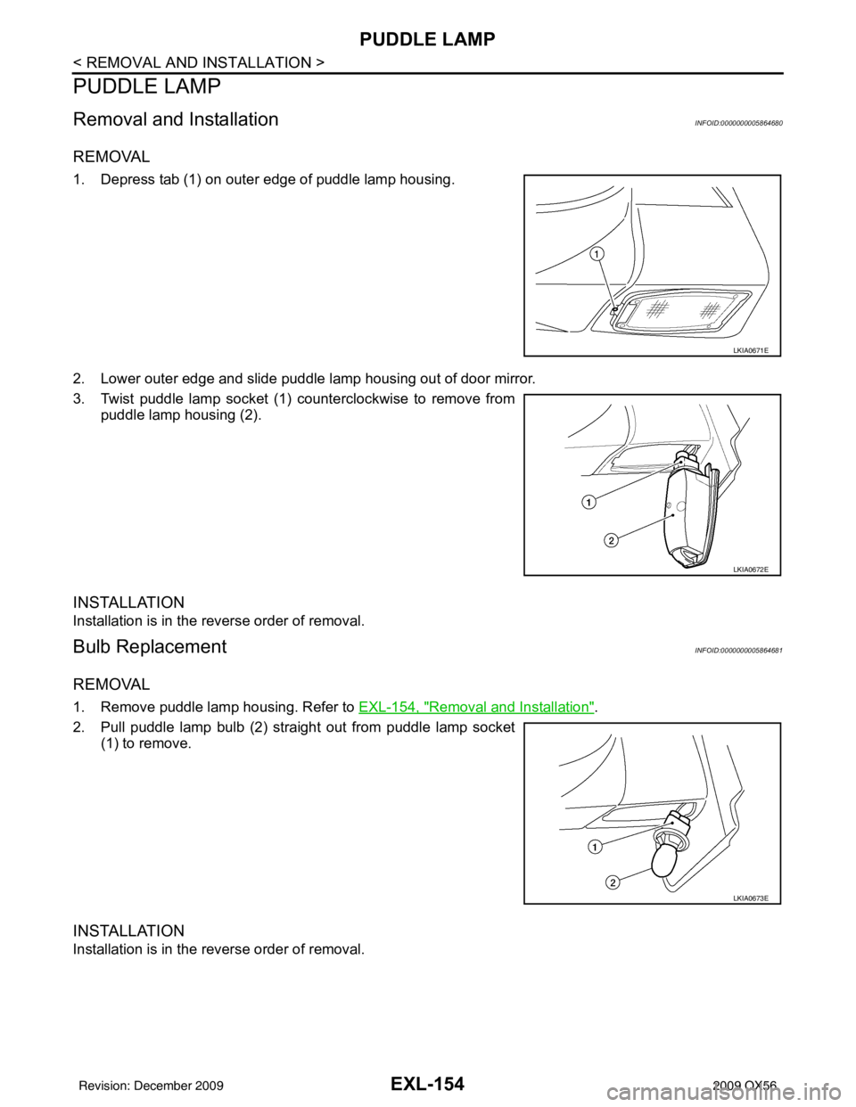
1. Depress tab (1) on outer edge of puddle lamp housing.
2. Lower outer edge and slide puddle lamp housing out of door mirror.
3. Twist puddle lamp socket (1) counterclockwise to remove frompuddle lamp housing (2).
INSTALLATION
Installation is in the reverse order of removal.
Bulb ReplacementINFOID:0000000005864681
REMOVAL
1. Remove puddle lamp housing. Refer to EXL-154, "Removal and Installation".
2. Pull puddle lamp bulb (2) straight out from puddle lamp socket (1) to remove.
INSTALLATION
Installation is in the reverse order of removal.
LKIA0671E
LKIA0672E
LKIA0673E
Revision: December 20092009 QX56
Page 2134 of 4171
EXT-28
< SERVICE INFORMATION >
DOOR OUTSIDE MOLDING
DOOR OUTSIDE MOLDING
Removal and InstallationINFOID:0000000003776115
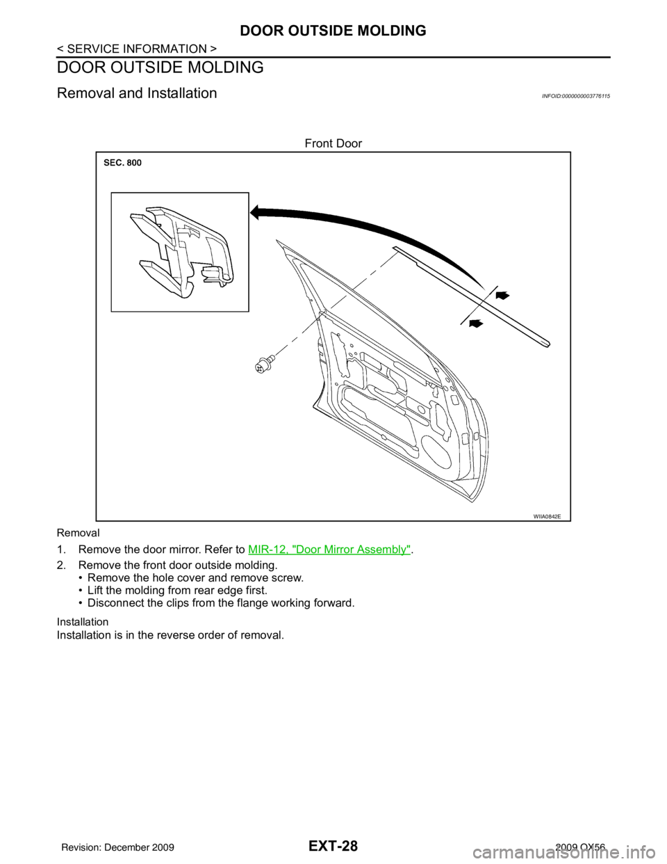
Front Door
Removal
1. Remove the door mirror. Refer to MIR-12, "Door Mirror Assembly".
2. Remove the front door outside molding. • Remove the hole cover and remove screw.
• Lift the molding from rear edge first.
• Disconnect the clips from the flange working forward.
Installation
Installation is in the reverse order of removal.
WIIA0842E
Revision: December 20092009 QX56
Page 2209 of 4171

RECOMMENDED CHEMICAL PRODUCTS AND SEALANTS
GI-15
< HOW TO USE THIS MANUAL >
C
D E
F
G H
I
J
K L
M B
GI
N
O PRECOMMENDED CHEMICAL PRODUCTS AND SEALANTS
Recommended Chemical Products and SealantsINFOID:0000000003771187
Refer to the following chart for help in selecting the appropriate chemical product or sealant.
Product Description PurposeNissan North America
Part No. (USA) Nissan Canada Part
No. (Canada) Aftermarket Cross-
reference Part Nos.
1 Rear View Mirror Adhe-
sive Used to permanently re-
mount rear view mirrors to
windows.
999MP-AM000P 99998-50505
Permatex 81844
2 Anaerobic Liquid Gas-
ket For metal-to-metal flange
sealing.
Can fill a 0.38 mm (0.015
inch) gap and provide in-
stant sealing for most pow-
ertrain applications.
999MP-AM001P 99998-50503
Permatex 51813 and
51817
3 High Performance
Thread Sealant Provides instant sealing on
any threaded straight or
parallel threaded fitting.
(Thread sealant only, no
locking ability.)
• Do not use on plastic.
999MP-AM002P 999MP-AM002P Permatex 56521
4 Silicone RTV Gasket Maker
999MP-AM003P
(Ultra Grey)99998-50506
(Ultra Grey)Permatex Ultra Grey
82194;
Three Bond
1207,1215, 1216,
1217F, 1217G and
1217H
Nissan RTV Part No.
999MP-A7007
Gasket Maker for Maxima/
Quest 5-speed automatic
transmission
(RE5F22A) ––
Three Bond 1281B
or exact equivalent in
its quality
5 High Temperature,
High Strength Thread
Locking Sealant (Red)
Threadlocker
999MP-AM004P 999MP-AM004P Permatex 27200;
Three Bond 1360,
1360N, 1305 N&P,
1307N, 1335,
1335B, 1363B,
1377C, 1386B, D&E
and 1388
Loctite 648
6 Medium Strength
Thread Locking Seal-
ant (Blue) Threadlocker (service tool
removable)
999MP-AM005P 999MP-AM005P Permatex 24200,
24206, 24240,
24283 and 09178;
Three Bond 1322,
1322N, 1324 D&N,
1333D, 1361C,
1364D, 1370C and
1374
Revision: December 20092009 QX56
Page 2253 of 4171
WINDSHIELD GLASSGW-11
< ON-VEHICLE REPAIR >
C
DE
F
G H
I
J
L
M A
B
GW
N
O P
ON-VEHICLE REPAIR
WINDSHIELD GLASS
Removal and InstallationINFOID:0000000003775954
REMOVAL
1. Remove inside mirror. Refer to MIR-11, "Removal and Installation".
2. Partially remove the headlining (front edge). Refer to INT-17, "
Removal and Installation".
3. Remove cowl top cover. Refer to EXT-18, "
Removal and Installation".
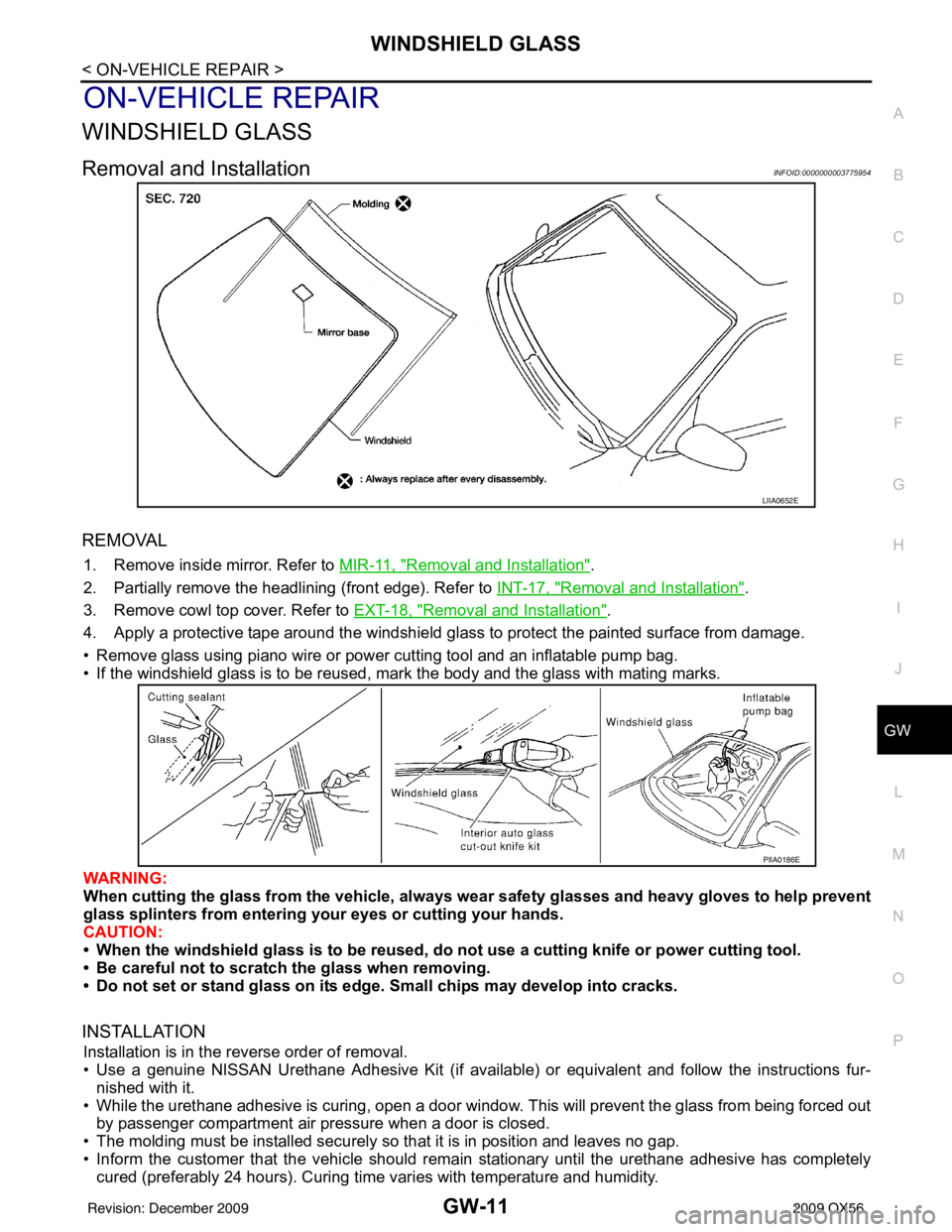
4. Apply a protective tape around the windshield gl ass to protect the painted surface from damage.
• Remove glass using piano wire or power cutting tool and an inflatable pump bag.
• If the windshield glass is to be reused, mark the body and the glass with mating marks.
WARNING:
When cutting the glass from the vehicle, always wear safety glasses and heavy gloves to help prevent
glass splinters from entering your eyes or cutting your hands.
CAUTION:
• When the windshield glass is to be reused, do not use a cutting knife or power cutting tool.
• Be careful not to scratch the glass when removing.
• Do not set or stand glass on its ed ge. Small chips may develop into cracks.
INSTALLATION
Installation is in the reverse order of removal.
• Use a genuine NISSAN Urethane Adhesive Kit (if availabl e) or equivalent and follow the instructions fur-
nished with it.
• While the urethane adhesive is curing, open a door window . This will prevent the glass from being forced out
by passenger compartment air pressure when a door is closed.
• The molding must be installed securely so that it is in position and leaves no gap.
• Inform the customer that the vehicle should rema in stationary until the urethane adhesive has completely
cured (preferably 24 hours). Curing time varies with temperature and humidity.
LIIA0652E
PIIA0186E
Revision: December 20092009 QX56
Page 2258 of 4171
GW-16
< ON-VEHICLE REPAIR >
FRONT DOOR GLASS AND REGULATOR
NOTE:
If any of the following work has been done, reset the power window motor limit switch.
• Removal and installation of the regulator assembly.
• Removal and installation of the power window motor from the regulator.
• Installation of a new glass window.
• Installation of a new glass run.
Check the label on the power window motor for the part number. If the power window motor part number
matches one of the following, the motor must be removed from the regulator and the limit switch reset using
the “INSTALLATION WITHOUT RESET SWITCH” procedure in “FRONT DOOR GLASS REGULATOR
ASSEMBLY”.
• 80730-ZT01A
• 80731-ZT01A
• 80730-ZM70B
• 80731-ZM70B
If the power window motor part number does not match one of the part numbers above, the limit switch can be
reset in the vehicle using the “INSTA LLATION WITH RESET SWITCH” procedure.
NOTE:
• The label can be checked with the power window motor in the vehicle by using a mirror.
• Some of the power window motors with the part num bers above may appear to have a reset switch, but it will
not reset the limit switch.
Fitting Inspection
• Check that the glass is securely fit into the glass run groove.
• Lower the glass slightly [approximately 10 to 20 mm (0 .39 to 0.79 in)] and check that the clearance to the
sash is parallel. If the clearance between the glass and sash is not parallel, loosen the regulator bolts, guide
rail bolts, and glass and guide rail bolts to correct the glass position.
FRONT DOOR GLASS REGULATOR
Removal
1. Remove the front door finisher. Refer to INT-11, "Removal and Installation".
2. Position the aside the vapor barrier.
3. Remove the hole cover over rear glass bolt.
4. Temporarily reconnect the power window switch.
5. Operate the power window main switch to raise/ lower the door window until the glass bolts can be seen.
6. Remove the glass bolts.
7. Raise the front door glass and hold it in place with suitable tool.
8. Disconnect the harness connector fr om the regulator assembly.
9. Remove the bolts and the regulator assembly.
Disassembly And Assembly
Remove the regulator motor from the regulator assembly.
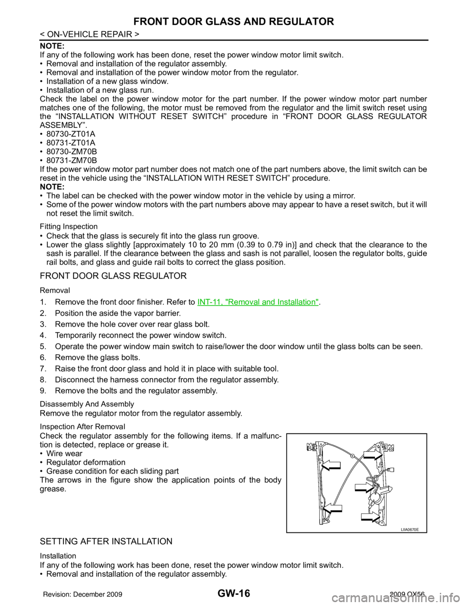
Inspection After Removal
Check the regulator assembly for the following items. If a malfunc-
tion is detected, replace or grease it.
• Wire wear
• Regulator deformation
• Grease condition for each sliding part
The arrows in the figure show the application points of the body
grease.
SETTING AFTER INSTALLATION
Installation
If any of the following work has been done, reset the power window motor limit switch.
• Removal and installation of the regulator assembly.
LIIA0670E
Revision: December 20092009 QX56