Page 805 of 4171
BOTH DOORS MIRROR DEFOGGER DON’T OPERATE BUT REAR WINDOW DEFOGGER OPERATES
DEF-37
< SYMPTOM DIAGNOSIS >
C
DE
F
G H
I
J
K
M A
B
DEF
N
O P
BOTH DOORS MIRROR DEFOGGER DON’T OPERATE BUT REAR WIN-
DOW DEFOGGER OPERATES
Diagnosis ProcedureINFOID:0000000003776358
1. CHECK INTERMITTENT INCIDENT
Check intermittent incident.
Refer to GI-38, "
Intermittent Incident".
Is the inspection result normal?
YES >> Check the following. • Battery power supply circuit.
• IPDM E/R.
NO >> Repair or replace the malfunctioning parts.
Revision: December 20092009 QX56
Page 806 of 4171
DEF-38
< SYMPTOM DIAGNOSIS >
DRIVER SIDE DOOR MIRROR DEFOGGER DOES NOT OPERATE.
DRIVER SIDE DOOR MIRROR DEFOGGER DOES NOT OPERATE.
Diagnosis ProcedureINFOID:0000000003776359
1. CHECK DOOR MIRROR DEFOGGER LH
Check door mirror defogger LH.
Refer to DEF-13, "
Component Function Check".
Is the inspection result normal?
YES >> Refer to GI-38, "Intermittent Incident".
NO >> Repair or replace the malfunctioning parts.
Revision: December 20092009 QX56
Page 807 of 4171
PASSENGER SIDE DOOR MIRROR DEFOGGER DOES NOT OPERATE.
DEF-39
< SYMPTOM DIAGNOSIS >
C
D E
F
G H
I
J
K
M A
B
DEF
N
O P
PASSENGER SIDE DOOR MIRROR DEFOGGER DOES NOT OPERATE.
Diagnosis ProcedureINFOID:0000000003776360
1. CHECK DOOR MIRROR DEFOGGER RH
Check door mirror defogger RH.
Refer to DEF-15, "
Component Function Check".
Is the inspection result normal?
YES >> Refer to GI-38, "Intermittent Incident".
NO >> Repair or replace the malfunctioning parts.
Revision: December 20092009 QX56
Page 956 of 4171
![INFINITI QX56 2009 Factory Service Manual DLK-144
< COMPONENT DIAGNOSIS >[WITH INTELLIGENT KEY SYSTEM]
HOMELINK UNIVERSAL TRANSCEIVER
Component Function Check
INFOID:0000000003775819
1.CHECK FUNCTION
Check that system receiver (garage door op INFINITI QX56 2009 Factory Service Manual DLK-144
< COMPONENT DIAGNOSIS >[WITH INTELLIGENT KEY SYSTEM]
HOMELINK UNIVERSAL TRANSCEIVER
Component Function Check
INFOID:0000000003775819
1.CHECK FUNCTION
Check that system receiver (garage door op](/manual-img/42/57031/w960_57031-955.png)
DLK-144
< COMPONENT DIAGNOSIS >[WITH INTELLIGENT KEY SYSTEM]
HOMELINK UNIVERSAL TRANSCEIVER
Component Function Check
INFOID:0000000003775819
1.CHECK FUNCTION
Check that system receiver (garage door opener, et c.) operates with original hand-held transmitter.
Is the inspection result normal?
YES >> GO TO 2
NO >> Receiver or hand-held transmitter is malfunctioning.
2.CHECK ILLUMINATION
1. Turn ignition switch “OFF”.
2. Press each of the transmitter buttons and watch for the red light
to illuminate with each button.
Is the inspection result normal?
YES >> GO TO 3
NO >> Refer to DLK-144, "
Diagnosis Procedure".
3.CHECK TRANSMITTER
Check transmitter with Tool*.
*:For details, refer to Technical Service Bulletin.
Is the inspection result normal?
YES >> Receiver or hand-held transmitter malfunction, not vehicle related.
NO >> Replace auto anti-dazzling inside mirror (homelink universal transceiver).
Diagnosis ProcedureINFOID:0000000003775820
1.CHECK POWER SUPPLY
1. Disconnect auto anti-dazzling inside mirror (homelink universal transceiver) connector.
2. Check voltage between auto anti-dazzling inside mirror (homelink universal transceiver) harness connector and ground.
Is the inspection result normal?
YES >> GO TO 2
NO >> Check the following. • 10A fuse [No. 19 located in the fuse block (J/B)]
• Harness for open or short between fuse and auto anti-dazzling inside mirror (homelink universaltransceiver).
PIIA4815E
ALKIA0659ZZ
Auto anti-dazzling inside mirror
(Homelink universal transceiver) connector Terminal Condition
Voltage (V)
(Approx.)
R7 10Ground Ignition switch position: LOCK Battery voltage
Revision: December 20092009 QX56
Page 957 of 4171
HOMELINK UNIVERSAL TRANSCEIVERDLK-145
< COMPONENT DIAGNOSIS > [WITH INTELLIGENT KEY SYSTEM]
C
D
E
F
G H
I
J
L
M A
B
DLK
N
O P
2.CHECK GROUND CIRCUIT
Check continuity between auto anti-dazzling inside mirror (homelink
universal transceiver) harness connector and ground.
Is the inspection result normal?
YES >> GO TO 3
NO >> Repair harness.
3.CHECK INTERMITTENT INCIDENT
Refer to GI-38, "
Intermittent Incident".
>> INSPECTION END.
ALKIA0660ZZ
Auto anti-dazzling inside mirror
(Homelink universal transceiver) connector Te r m i n a l
Ground Continuity
R7 8 Yes
Revision: December 20092009 QX56
Page 1851 of 4171

EM-28
< ON-VEHICLE REPAIR >
INTAKE MANIFOLD
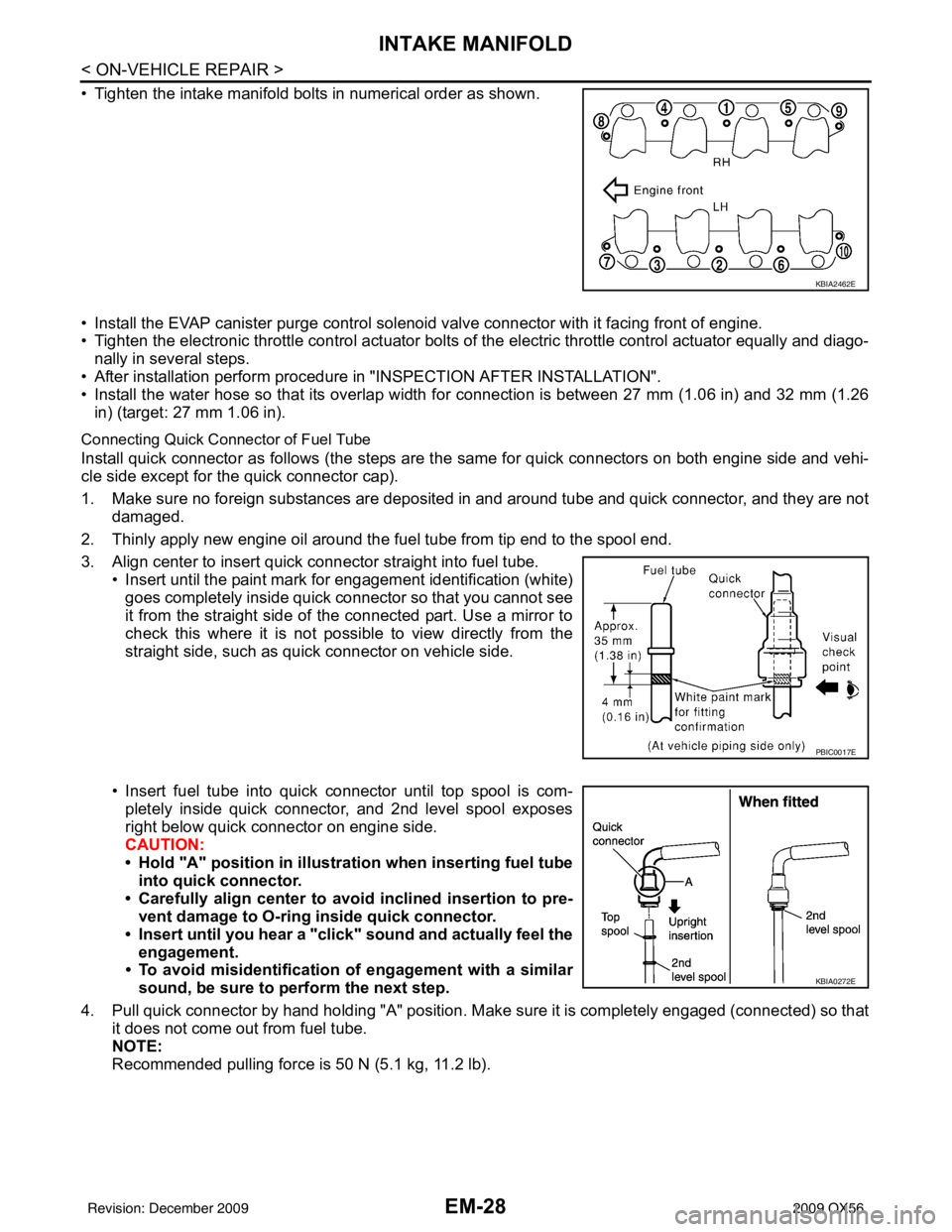
• Tighten the intake manifold bolts in numerical order as shown.
• Install the EVAP canister purge control solenoid valve connector with it facing front of engine.
• Tighten the electronic throttle control actuator bolts of the electric throttle control actuator equally and diago-
nally in several steps.
• After installation perform procedure in "INSPECTION AFTER INSTALLATION".
• Install the water hose so that its overlap width for connection is between 27 mm (1.06 in) and 32 mm (1.26 in) (target: 27 mm 1.06 in).
Connecting Quick Connector of Fuel Tube
Install quick connector as follows (the steps are t he same for quick connectors on both engine side and vehi-
cle side except for the quick connector cap).
1. Make sure no foreign substances are deposited in and around tube and quick connector, and they are not damaged.
2. Thinly apply new engine oil around the fuel tube from tip end to the spool end.
3. Align center to insert quick connector straight into fuel tube. • Insert until the paint mark for engagement identification (white)goes completely inside quick connector so that you cannot see
it from the straight side of the connected part. Use a mirror to
check this where it is not possible to view directly from the
straight side, such as quick connector on vehicle side.
• Insert fuel tube into quick connector until top spool is com- pletely inside quick connector, and 2nd level spool exposes
right below quick connector on engine side.
CAUTION:
• Hold "A" position in illustration when inserting fuel tubeinto quick connector.
• Carefully align center to avoid inclined insertion to pre-
vent damage to O-ring inside quick connector.
• Insert until you hear a "click" sound and actually feel the
engagement.
• To avoid misidentification of engagement with a similar
sound, be sure to pe rform the next step.
4. Pull quick connector by hand holding "A" position. Make sure it is completely engaged (connected) so that
it does not come out from fuel tube.
NOTE:
Recommended pulling force is 50 N (5.1 kg, 11.2 lb).
KBIA2462E
PBIC0017E
KBIA0272E
Revision: December 20092009 QX56
Page 1866 of 4171
FUEL INJECTOR AND FUEL TUBEEM-43
< ON-VEHICLE REPAIR >
C
DE
F
G H
I
J
K L
M A
EM
NP
O
Do not touch the engine imme
diately after stopping, as engine becomes extremely hot.
NOTE:
Use mirrors for checking on hidden points.
Revision: December 20092009 QX56
Page 1995 of 4171

TURN SIGNAL LAMP CIRCUITEXL-47
< COMPONENT DIAGNOSIS >
C
DE
F
G H
I
J
K
M A
B
EXL
N
O P
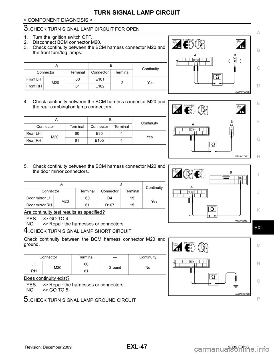
3.CHECK TURN SIGNAL LAMP CIRCUIT FOR OPEN
1. Turn the ignition switch OFF.
2. Disconnect BCM connector M20.
3. Check continuity between the BCM harness connector M20 and the front turn/fog lamps.
4. Check continuity between the BCM harness connector M20 and the rear combination lamp connectors.
5. Check continuity between the BCM harness connector M20 and the door mirror connectors.
Are continuity test results as specified?
YES >> GO TO 4.
NO >> Repair the harnesses or connectors.
4.CHECK TURN SIGNAL LAMP SHORT CIRCUIT
Check continuity between the BCM harness connector M20 and
ground.
Does continuity exist?
YES >> Repair the harnesses or connectors.
NO >> GO TO 5.
5.CHECK TURN SIGNAL LAMP GROUND CIRCUIT
AB Continuity
Connector Terminal Connector Terminal
Front LH M2060 E101
2Yes
Front RH 61 E102
ALLIA0722GB
AB Continuity
Connector Terminal Connector Terminal
Rear LH M2060 B35 4
Ye s
Rear RH 61 B105 4
WKIA4774E
AB
Continuity
Connector Terminal Connector Terminal
Door mirror LH M2060 D4 15
Ye s
Door mirror RH 61 D107 15
WKIA4524E
ConnectorTerminal—Continuity
LH M20 60
Ground No
RH 61
ALLIA0404GB
Revision: December 20092009 QX56