2009 INFINITI QX56 transmission oil
[x] Cancel search: transmission oilPage 3673 of 4171
A/T CONTROL SYSTEMTM-25
< FUNCTION DIAGNOSIS >
CEF
G H
I
J
K L
M A
B
TM
N
O P
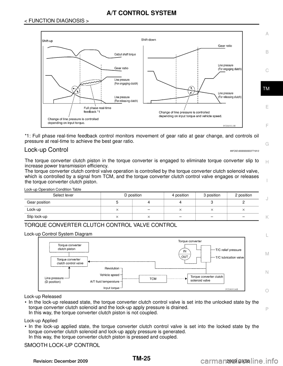
*1: Full phase real-time feedback control monitors move ment of gear ratio at gear change, and controls oil
pressure at real-time to achieve the best gear ratio.
Lock-up ControlINFOID:0000000003771813
The torque converter clutch piston in the torque conv erter is engaged to eliminate torque converter slip to
increase power transmission efficiency.
The torque converter clutch control valve operation is c ontrolled by the torque converter clutch solenoid valve,
which is controlled by a signal from TCM, and the to rque converter clutch control valve engages or releases
the torque converter clutch piston.
Lock-up Operation Condition Table
TORQUE CONVERTER CLUTCH CONTROL VALVE CONTROL
Lock-up Control System Diagram
Lock-up Released
In the lock-up released state, the torque converter clutch control valve is set into the unlocked state by the
torque converter clutch solenoid and the lock-up apply pressure is drained.
In this way, the torque converter clutch piston is not coupled.
Lock-up Applied
In the lock-up applied state, the torque converter clutch control valve is set into the locked state by the
torque converter clutch solenoid and lock-up apply pressure is generated.
In this way, the torque converter clutch piston is pressed and coupled.
SMOOTH LOCK-UP CONTROL
PCIA0013E
Select lever D position 4 position 3 position 2 position
Gear position 54432
Lock-up ×– ×××
Slip lock-up ××–––
PCIA0014E
Revision: December 20092009 QX56
Page 3716 of 4171

TM-68
< COMPONENT DIAGNOSIS >
P0745 PRESSURE CONTROL SOLENOID A
P0745 PRESSURE CONTROL SOLENOID A
DescriptionINFOID:0000000003771902
The line pressure solenoid valve regulates the oil pump discharge pressure to suit the driving condition in
response to a signal sent from the TCM.
The line pressure duty cycle value is not consistent when the closed throttle position signal is “ON”.
To confirm the line pressure duty cycle at low pressu re, the accelerator (throttle) should be open until
the closed throttle posi tion signal is “OFF”.
CONSULT-III Reference Value in Data Monitor ModeINFOID:0000000003771903
On Board Diagnosis LogicINFOID:0000000003771904
This is an OBD-II self-diagnostic item.
Diagnostic trouble code “P0745” with CONSULT-III is detected under the following conditions.
- When TCM detects an improper voltage drop when it tries to operate the solenoid valve.
- When TCM detects as irregular by comparing target value with monitor value.
Possible CauseINFOID:0000000003771905
Harness or connectors
(The solenoid circuit is open or shorted.)
Line pressure solenoid valve
DTC Confirmation ProcedureINFOID:0000000003771906
NOTE:
If “DTC Confirmation Procedure” has been previously performed, always turn ignition switch “OFF”
and wait at least 10 seconds before performing the next test.
After the repair, perform the following proc edure to confirm the malfunction is eliminated.
WITH CONSULT-III
1. Turn ignition switch “ON” and select “DATA MONITOR” mode for “ENGINE” with CONSULT-III.
2. Engine start and wait at least 5 second.
3. If DTC is detected, go to TM-68, "Diagnosis Procedure"
.
WITH GST
Follow the procedure “With CONSULT-III”.
Diagnosis ProcedureINFOID:0000000003771907
1.CHECK INPUT SIGNAL
With CONSULT-III
1. Turn ignition switch “ON”.
2. Select “MAIN SIGNALS” in “DATA MONITO R” mode for “TRANSMISSION” with CONSULT-III.
3. Start the engine.
4. Read out the value of “LINE PRES SOL” while driving.
OK or NG
OK >> GO TO 4.
NG >> GO TO 2.
2.CHECK TCM POWER SUPPLY AND GROUND CIRCUIT
Item name Condition Display value (Approx.)
LINE PRES SOL During driving 0.2 - 0.6 A
Item name Condition Display value (Approx.)
LINE PRES SOL During driving 0.2 - 0.6 A
Revision: December 20092009 QX56
Page 3768 of 4171

TM-120
< SYMPTOM DIAGNOSIS >
SYSTEM SYMPTOM
Check the starting system. Refer to STR-5, "Work Flow".
OK or NG
OK >> INSPECTION END
NG >> Repair or replace damaged parts.
In "P" Position, Vehi cle Moves When PushedINFOID:0000000003771993
SYMPTOM:
Even though the selector lever is set in the “P ” position, the parking mechanism is not actuated,
allowing the vehicle to be moved when it is pushed.
DIAGNOSTIC PROCEDURE
1.CHECK TRANSMISSION RANGE SWITCH CIRCUIT
Perform self-diagnosis. Refer to TM-32, "CONSULT-III Function (TRANSMISSION)"
.
Do the self-diagnosis results indicate transmission range switch?
YES >> Check the malfunctioning system. Refer to TM-44, "Diagnosis Procedure".
NO >> GO TO 2.
2.CHECK CONTROL CABLE
Check the control cable.
Refer to TM-195, "Checking of A/T Position"
.
OK or NG
OK >> GO TO 3.
NG >> Adjust control cable. Refer to TM-195, "Adjustment of A/
T Position".
3.CHECK A/T FLUID CONDITION
1. Remove oil pan. Refer to TM-201, "Oil Pan"
.
2. Check A/T fluid condition. Refer to TM-179, "Checking the A/T
Fluid (ATF)".
OK or NG
OK >> INSPECTION END
NG >> GO TO 4.
4.DETECT MALFUNCTIONING ITEM
Check the malfunction items. If any items are dam aged, repair or replace damaged parts. Refer to TM-152,
"Symptom Table" (Symptom No. 58).
OK or NG
OK >> INSPECTION END
NG >> Repair or replace damaged parts.
In "N" Position, Vehicle MovesINFOID:0000000003771994
SYMPTOM:
Vehicle moves forward or backwar d when selecting “N” position.
DIAGNOSTIC PROCEDURE
LCIA0345E
SCIA5199E
Revision: December 20092009 QX56
Page 3769 of 4171
SYSTEM SYMPTOMTM-121
< SYMPTOM DIAGNOSIS >
CEF
G H
I
J
K L
M A
B
TM
N
O P
1.CHECK TRANSMISSION RANGE SWITCH CIRCUIT
Perform self-diagnosis. Refer to TM-32, "CONSULT-III Function (TRANSMISSION)"
.
Do the self-diagnostic results indicate transmission range switch?
YES >> Check the malfunctioning system. Refer to TM-44, "Diagnosis Procedure".
NO >> GO TO 2.
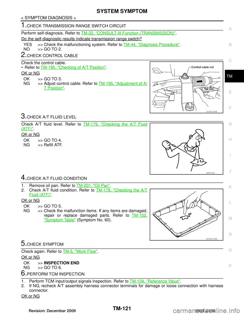
2.CHECK CONTROL CABLE
Check the control cable.
Refer to TM-195, "Checking of A/T Position"
.
OK or NG
OK >> GO TO 3.
NG >> Adjust control cable. Refer to TM-195, "Adjustment of A/
T Position".
3.CHECK A/T FLUID LEVEL
Check A/T fluid level. Refer to TM-179, "Checking the A/T Fluid
(ATF)".
OK or NG
OK >> GO TO 4.
NG >> Refill ATF.
4.CHECK A/T FLUID CONDITION
1. Remove oil pan. Refer to TM-201, "Oil Pan"
.
2. Check A/T fluid condition. Refer to TM-179, "Checking the A/T
Fluid (ATF)".
OK or NG
OK >> GO TO 5.
NG >> Check the malfunction items. If any items are damaged, repair or replace damaged parts. Refer to TM-152,
"Symptom Table" (Symptom No. 60).
5.CHECK SYMPTOM
Check again. Refer to TM-5, "Work Flow"
.
OK or NG
OK >> INSPECTION END
NG >> GO TO 6.
6.PERFORM TCM INSPECTION
1. Perform TCM input/output signals inspection. Refer to TM-104, "Reference Value"
.
2. If NG, recheck A/T assembly harness connector terminals for damage or loose connection with harness
connector.
OK or NG
LCIA0345E
SAT638A
SCIA5199E
Revision: December 20092009 QX56
Page 3771 of 4171
SYSTEM SYMPTOMTM-123
< SYMPTOM DIAGNOSIS >
CEF
G H
I
J
K L
M A
B
TM
N
O P
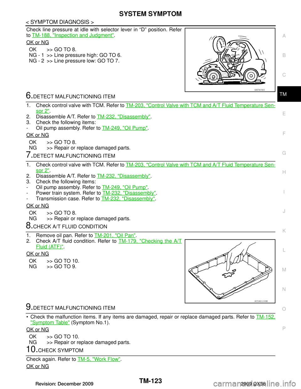
Check line pressure at idle with selector lever in “D” position. Refer
to TM-188, "Inspection and Judgment"
.
OK or NG
OK >> GO TO 8.
NG - 1 >> Line pressure high: GO TO 6.
NG - 2 >> Line pressure low: GO TO 7.
6.DETECT MALFUNCTIONING ITEM
1. Check control valve with TCM. Refer to TM-203, "Control Valve with TCM and A/T Fluid Temperature Sen-
sor 2".
2. Disassemble A/T. Refer to TM-232, "Disassembly"
.
3. Check the following items:
- Oil pump assembly. Refer to TM-249, "Oil Pump"
.
OK or NG
OK >> GO TO 8.
NG >> Repair or replace damaged parts.
7.DETECT MALFUNCTIONING ITEM
1. Check control valve with TCM. Refer to TM-203, "Control Valve with TCM and A/T Fluid Temperature Sen-
sor 2".
2. Disassemble A/T. Refer to TM-232, "Disassembly"
.
3. Check the following items:
- Oil pump assembly. Refer to TM-249, "Oil Pump"
.
- Power train system. Refer to TM-232, "Disassembly"
.
- Transmission case. Refer to TM-232, "Disassembly"
.
OK or NG
OK >> GO TO 8.
NG >> Repair or replace damaged parts.
8.CHECK A/T FLUID CONDITION
1. Remove oil pan. Refer to TM-201, "Oil Pan"
.
2. Check A/T fluid condition. Refer to TM-179, "Checking the A/T
Fluid (ATF)".
OK or NG
OK >> GO TO 10.
NG >> GO TO 9.
9.DETECT MALFUNCTIONING ITEM
Check the malfunction items. If any items are damaged, repair or replace damaged parts. Refer to TM-152,
"Symptom Table" (Symptom No.1).
OK or NG
OK >> GO TO 10.
NG >> Repair or replace damaged parts.
10.CHECK SYMPTOM
Check again. Refer to TM-5, "Work Flow"
.
OK or NG
SAT494G
SCIA5199E
Revision: December 20092009 QX56
Page 3773 of 4171

SYSTEM SYMPTOMTM-125
< SYMPTOM DIAGNOSIS >
CEF
G H
I
J
K L
M A
B
TM
N
O P
Refer to TM-186, "Inspection and Judgment".
OK or NG
OK >> GO TO 6.
OK in “1” position, NG in “R” position>>GO TO 5.
NG in both “1” and “R” positions>>GO TO 8.
5.DETECT MALFUNCTIONING ITEM
1. Disassemble A/T. Refer to TM-232, "Disassembly"
.
2. Check the following items:
- Reverse brake. Refer to TM-232, "Disassembly"
.
OK or NG
OK >> GO TO 9.
NG >> Repair or replace damaged parts.
6.CHECK LINE PRESSURE
Check the line pressure with the engine idling. Refer to TM-188,
"Inspection and Judgment".
OK or NG
OK >> GO TO 9.
NG - 1 >> Line pressure high. GO TO 7.
NG - 2 >> Line pressure low. GO TO 8.
7.DETECT MALFUNCTIONING ITEM
1. Check control valve with TCM. Refer to TM-203, "Control Valve with TCM and A/T Fluid Temperature Sen-
sor 2".
2. Disassemble A/T. Refer to TM-232, "Disassembly"
.
3. Check the following items:
- Oil pump assembly. Refer to TM-249, "Oil Pump"
.
OK or NG
OK >> GO TO 9.
NG >> Repair or replace damaged parts.
8.DETECT MALFUNCTIONING ITEM
1. Check control valve with TCM. Refer to TM-203, "Control Valve with TCM and A/T Fluid Temperature Sen-
sor 2".
2. Disassemble A/T. Refer to TM-232, "Disassembly"
.
3. Check the following items:
- Oil pump assembly. Refer to TM-249, "Oil Pump"
.
- Power train system. Refer to TM-232, "Disassembly"
.
- Transmission case. Refer to TM-232, "Disassembly"
.
OK or NG
OK >> GO TO 9.
NG >> Repair or replace damaged parts.
9.CHECK A/T FLUID CONDITION
1. Remove oil pan. Refer to TM-201, "Oil Pan"
.
SAT493G
SAT494G
Revision: December 20092009 QX56
Page 3776 of 4171
TM-128
< SYMPTOM DIAGNOSIS >
SYSTEM SYMPTOM
NG >> Repair or replace damaged parts.
7.DETECT MALFUNCTIONING ITEM
1. Check control valve with TCM. Refer to TM-203, "Control Valve with TCM and A/T Fluid Temperature Sen-
sor 2".
2. Disassemble A/T. Refer to TM-232, "Disassembly"
.
3. Check the following items:
- Oil pump assembly. Refer to TM-249, "Oil Pump"
.
- Power train system. Refer to TM-232, "Disassembly"
.
- Transmission case. Refer to TM-232, "Disassembly"
.
OK or NG
OK >> GO TO 8.
NG >> Repair or replace damaged parts.
8.CHECK A/T FLUID CONDITION
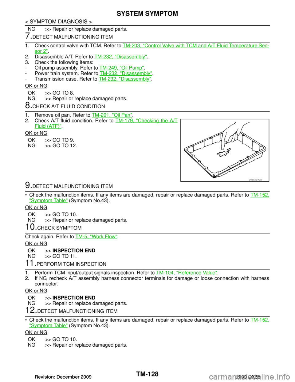
1. Remove oil pan. Refer to TM-201, "Oil Pan"
.
2. Check A/T fluid condition. Refer to TM-179, "Checking the A/T
Fluid (ATF)".
OK or NG
OK >> GO TO 9.
NG >> GO TO 12.
9.DETECT MALFUNCTIONING ITEM
Check the malfunction items. If any items are dam aged, repair or replace damaged parts. Refer to TM-152,
"Symptom Table" (Symptom No.43).
OK or NG
OK >> GO TO 10.
NG >> Repair or replace damaged parts.
10.CHECK SYMPTOM
Check again. Refer to TM-5, "Work Flow"
.
OK or NG
OK >> INSPECTION END
NG >> GO TO 11.
11 .PERFORM TCM INSPECTION
1. Perform TCM input/output signals inspection. Refer to TM-104, "Reference Value"
.
2. If NG, recheck A/T assembly harness connector terminals for damage or loose connection with harness
connector.
OK or NG
OK >> INSPECTION END
NG >> Repair or replace damaged parts.
12.DETECT MALFUNCTIONING ITEM
Check the malfunction items. If any items are dam aged, repair or replace damaged parts. Refer to TM-152,
"Symptom Table" (Symptom No.43).
OK or NG
OK >> GO TO 10.
NG >> Repair or replace damaged parts.
SCIA5199E
Revision: December 20092009 QX56
Page 3777 of 4171
SYSTEM SYMPTOMTM-129
< SYMPTOM DIAGNOSIS >
CEF
G H
I
J
K L
M A
B
TM
N
O P
Vehicle Cannot Be Started from D1INFOID:0000000003771998
SYMPTOM:
Vehicle cannot be started from D1 on cruise test - Part 1.
DIAGNOSTIC PROCEDURE
1.CONFIRM THE SYMPTOM
Check if vehicle creeps in “R” position.
OK or NG
OK >> GO TO 2.
NG >> Refer to TM-124, "Vehicle Does Not Creep Backward in "R" Position"
.
2.CHECK SELF-DIAGNOSTIC RESULTS
Perform self-diagnosis. Refer to TM-32, "CONSULT-III Function (TRANSMISSION)"
.
Is any malfunction detected by self-diagnostic results?
YES >> Check the malfunctioning system.
NO >> GO TO 3.
3.CHECK ACCELERATOR PEDA L POSITION(APP) SENSOR
Check accelerator pedal position (APP) sensor. Refer to TM-70, "Diagnosis Procedure"
.
OK or NG
OK >> GO TO 4.
NG >> Repair or replace accelerator pedal position (APP) sensor.
4.CHECK A/T FLUID LEVEL
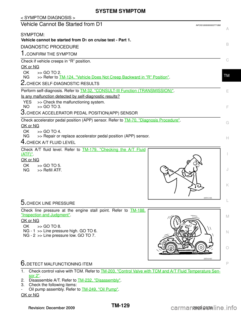
Check A/T fluid level. Refer to TM-179, "Checking the A/T Fluid
(ATF)".
OK or NG
OK >> GO TO 5.
NG >> Refill ATF.
5.CHECK LINE PRESSURE
Check line pressure at the engine stall point. Refer to TM-188,
"Inspection and Judgment".
OK or NG
OK >> GO TO 8.
NG - 1 >> Line pressure high. GO TO 6.
NG - 2 >> Line pressure low. GO TO 7.
6.DETECT MALFUNCTIONING ITEM
1. Check control valve with TCM. Refer to TM-203, "Control Valve with TCM and A/T Fluid Temperature Sen-
sor 2".
2. Disassemble A/T. Refer to TM-232, "Disassembly"
.
3. Check the following items:
- Oil pump assembly. Refer to TM-249, "Oil Pump"
.
OK or NG
SAT638A
SAT494G
Revision: December 20092009 QX56