Page 3172 of 4171

RSU-24
< REMOVAL AND INSTALLATION >
REAR LOAD LEVELING AIR SUSPENSION COMPRESSOR ASSEMBLY
REAR LOAD LEVELING AIR SUSPENSION COMPRESSOR ASSEMBLY
Removal and InstallationINFOID:0000000003772299
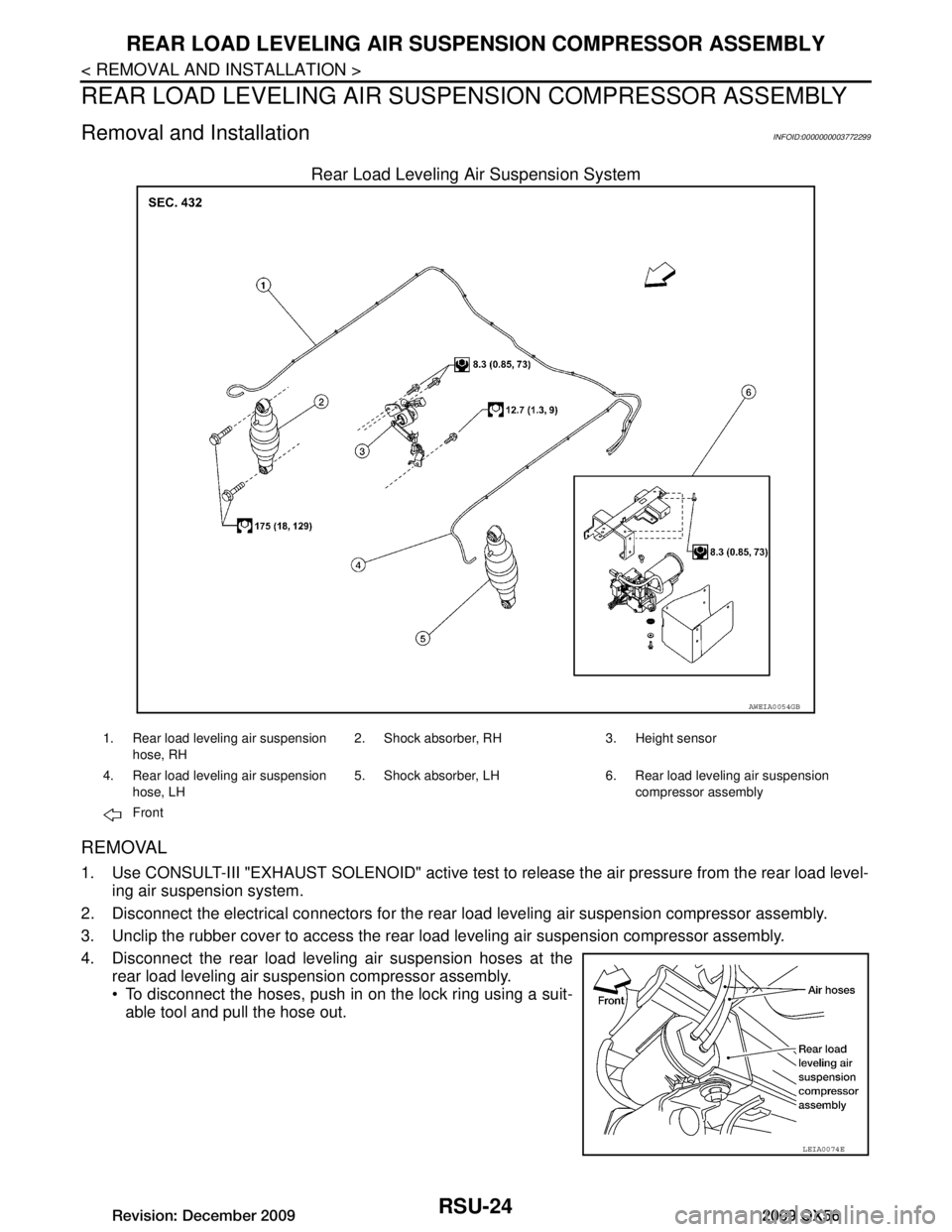
Rear Load Leveling Air Suspension System
REMOVAL
1. Use CONSULT-III "EXHAUST SOLENOID" active test to release the air pressure from the rear load level-
ing air suspension system.
2. Disconnect the electrical connectors for the rear load leveling air suspension compressor assembly.
3. Unclip the rubber cover to access the rear load leveling air suspension compressor assembly.
4. Disconnect the rear load leveling air suspension hoses at the rear load leveling air suspension compressor assembly.
To disconnect the hoses, push in on the lock ring using a suit-
able tool and pull the hose out.
AWEIA0054GB
1. Rear load leveling air suspension
hose, RH 2. Shock absorber, RH 3. Height sensor
4. Rear load leveling air suspension hose, LH 5. Shock absorber, LH 6. Rear load leveling air suspension
compressor assembly
Front
LEIA0074E
Revision: December 20092009 QX56
Page 3173 of 4171
REAR LOAD LEVELING AIR SUSPENSION COMPRESSOR ASSEMBLY
RSU-25
< REMOVAL AND INSTALLATION >
C
D F
G H
I
J
K L
M A
B
RSU
N
O P
5. Remove the four bolts that mount the rear load leveling air sus- pension compressor assembly to the underbody.
INSTALLATION
Installation is in the reverse order of removal.
To connect the rear load leveling air suspension hoses, the lockring must be fully seated in the fitt ing. Insert the hose (B) into the
lock ring (A) until the lock ring (A) is touching the hose (B) as
shown. Pull on the hose to check that it is securely inserted.
LEIA0090E
LEIA0078E
Revision: December 20092009 QX56
Page 3174 of 4171

RSU-26
< REMOVAL AND INSTALLATION >
CONTROL UNIT
CONTROL UNIT
Removal and InstallationINFOID:0000000003772300
REMOVAL
1. Remove the rear LH interior trim panel. Refer to INT-14, "Removal and Installation" .
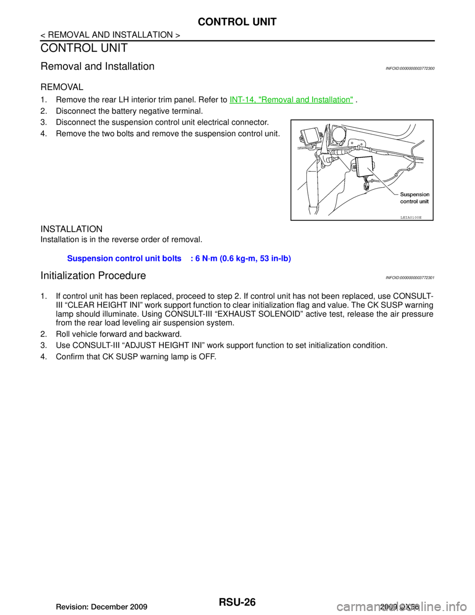
2. Disconnect the battery negative terminal.
3. Disconnect the suspension control unit electrical connector.
4. Remove the two bolts and remove the suspension control unit.
INSTALLATION
Installation is in the reverse order of removal.
Initialization ProcedureINFOID:0000000003772301
1. If control unit has been replaced, proceed to step 2. If control unit has not been replaced, use CONSULT-
III “CLEAR HEIGHT INI” work support function to clear initialization flag and value. The CK SUSP warning
lamp should illuminate. Using CONSULT-III “EXHAUST SOLENOID” active test, release the air pressure
from the rear load leveling air suspension system.
2. Roll vehicle forward and backward.
3. Use CONSULT-III “ADJUST HEIGHT INI” work support function to set initialization condition.
4. Confirm that CK SUSP warning lamp is OFF.
LEIA0100E
Suspension control unit bolts : 6 N·m (0.6 kg-m, 53 in-lb)
Revision: December 20092009 QX56
Page 3175 of 4171
HEIGHT SENSORRSU-27
< REMOVAL AND INSTALLATION >
C
DF
G H
I
J
K L
M A
B
RSU
N
O P
HEIGHT SENSOR
Removal and InstallationINFOID:0000000003772302
Rear Load Leveling Air Suspension System
REMOVAL
1. Use CONSULT-III “EXHAUST SOLENOID ” active test to release the air pressure from the rear load level-
ing air suspension system.
2. Disconnect the electrical connector for the height sensor.
3. Remove the two height sensor bolts and height sensor arm bracket bolt.
4. Remove the height sensor.
INSTALLATION
Installation is in the reverse order of removal.
AWEIA0054GB
1. Rear load leveling air suspension hose, RH 2. Shock absorber, RH 3. Height sensor
4. Rear load leveling air suspension hose, LH 5. Shock absorber, LH 6. Rear load leveling air suspension
compressor assembly
Front
LEIA0080E
Revision: December 20092009 QX56
Page 3176 of 4171
RSU-28
< REMOVAL AND INSTALLATION >
HEIGHT SENSOR
1. Start the engine.
2. Use CONSULT-III to perform "STANDARD HEIGHT LEVEL" work support function.
3. Using data monitor of CONSULT-III, verify "HEIGT CALC" is at 0 mm.
4. Check the vehicle height. Refer to RSU-30, "Wheelarch Height (Unladen*
1)" . If vehicle height is not
within ± 10 mm (0 ± 0.39 in) of the specification, perform the initialization procedure. Refer to RSU-26,
"Initialization Procedure".
Revision: December 20092009 QX56
Page 3177 of 4171

SERVICE DATA AND SPECIFICATIONS (SDS)
RSU-29
< SERVICE DATA AND SPECIFICATIONS (SDS)
C
D F
G H
I
J
K L
M A
B
RSU
N
O P
SERVICE DATA AND SPECIFICATIONS (SDS)
SERVICE DATA AND SPECIFICATIONS (SDS)
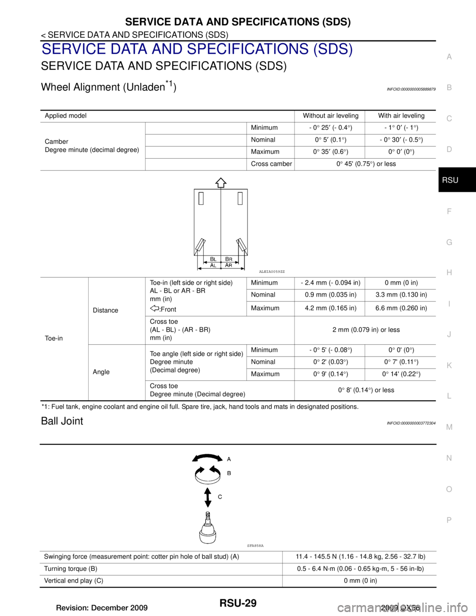
Wheel Alignment (Unladen*1)INFOID:0000000005889879
*1: Fuel tank, engine coolant and engine oil full. Spare tire, jack, hand tools and mats in designated positions.
Ball JointINFOID:0000000003772304
Applied model Without air leveling With air leveling
Camber
Degree minute (decimal degree) Minimum - 0
° 25 ′ (- 0.4 °)- 1 ° 0 ′ (- 1 °)
Nominal 0 ° 5 ′ (0.1 °)- 0 ° 30 ′ (- 0.5 °)
Maximum 0 ° 35 ′ (0.6 °)0 ° 0 ′ (0 °)
Cross camber 0 ° 45' (0.75 °) or less
To e - i n Distance
Toe-in (left side or right side)
AL - BL or AR - BR
mm (in)
:Front Minimum - 2.4 mm (- 0.094 in) 0 mm (0 in)
Nominal 0.9 mm (0.035 in) 3.3 mm (0.130 in)
Maximum 4.2 mm (0.165 in) 6.6 mm (0.260 in)
Cross toe
(AL - BL) - (AR - BR)
mm (in) 2 mm (0.079 in) or less
Angle Toe angle (left side or right side)
Degree minute
(Decimal degree) Minimum - 0
° 5' (- 0.08 °)0 ° 0' (0 °)
Nominal 0 ° 2' (0.03 °)0 ° 7' (0.11 °)
Maximum 0 ° 9' (0.14 °)0 ° 14' (0.22 °)
Cross toe
Degree minute (Decimal degree) 0
° 8' (0.14 °) or less
ALEIA0059ZZ
Swinging force (measurement point: cotter pin hole of ball stud) (A) 11.4 - 145.5 N (1.16 - 14.8 kg, 2.56 - 32.7 lb)
Turning torque (B) 0.5 - 6.4 N·m (0.06 - 0.65 kg-m, 5 - 56 in-lb)
Vertical end play (C) 0 mm (0 in)
SFA858A
Revision: December 20092009 QX56
Page 3178 of 4171
RSU-30
< SERVICE DATA AND SPECIFICATIONS (SDS)
SERVICE DATA AND SPECIFICATIONS (SDS)
Wheelarch Height (Unladen*
1)INFOID:0000000003772305
Unit: mm (in)
*1: Fuel, engine coolant and engine oil full. Spare tire, jack, hand tools and mats in designated positions.
*2: Verify the vehicle height. If vehicle height is not within ± 10 mm (0.39 in) of the specification, perform the control unit initialization pro-
cedure. Refer to RSU-26, "Initialization Procedure"
.
Suspension type
Air leveling*
2
Applied model2WD 4WD
Front wheelarch height (Hf) 920
(36.22) 937
(36.89)
Rear wheelarch height (Hr) 917
(36.10) 937
(36.89)
LEIA0085E
Revision: December 20092009 QX56
Page 3179 of 4171

SB-1
RESTRAINTS
C
DE
F
G
I
J
K L
M
SECTION SB
A
B
SB
N
O P
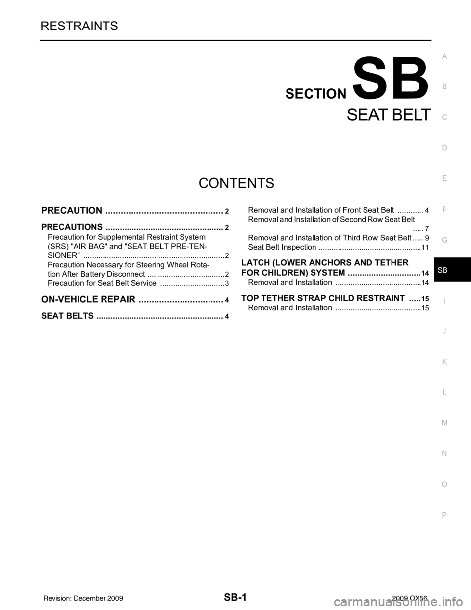
CONTENTS
SEAT BELT
PRECAUTION ....... ........................................2
PRECAUTIONS .............................................. .....2
Precaution for Supplemental Restraint System
(SRS) "AIR BAG" and "SEAT BELT PRE-TEN-
SIONER" ............................................................. ......
2
Precaution Necessary for Steering Wheel Rota-
tion After Battery Disconnect ............................... ......
2
Precaution for Seat Belt Service ...............................3
ON-VEHICLE REPAIR ..................................4
SEAT BELTS .......................................................4
Removal and Installation of Front Seat Belt ........ .....4
Removal and Installation of Second Row Seat Belt
.....
7
Removal and Installation of Third Row Seat Belt .....9
Seat Belt Inspection ............................................. ....11
LATCH (LOWER ANCHORS AND TETHER
FOR CHILDREN) SYSTEM ...............................
14
Removal and Installation .........................................14
TOP TETHER STRAP CHILD RESTRAINT .....15
Removal and Installation .........................................15
Revision: December 20092009 QX56