Page 1907 of 4171
EM-84
< DISASSEMBLY AND ASSEMBLY >
ENGINE UNIT
c. Push the piston and connecting rod assembly out to the cylinderhead side using suitable tool.
7. Remove connecting rod bearings. CAUTION:
When removing them, note th e installation position. Keep them in the correct order.
8. Check piston ring side clearance. Refer to EM-90, "
Inspection After Disassembly".
9. Remove piston rings from piston using suitable tool. CAUTION:
• Do not damage piston.
• Do not damage piston rings by expanding them exces-sively.
10. Remove piston from connecting rod as follows.
a. Remove snap ring using suitable tool.
b. Heat piston to 60 ° to 70° C (140° to 158°F) using suitable tool.
PBIC0086E
PBIC0087E
PBIC0260E
PBIC0261E
Revision: December 20092009 QX56
Page 1910 of 4171
ENGINE UNITEM-87
< DISASSEMBLY AND ASSEMBLY >
C
DE
F
G H
I
J
K L
M A
EM
NP
O
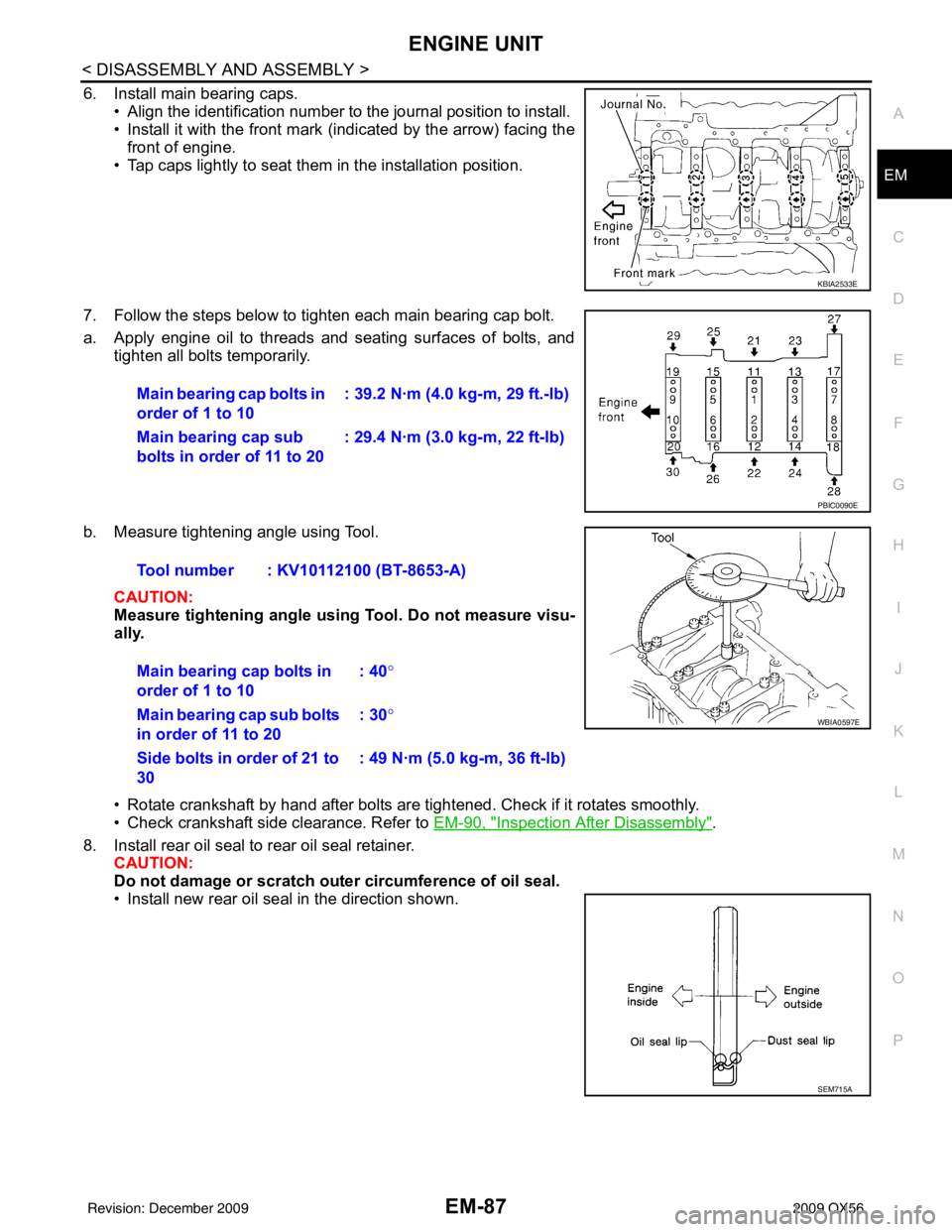
6. Install main bearing caps.
• Align the identification number to the journal position to install.
• Install it with the front mark (indicated by the arrow) facing thefront of engine.
• Tap caps lightly to seat them in the installation position.
7. Follow the steps below to tighten each main bearing cap bolt.
a. Apply engine oil to threads and seating surfaces of bolts, and tighten all bolts temporarily.
b. Measure tightening angle using Tool. CAUTION:
Measure tightening angle usin g Tool. Do not measure visu-
ally.
• Rotate crankshaft by hand after bolts are tightened. Check if it rotates smoothly.
• Check crankshaft side clearance. Refer to EM-90, "
Inspection After Disassembly".
8. Install rear oil seal to rear oil seal retainer. CAUTION:
Do not damage or scratch ou ter circumference of oil seal.
• Install new rear oil seal in the direction shown.
KBIA2533E
Main bearing cap bolts in
order of 1 to 10 : 39.2 N·m (4.0 kg-m, 29 ft.-lb)
Main bearing cap sub
bolts in order of 11 to 20 : 29.4 N·m (3.0 kg-m, 22 ft-lb)
PBIC0090E
Tool number : KV10112100 (BT-8653-A)
Main bearing cap bolts in
order of 1 to 10 : 40
°
Main bearing cap sub bolts
in order of 11 to 20 : 30
°
Side bolts in order of 21 to
30 : 49 N·m (5.0 kg-m, 36 ft-lb)
WBIA0597E
SEM715A
Revision: December 20092009 QX56
Page 1912 of 4171
ENGINE UNITEM-89
< DISASSEMBLY AND ASSEMBLY >
C
DE
F
G H
I
J
K L
M A
EM
NP
O
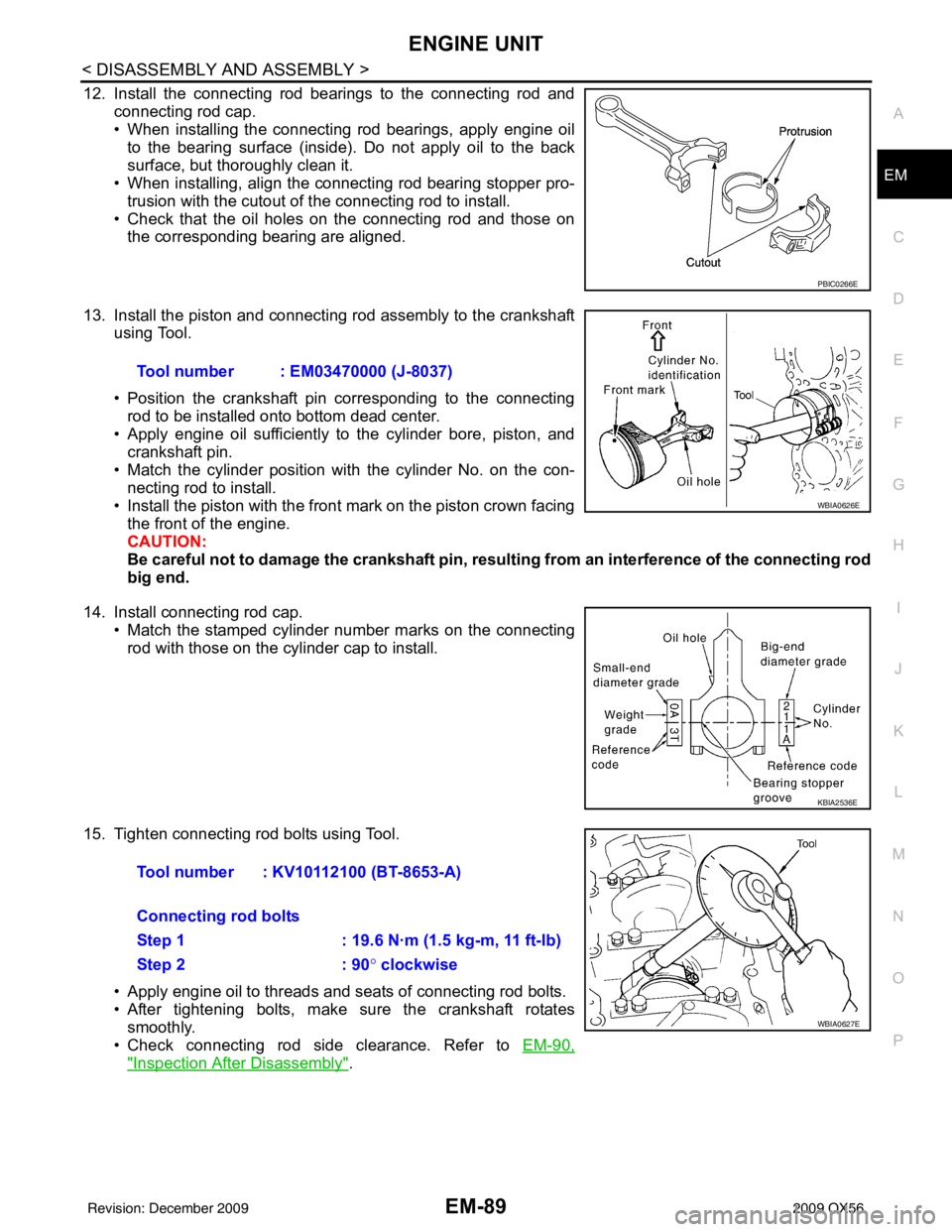
12. Install the connecting rod bearings to the connecting rod and
connecting rod cap.
• When installing the connecting rod bearings, apply engine oilto the bearing surface (inside). Do not apply oil to the back
surface, but thoroughly clean it.
• When installing, align the connecting rod bearing stopper pro-
trusion with the cutout of the connecting rod to install.
• Check that the oil holes on the connecting rod and those on the corresponding bearing are aligned.
13. Install the piston and connecting rod assembly to the crankshaft using Tool.
• Position the crankshaft pin corresponding to the connecting
rod to be installed onto bottom dead center.
• Apply engine oil sufficiently to the cylinder bore, piston, and
crankshaft pin.
• Match the cylinder position with the cylinder No. on the con- necting rod to install.
• Install the piston with the front mark on the piston crown facing the front of the engine.
CAUTION:
Be careful not to damage the crankshaft pin, resu lting from an interference of the connecting rod
big end.
14. Install connecting rod cap. • Match the stamped cylinder number marks on the connectingrod with those on the cylinder cap to install.
15. Tighten connecting rod bolts using Tool. • Apply engine oil to threads and seats of connecting rod bolts.
• After tightening bolts, make sure the crankshaft rotatessmoothly.
• Check connecting rod side clearance. Refer to EM-90,
"Inspection After Disassembly".
PBIC0266E
Tool number : EM03470000 (J-8037)
WBIA0626E
KBIA2536E
Tool number : KV10112100 (BT-8653-A)
Connecting rod bolts
Step 1 : 19.6 N·m (1.5 kg-m, 11 ft-lb)
Step 2: 90° clockwise
WBIA0627E
Revision: December 20092009 QX56
Page 1915 of 4171
EM-92
< DISASSEMBLY AND ASSEMBLY >
ENGINE UNIT
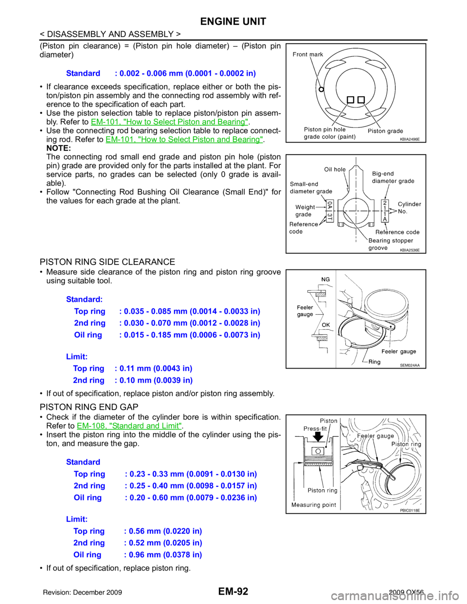
(Piston pin clearance) = (Piston pin hole diameter) – (Piston pin
diameter)
• If clearance exceeds specification, replace either or both the pis-
ton/piston pin assembly and the connecting rod assembly with ref-
erence to the specification of each part.
• Use the piston selection table to replace piston/piston pin assem-
bly. Refer to EM-101, "
How to Select Piston and Bearing".
• Use the connecting rod bearing selection table to replace connect- ing rod. Refer to EM-101, "
How to Select Piston and Bearing".
NOTE:
The connecting rod small end grade and piston pin hole (piston
pin) grade are provided only for the parts installed at the plant. For
service parts, no grades can be selected (only 0 grade is avail-
able).
• Follow "Connecting Rod Bushing Oil Clearance (Small End)" for the values for each grade at the plant.
PISTON RING SIDE CLEARANCE
• Measure side clearance of the piston ring and piston ring grooveusing suitable tool.
• If out of specification, replac e piston and/or piston ring assembly.
PISTON RING END GAP
• Check if the diameter of the cyli nder bore is within specification.
Refer to EM-108, "
Standard and Limit".
• Insert the piston ring into the middle of the cylinder using the pis- ton, and measure the gap.
• If out of specification, replace piston ring. Standard : 0.002 - 0.006 mm (0.0001 - 0.0002 in)
KBIA2496E
KBIA2536E
Standard:
Top ring : 0.035 - 0.085 mm (0.0014 - 0.0033 in)
2nd ring : 0.030 - 0.070 mm (0.0012 - 0.0028 in)
Oil ring : 0.015 - 0.185 mm (0.0006 - 0.0073 in)
Limit: Top ring : 0.11 mm (0.0043 in)
2nd ring : 0.10 mm (0.0039 in)
SEM024AA
Standard Top ring : 0.23 - 0.33 mm (0.0091 - 0.0130 in)
2nd ring : 0.25 - 0.40 mm (0.0098 - 0.0157 in)
Oil ring : 0.20 - 0.60 mm (0.0079 - 0.0236 in)
Limit: Top ring : 0.56 mm (0.0220 in)
2nd ring : 0.52 mm (0.0205 in)
Oil ring : 0.96 mm (0.0378 in)
PBIC0118E
Revision: December 20092009 QX56
Page 1916 of 4171
ENGINE UNITEM-93
< DISASSEMBLY AND ASSEMBLY >
C
DE
F
G H
I
J
K L
M A
EM
NP
O
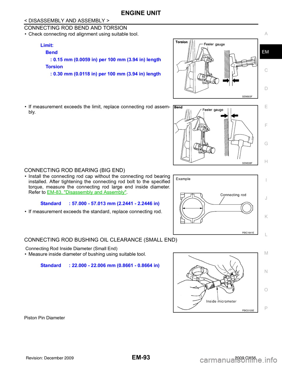
CONNECTING ROD BEND AND TORSION
• Check connecting rod alignment using suitable tool.
• If measurement exceeds the limi
t, replace connecting rod assem-
bly.
CONNECTING ROD BEARING (BIG END)
• Install the connecting rod cap without the connecting rod bearing installed. After tightening the connecting rod bolt to the specified
torque, measure the connecting rod large end inside diameter.
Refer to EM-83, "
Disassembly and Assembly".
• If measurement exceeds the standard, replace connecting rod.
CONNECTING ROD BUSHING OIL CLEARANCE (SMALL END)
Connecting Rod Inside Diameter (Small End)
• Measure inside diameter of bushing using suitable tool.
Piston Pin Diameter
Limit: Bend: 0.15 mm (0.0059 in) per 100 mm (3.94 in) length
To r s i o n : 0.30 mm (0.0118 in) per 100 mm (3.94 in) length
SEM003F
SEM038F
Standard : 57.000 - 57.013 mm (2.2441 - 2.2446 in)
PBIC1641E
Standard : 22.000 - 22.006 mm (0.8661 - 0.8664 in)
PBIC0120E
Revision: December 20092009 QX56
Page 1922 of 4171
ENGINE UNITEM-99
< DISASSEMBLY AND ASSEMBLY >
C
DE
F
G H
I
J
K L
M A
EM
NP
O
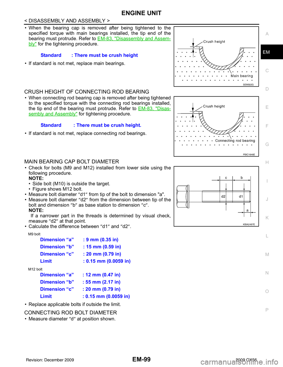
• When the bearing cap is removed after being tightened to the
specified torque with main bearings installed, the tip end of the
bearing must protrude. Refer to EM-83, "
Disassembly and Assem-
bly" for the tightening procedure.
• If standard is not met, replace main bearings.
CRUSH HEIGHT OF CONNECTING ROD BEARING
• When connecting rod bearing cap is removed after being tightened to the specified torque with the connecting rod bearings installed,
the tip end of the bearing must protrude. Refer to EM-83, "
Disas-
sembly and Assembly" for tightening procedure.
• If standard is not met, replace connecting rod bearings.
MAIN BEARING CAP BOLT DIAMETER
• Check for bolts (M9 and M12) installed from lower side using the following procedure.
NOTE:
• Side bolt (M10) is outside the target.
• Figure shows M12 bolt.
• Measure bolt diameter ″ d1″ from tip of the bolt to dimension "a".
• Measure bolt diameter ″d2″ from the dimension between tip of the
bolt and dimension ″b ″ as base station to dimension ″c″ .
NOTE:
If a narrower part in the threads is determined by visual check,
measure ″d2″ at that point.
• Calculate the difference between ″d1″ and ″d2″ .
M9 bolt
M12 bolt
• Replace applicable bolts if outside the limit.
CONNECTING ROD BOLT DIAMETER
• Measure diameter ″d ″ at position shown.
Standard : There must be crush height
SEM502G
Standard : There must be crush height.
PBIC1646E
KBIA2497E
Dimension “a” : 9 mm (0.35 in)
Dimension “b” : 15 mm (0.59 in)
Dimension “c” : 20 mm (0.79 in)
Limit : 0.15 mm (0.0059 in)
Dimension “a” : 12 mm (0.47 in)
Dimension “b” : 55 mm (2.17 in)
Dimension “c” : 20 mm (0.79 in)
Limit : 0.15 mm (0.0059 in)
Revision: December 20092009 QX56
Page 1942 of 4171
EX-1
ENGINE
C
DE
F
G H
I
J
K L
M
SECTION EX
A
EX
N
O P
CONTENTS
EXHAUST SYSTEM
PRECAUTION ....... ........................................2
PRECAUTIONS .............................................. .....2
Precaution for Supplemental Restraint System
(SRS) "AIR BAG" and "SEAT BELT PRE-TEN-
SIONER" ............................................................. ......
2
Precaution Necessary for Steering Wheel Rota-
tion After Battery Disconnect ............................... ......
2
PREPARATION ............................................4
PREPARATION .............................................. .....4
Special Service Tool ........................................... ......4
Commercial Service Tool .................................... .....4
ON-VEHICLE MAINTENANCE .....................5
EXHAUST SYSTEM ...........................................5
Checking Exhaust System ................................... .....5
ON-VEHICLE REPAIR ..................................6
EXHAUST SYSTEM ...........................................6
Exploded View ..................................................... .....6
Removal and Installation ..........................................6
Revision: December 20092009 QX56
Page 1948 of 4171
EXHAUST SYSTEMEX-7
< ON-VEHICLE REPAIR >
C
DE
F
G H
I
J
K L
M A
EX
NP
O
• Before installing a new heated o
xygen sensor, clean and lube the exhaust tube threads using suit-
able tool.
• Discard any heated oxygen sensor which has been dr opped from a height of more than 0.5 m (19.7
in) onto a hard surface such as a co ncrete floor; replace with a new one.
• Do not over-tighten the heated oxygen sensor. Doing so may damage the heated oxygen sensor, resulting in the MIL coming on.
• If any mounting insulator is badly deformed, repair or replace it. If deposits such as mud pile up on
the mounting insulators, clean and inspect them.
• Temporarily tighten the nuts on the exhaust manifold side and th e bolts on the vehicle side. Check
each part for interference with other components, an d then tighten the nuts and bolts to specifica-
tion.
INSPECTION AFTER INSTALLATION
• With the engine running, check exhaust tube joints for gas leakage and unusual noises.
• Check to ensure that mounting brackets and mount ing rubbers are installed properly and free from undue
stress. Improper installation could resu lt in excessive noise and vibration.
Oxygen sensor thread cleaner A: (J-43897-18)
Oxygen sensor thread cleaner B: (J-43897-12)
Revision: December 20092009 QX56