2009 INFINITI QX56 check engine
[x] Cancel search: check enginePage 2228 of 4171
GI-34
< BASIC INSPECTION >
SERVICE INFORMATION FOR ELECTRICAL INCIDENT
BASIC INSPECTION
SERVICE INFORMATION FOR ELECTRICAL INCIDENT
Work FlowINFOID:0000000003771212
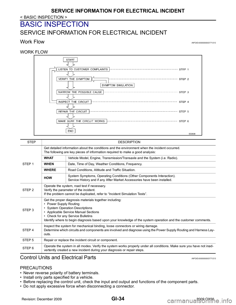
WORK FLOW
Control Units and Electrical PartsINFOID:0000000003771213
PRECAUTIONS
• Never reverse polarity of battery terminals.
• Install only parts specified for a vehicle.
• Before replacing the control unit, check the i nput and output and functions of the component parts.
• Do not apply excessive force when disconnecting a connector.
SGI838
STEP DESCRIPTION
STEP 1 Get detailed information about the conditions and the environment when the incident occurred.
The following are key pieces of information required to make a good analysis:
WHAT
Vehicle Model, Engine, Transmission/Transaxle and the System (i.e. Radio).
WHEN Date, Time of Day, Weather Conditions, Frequency.
WHERE Road Conditions, Altitude and Traffic Situation.
HOW System Symptoms, Operating Conditions
(Other Components Interaction).
Service History and if any After Market Accessories have been installed.
STEP 2 Operate the system, road test if necessary.
Verify the parameter of the incident.
If the problem cannot be duplicated, refer to “Incident Simulation Tests”.
STEP 3 Get the proper diagnosis materials together including:
• Power Supply Routing
• System Operation Descriptions
• Applicable Service Manual Sections
• Check for any Service Bulletins
Identify where to begin diagnosis based upon your knowledge of the system operation and the customer comments.
STEP 4 Inspect the system for mechanical binding, loose connectors or wiring damage.
Determine which circuits and components are involved and diagnose using the Power Supply Routing and Harness Lay-
outs.
STEP 5 Repair or replace the incident circuit or component.
STEP 6 Operate the system in all modes. Verify the system works properly under all conditions. Make sure you have not inad-
vertently created a new incident during your diagnosis or repair steps.
Revision: December 20092009 QX56
Page 2233 of 4171
SERVICE INFORMATION FOR ELECTRICAL INCIDENTGI-39
< BASIC INSPECTION >
C
DE
F
G H
I
J
K L
M B
GI
N
O P
lowing section illustrates ways to simulate the c onditions/environment under which the owner experiences an
electrical incident.
The section is broken into the six following topics:• Vehicle vibration
• Heat sensitive
• Freezing
• Water intrusion
• Electrical load
• Cold or hot start up
Get a thorough description of the incident from the customer . It is important for simulating the conditions of the
problem.
VEHICLE VIBRATION
The problem may occur or become worse while driving on a rough road or when engine is vibrating (idle with
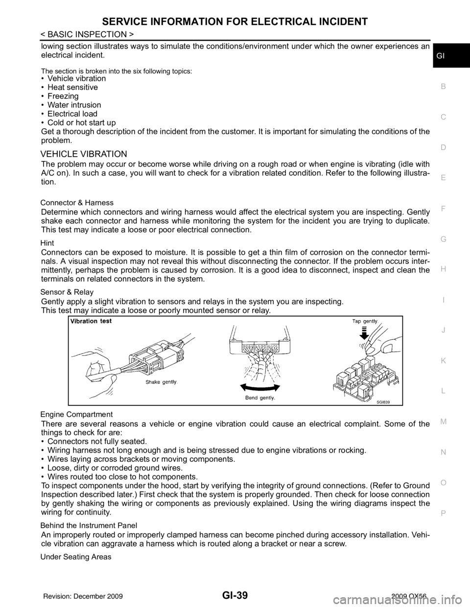
A/C on). In such a case, you will want to check for a vibration related condition. Refer to the following illustra-
tion.
Connector & Harness
Determine which connectors and wiring harness would affect the electrical system you are inspecting. Gently
shake each connector and harness while monitoring the syst em for the incident you are trying to duplicate.
This test may indicate a loose or poor electrical connection.
Hint
Connectors can be exposed to moisture. It is possible to get a thin film of corrosion on the connector termi-
nals. A visual inspection may not reveal this without disconnecting the connector. If the problem occurs inter-
mittently, perhaps the problem is caused by corrosi on. It is a good idea to disconnect, inspect and clean the
terminals on related connectors in the system.
Sensor & Relay
Gently apply a slight vibration to sensors and relays in the system you are inspecting.
This test may indicate a loose or poorly mounted sensor or relay.
Engine Compartment
There are several reasons a vehicle or engine vibration could cause an electrical complaint. Some of the
things to check for are:
• Connectors not fully seated.
• Wiring harness not long enough and is being stressed due to engine vibrations or rocking.
• Wires laying across brackets or moving components.
• Loose, dirty or corroded ground wires.
• Wires routed too close to hot components.
To inspect components under the hood, start by verifyi ng the integrity of ground connections. (Refer to Ground
Inspection described later.) First check that the system is properly grounded. Then check for loose connection
by gently shaking the wiring or components as previous ly explained. Using the wiring diagrams inspect the
wiring for continuity.
Behind the Instrument Panel
An improperly routed or improperly clamped harness can become pinched during accessory installation. Vehi-
cle vibration can aggravate a harness which is routed along a bracket or near a screw.
Under Seating Areas
SGI839
Revision: December 20092009 QX56
Page 2240 of 4171
GI-46
< BASIC INSPECTION >
CONSULT-III CHECKING SYSTEM
CONSULT-III CHECKING SYSTEM
DescriptionINFOID:0000000003771217
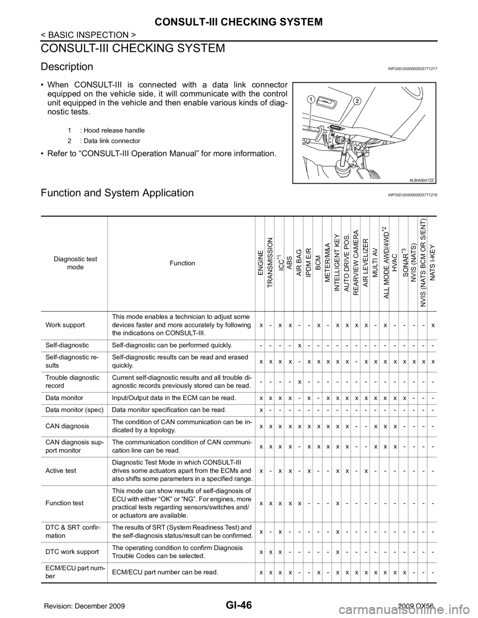
• When CONSULT-III is connected with a data link connectorequipped on the vehicle side, it will communicate with the control
unit equipped in the vehicle and then enable various kinds of diag-
nostic tests.
• Refer to “CONSULT-III Operation Manual” for more information.
Function and System ApplicationINFOID:0000000003771218
1 : Hood release handle
2 : Data link connector
ALBIA0047ZZ
Diagnostic test mode Function
ENGINE
TRANSMISSION
ICC
*1
ABS
AIR BAG
IPDM E/R BCM
METER/M&A
INTELLIGENT KEY
AUTO DRIVE POS.
REARVIEW CAMERA AIR LEVELIZER MULTI AV
ALL MODE AWD/4WD
*2
HVAC
SONAR
*3
NVIS (NATS)
NVIS (NATS BCM OR S/ENT) NATS I-KEY
Work support This mode enables a technician to adjust some
devices faster and more accurately by following
the indications on CONSULT-III. x-xx--x-xxxx-x----x
Self-diagnostic Self-diagnostic can be performed quickly. ----x--------------
Self-diagnostic re-
sults Self-diagnostic results can be read and erased
quickly.
xxx x- xxxxx- xxx xxxxx
Trouble diagnostic
record Current self-diagnostic results and all trouble di-
agnostic records previously stored can be read.
--- - x--- - ----------
Data monitor Input/Output data in the ECM can be read. xxx x- x- xxxxxxx xx- - -
Data monitor (spec) Data monitor specification can be read. x------------------
CAN diagnosis The condition of CAN communication can be in-
dicated by a topology.
xxx xxxxxxx- - xx x- - - -
CAN diagnosis sup-
port monitor The communication condition of CAN communi-
cation line can be read.
xxx x- xxxxx- - xx x- - - -
Active test Diagnostic Test Mode
in which CONSULT-III
drives some actuators apart from the ECMs and
also shifts some parameters in a specified range. x-xx-x--xx-x-------
Function test This mode can show results of self-diagnosis of
ECU with either “OK” or “NG”. For engines, more
practical tests regarding sensors/switches and/
or actuators are available. xxxxx---x----------
DTC & SRT confir-
mation The results of SRT (System Readiness Test) and
the self-diagnosis status/result can be confirmed.
x-x-----x----------
DTC work support The operating condition to confirm Diagnosis
Trouble Codes can be selected. xxx-----x----------
ECM/ECU part num-
ber ECM/ECU part number can be read.
xxx x- - x- xxxxxx xx- - -
Revision: December 20092009 QX56
Page 2241 of 4171

CONSULT-III CHECKING SYSTEMGI-47
< BASIC INSPECTION >
C
DE
F
G H
I
J
K L
M B
GI
N
O P
x : Applicable
*1: With intelligent cruise control
*2: With 4-wheel drive
*3: With front and rear sonar system
CONSULT-III Data Link Connector (DLC) CircuitINFOID:0000000003771219
INSPECTION PROCEDURE
If the CONSULT-III cannot diagnose the sys tem properly, check the following items.
NOTE:
The CAN and DDL2 circuits from DLC pins 6, 7 and 14 may be connected to more than one system. A short in
any circuit connected to a control unit in one system may affect CONSULT-III access to other systems.
ECU discriminated
No.Classification number of a replacement ECU can
be read to prevent an incorrect ECU from being
installed.
----x--------------
Passenger Airbag Displays the STATUS (readiness) of the front
passenger air bag.
----x--------------
AV COMM monitor The condition of AV communication can be indi-
cated. ------------x------
Configuration Sets control module para
meters to match vehicle
options. ------x------------
Steering lock re-
lease The condition of steering lock release solenoid. -----------------x-
PIN read This mode shows the BCM-specific 5-digit code.-----------------x-
Control unit
initialization All registered ignition key IDs in NATS compo-
nents can be initialized and new IDs can be reg-
istered.
----------------x--
Diagnostic test
mode Function
ENGINE
TRANSMISSION
ICC
*1
ABS
AIR BAG
IPDM E/R BCM
METER/M&A
INTELLIGENT KEY
AUTO DRIVE POS.
REARVIEW CAMERA AIR LEVELIZER
MULTI AV
ALL MODE AWD/4WD
*2
HVAC
SONAR
*3
NVIS (NATS)
NVIS (NATS BCM OR S/ENT) NATS I-KEY
Symptom Check item
CONSULT-III cannot access
any system. • CONSULT-III DLC power supply circuit (Terminal 8) and ground circuit (Terminal 4)
CONSULT-III cannot access in-
dividual system. (Other sys-
tems can be accessed.) • Power supply and ground circuit for the control unit of the system (For detailed circuit, refer to wiring
diagram for each system.)
• Open or short circuit between the system and CONSULT-III DLC (For detailed circuit, refer to wiring diagram for each system.)
• Open or short circuit CAN communication line. Refer to LAN-14, "
Trouble Diagnosis Flow Chart".
Revision: December 20092009 QX56
Page 2245 of 4171
SQUEAK AND RATTLE TROUBLE DIAGNOSISGW-3
< SYMPTOM DIAGNOSIS >
C
DE
F
G H
I
J
L
M A
B
GW
N
O P
If possible, drive the vehicle with the customer until the noise is duplicated. Note any additional information on
the Diagnostic Worksheet regarding the conditions or lo cation of the noise. This information can be used to
duplicate the same conditions when you confirm the repair.
If the noise can be duplicated easily during the test drive, to help identify the source of the noise, try to dupli-
cate the noise with the vehicle stopped by doing one or all of the following:
1) Close a door.
2) Tap or push/pull around the area where the noise appears to be coming from.
3) Rev the engine.
4) Use a floor jack to recreate vehicle “twist”.
5) At idle, apply engine load (electrical load, half- clutch on M/T model, drive position on A/T model).
6) Raise the vehicle on a hoist and hit a tire with a rubber hammer.
• Drive the vehicle and attempt to duplicate the conditions the customer states exist when the noise occurs.
• If it is difficult to duplicate the noise, drive the vehicle slowly on an undulating or rough road to stress the vehicle body.
CHECK RELATED SERVICE BULLETINS
After verifying the customer concern or symptom, check ASIST for Technical Service Bulletins (TSBs) related
to that concern or symptom.
If a TSB relates to the symptom, follow the procedure to repair the noise.
LOCATE THE NOISE AND IDENTIFY THE ROOT CAUSE
1. Narrow down the noise to a general area.To help pinpoint the source of the noise, use a listening tool (Chassis Ear: J-39570, Engine Ear: J-39565 and mechanic's stethoscope).
2. Narrow down the noise to a more specific area and identify the cause of the noise by:
• removing the components in the area that you suspect the noise is coming from. Do not use too much force when removing clips and fasteners, otherwise clips and fasteners can be broken
or lost during the repair, resulting in the creation of new noise.
• tapping or pushing/pulling the component that you suspect is causing the noise.
Do not tap or push/pull the component with excessive force, otherwise the noise will be eliminated only tem-
porarily.
• feeling for a vibration with your hand by touching the component(s) that you suspect is (are) causing the
noise.
• placing a piece of paper between components that you suspect are causing the noise.
• looking for loose components and contact marks. Refer to GW-4, "
Generic Squeak and Rattle Troubleshooting".
REPAIR THE CAUSE
• If the cause is a loose component, tighten the component securely.
• If the cause is insufficient clearance between components:
- separate components by repositioning or loos ening and retightening the component, if possible.
- insulate components with a suitable insulator such as urethane pads, foam blocks, felt cloth tape or urethane tape. A NISSAN Squeak and Rattle Kit (J-43980) is available through your authorized NISSAN Parts Depart-
ment.
CAUTION:
Do not use excessive force as many components are constructed of plastic and may be damaged.
Always check with the Parts Department for the latest parts information.
The following materials are contained in the NISSAN Squeak and Rattle Kit (J-43980). Each item can be
ordered separately as needed.
URETHANE PADS [1.5 mm (0.059 in) thick]
Insulates connectors, harness, etc.
76268-9E005: 100 ×135 mm (3.94 ×5.31 in)/76884-71L01: 60 ×85 mm (2.36× 3.35 in)/76884-71L02: 15× 25
mm (0.59 ×0.98 in)
INSULATOR (Foam blocks)
Insulates components from contact. Can be used to fill space behind a panel.
73982-9E000: 45 mm (1.77 in) thick, 50× 50 mm (1.97×1.97 in)/73982-50Y00: 10 mm (0.39 in) thick,
50× 50 mm (1.97 ×1.97 in)
INSULATOR (Light foam block)
80845-71L00: 30 mm (1.18 in) thick, 30 ×50 mm (1.18 ×1.97 in)
FELT CLOTH TAPE
Used to insulate where movement does not occu r. Ideal for instrument panel applications.
Revision: December 20092009 QX56
Page 2274 of 4171
HA-10
< PRECAUTION >
PRECAUTIONS
Precaution for Service of Compressor
INFOID:0000000003775293
Plug all openings to prevent moisture and foreign matter from entering.
When the compressor is removed, store it in th e same position as it is when mounted on the car.
When replacing or repairing compressor, follow “Maintenance of Oil Quantity in Compressor”
exactly. Refer to HA-22, "Maintenance of Oil Quantity in Compressor"
.
Keep friction surfaces between clut ch and pulley clean. If the surface is contaminated with oil, wipe
it off by using a clean waste cloth moistened with thinner.
After compressor service operation, turn the compressor shaft by hand more than 5 turns in both
directions. This will equally dist ribute oil inside the compressor. After the compressor is installed,
let the engine idle and oper ate the compressor for 1 hour.
After replacing the compressor magnet clutch, ap ply voltage to the new one and check for normal
operation. Refer to HA-32, "Removal and Installa tion for Compressor Clutch"
.
Precaution for Service EquipmentINFOID:0000000003775294
RECOVERY/RECYCLING EQUIPMENT
Follow the manufacturer's instructions for machi ne operation and machine maintenance. Never introduce any
refrigerant other than that specified into the machine.
ELECTRONIC LEAK DETECTOR
Follow the manufacturer's instructions for tester operation and tester maintenance.
VACUUM PUMP
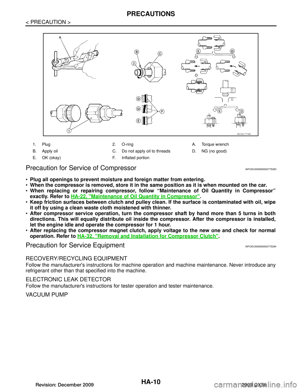
1. Plug 2. O-ring A. Torque wrench
B. Apply oil C. Do not apply oil to threads D. NG (no good)
E. OK (okay) F. Inflated portion
WJIA1774E
Revision: December 20092009 QX56
Page 2286 of 4171
HA-22
< ON-VEHICLE MAINTENANCE >
OIL
OIL
Maintenance of Oil Quantity in CompressorINFOID:0000000003775302
The oil in the compressor circulates through the system with the refrigerant. Add oil to compressor when
replacing any component or after a large refrigerant leakage has occurred. It is important to maintain the spec-
ified amount.
If oil quantity is not maintained properly, the following malfunctions may result:
Lack of oil: May lead to a seized compressor
Excessive oil: Inadequate cooling (thermal exchange interference)
OIL
Name: NISSAN A/C System Oil Type S or equivalent
CHECKING AND ADJUSTING
CAUTION:
If excessive oil leakage is noted, do no t perform the oil return operation.
Start the engine and set the following conditions:
Test Condition
Engine speed: Idling to 1,200 rpm
A/C switch: On
Blower fan speed: MAX position
Temp. control: Optional [Set so that intake air temperature is 25 ° to 30 ° C (77 ° to 86 °F)]
Intake position: Recirculation ( )
Perform oil return operation for about ten minutes
Adjust the oil quantity according to the following table.
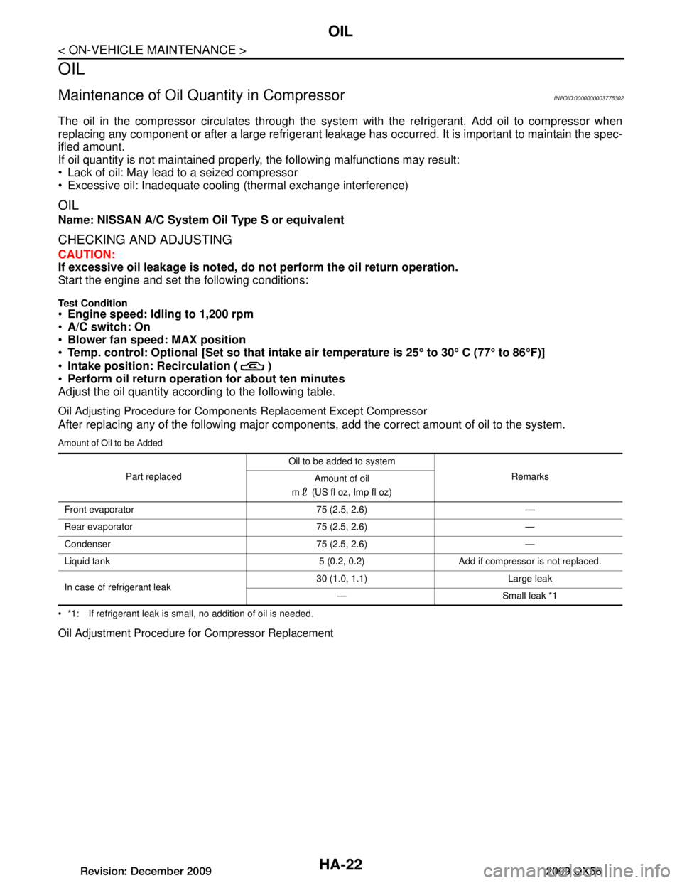
Oil Adjusting Procedure for Components Replacement Except Compressor
After replacing any of the following major component s, add the correct amount of oil to the system.
Amount of Oil to be Added
*1: If refrigerant leak is small, no addition of oil is needed.
Oil Adjustment Procedure for Compressor Replacement
Part replacedOil to be added to system
Remarks
Amount of oil
m (US fl oz, Imp fl oz)
Front evaporator 75 (2.5, 2.6) —
Rear evaporator 75 (2.5, 2.6) —
Condenser 75 (2.5, 2.6) —
Liquid tank 5 (0.2, 0.2) Add if compressor is not replaced.
In case of refrigerant leak 30 (1.0, 1.1) Large leak
— Small leak *1
Revision: December 20092009 QX56
Page 2288 of 4171

HA-24
< ON-VEHICLE MAINTENANCE >
FLUORESCENT LEAK DETECTOR
FLUORESCENT LEAK DETECTOR
Checking of Refrigerant LeaksINFOID:0000000003775303
PRELIMINARY CHECK
Perform a visual inspection of all refrigeration parts, fittings, hoses and components for signs of A/C oil leak-
age, damage, and corrosion. Any A/C oil leakage may indicate an area of refrigerant leakage. Allow extra
inspection time in these areas when using either an el ectronic refrigerant leak detector (J-41995) or fluores-
cent dye leak detector (J-42220).
If any dye is observed using a fluor escent dye leak detector (J-42220), c onfirm the leak using a electronic
refrigerant leak detector (J-41995). It is possible that the dye is from a prior leak that was repaired and not
properly cleaned.
When searching for leaks, do not stop when one leak is found but continue to check for additional leaks at all
system components and connections.
When searching for refrigerant leaks using an electroni c refrigerant leak detector (J-41995), move the probe
along the suspected leak area at 25 - 50 mm (1 - 2 in) per second and no further than 6 mm (1/4 in) from the
component.
CAUTION:
Moving the electronic refrigerant l eak detector probe slower and clo ser to the suspected leak area will
improve the chances of finding a leak.
Checking System for L eaks Using the Fluorescent Dye Leak DetectorINFOID:0000000003775304
1. Check the A/C system for leaks using the fluorescent dye leak detector and safety goggles (J-42220) in a
low sunlight area (area without windows preferable). Il luminate all components, fittings and lines. The dye
will appear as a bright green/yellow area at the point of leakage. Fluorescent dye observed at the evapo-
rator drain opening indicates an evaporator core asse mbly leak (tubes, core or expansion valve).
2. If the suspected area is difficult to see, use an adjustable mirror or wipe the area with a clean shop rag or
cloth, then inspect the shop rag or cloth with the fl uorescent dye leak detector (J-42220) for dye residue.
3. After the leak is repaired, remove any residual dye using refrigerant dye cleaner (J-43872) to prevent
future misdiagnosis.
4. Perform a system performance check and then verify t he leak repair using a electronic refrigerant leak
detector (J-41995).
NOTE:
Other gases in the work area or substances on the A/C components, for example, anti-freeze, wind-
shield washer fluid, solvents and oils, may falsely tri gger the leak detector. Make sure the surfaces to be
checked are clean.
Clean with a dry cloth or blow off with shop air.
Do not allow the sensor tip of the electronic refri gerant leak detector (J-41995) to contact with any sub-
stance. This can also cause false readings and may damage the detector.
Dye InjectionINFOID:0000000003775305
NOTE:
This procedure is only necessary when recharging t he system or when the compressor has seized and must
be replaced.
1. Check the A/C system static (at rest) pressure . Pressure must be at least 345 kPa (3.52 kg/cm
2 , 50 psi).
2. Pour one bottle 7.4 cc (1/4 ounce) of the HFC-134a (R -134a) fluorescent leak detection dye (J-41447) into
the HFC-134a (R-134a) dye injector (J-41459).
CAUTION:
If repairing the A/C system or replacing a co mponent, pour the HFC-134a (R-134a) fluorescent leak
detection dye (J-41447) directly into the open system connection and proceed with the service
procedures.
3. Connect the refrigerant dye injector (J- 41459) to the low-pressure service valve.
4. Start the engine and switch the A/C system ON.
5. When the A/C system is operating (compressor runni ng), inject one bottle 7.4 cc (1/4 ounce) of HFC-134a
(R-134a) fluorescent leak detection dye (J-41447) th rough the low-pressure service valve using HFC-
134a (R-134a) dye injector (J-41459). Refer to the manufacturer's operating instructions.
Revision: December 20092009 QX56