2009 INFINITI QX56 check engine
[x] Cancel search: check enginePage 2178 of 4171
FSU-8
< ON-VEHICLE MAINTENANCE >
ON-VEHICLE SERVICE
• Always perform the following procedure on a flat surface.
• Make sure that no person is in front of the vehicle before pushing it.
1. Bounce the front of vehicle up and down to stabilize the vehicle height (posture).
2. Push the vehicle straight ahead about 5 m (16 ft).
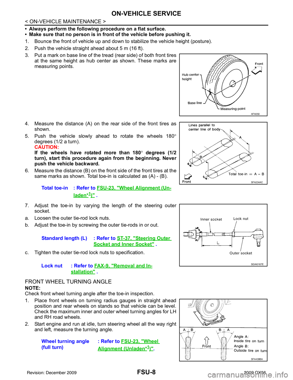
3. Put a mark on base line of the tread (rear side) of both front tires at the same height as hub center as shown. These marks are
measuring points.
4. Measure the distance (A) on the rear side of the front tires as shown.
5. Push the vehicle slowly ahead to rotate the wheels 180 °
degrees (1/2 a turn).
CAUTION:
If the wheels have rotated more than 180 ° degrees (1/2
turn), start this procedure again from the beginning. Never
push the vehicle backward.
6. Measure the distance (B) on the front side of the front tires at the
same marks as shown. Total toe- in is calculated as (A) - (B).
7. Adjust the toe-in by varying the length of the steering outer socket.
a. Loosen the outer tie-rod lock nuts.
b. Adjust the toe-in by screwing the outer tie-rods in or out.
c. Tighten the outer tie-rod lock nuts to specification.
FRONT WHEEL TURNING ANGLE
NOTE:
Check front wheel turning angle after the toe-in inspection.
1. Place front wheels on turning radius gauges in straight ahead position and rear wheels on stands so that vehicle can be level.
Check the maximum inner and outer wheel turning angles for LH
and RH road wheels.
2. Start engine and run at idle, turn steering wheel all the way right and left, measure the turning angle.
AFA050
Total toe-in : Refer to FSU-23, "Wheel Alignment (Un-
laden*1)" .
SFA234AC
Standard length (L) : Refer to ST-37, "Steering Outer
Socket and Inner Socket" .
Lock nut : Refer to FA X - 9 , "
Removal and In-
stallation" .
SGIA0167E
Wheel turning angle
(full turn) : Refer to
FSU-23, "Wheel
Alignment (Unladen*1)".
SFA439BA
Revision: December 20092009 QX56
Page 2185 of 4171
STABILIZER BARFSU-15
< REMOVAL AND INSTALLATION >
C
DF
G H
I
J
K L
M A
B
FSU
N
O P
STABILIZER BAR
Removal and InstallationINFOID:0000000003772275
REMOVAL
1. Remove engine under cover using power tool.
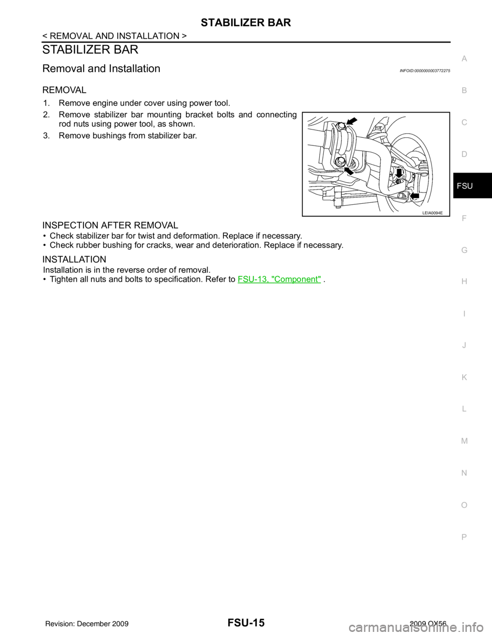
2. Remove stabilizer bar mounting bracket bolts and connecting rod nuts using power tool, as shown.
3. Remove bushings from stabilizer bar.
INSPECTION AFTER REMOVAL
• Check stabilizer bar for twist and deformation. Replace if necessary.
• Check rubber bushing for cracks, wear and deterioration. Replace if necessary.
INSTALLATION
Installation is in the reverse order of removal.
• Tighten all nuts and bolts to specification. Refer to FSU-13, "
Component" .
LEIA0094E
Revision: December 20092009 QX56
Page 2195 of 4171

GI-1
GENERAL INFORMATION
C
DE
F
G H
I
J
K L
M B
GI
SECTION GI
N
O P
CONTENTS
GENERAL INFORMATION
HOW TO USE THIS MANU AL ......................3
HOW TO USE THIS MANUAL ....................... .....3
Description .......................................................... ......3
Terms ........................................................................3
Units ..........................................................................3
Contents ....................................................................3
Relation between Illustrations and Descriptions .......4
Components ..............................................................4
HOW TO FOLLOW TROUBLE DIAGNOSES .....6
Description ................................................................6
How to Follow Test Groups in Trouble Diagnosis ......6
Key to Symbols Signifying Measurements or Pro-
cedures ............................................................... ......
7
HOW TO READ WIRING DIAGRAMS ................9
Connector symbols ............................................. ......9
Sample/wiring diagram -example- ...........................10
Description ..............................................................11
ABBREVIATIONS .......................................... ....13
Abbreviation List .................................................. ....13
TIGHTENING TORQUE OF STANDARD
BOLTS ................................................................
14
Tightening Torque Table .........................................14
RECOMMENDED CHEMICAL PRODUCTS
AND SEALANTS ............................................ ....
15
Recommended Chemical Products and Sealants ....15
TERMINOLOGY .................................................16
SAE J1930 Terminology List ............................... ....16
FEATURES OF NEW MODEL .....................20
IDENTIFICATION INFORMATION .....................20
Model Variation ................................................... ....20
Identification Number ..............................................21
Identification Plate ...................................................22
Dimensions .............................................................23
Wheels & Tires .................................................... ....23
PRECAUTION ..............................................24
PRECAUTIONS .................................................24
Description ........................................................... ....24
Precaution for Supplemental Restraint System
(SRS) "AIR BAG" and "SEAT BELT PRE-TEN-
SIONER" .................................................................
24
Precaution Necessary for Steering Wheel Rota-
tion After Battery Disconnect ...................................
24
Procedures without Cowl Top Cover .......................25
General Precautions ................................................25
Three Way Catalyst .................................................27
Precaution for Fuel (Unleaded Premium Gasoline
Recommended) .......................................................
27
Multiport Fuel Injection System or Engine Control
System .....................................................................
27
Hoses ......................................................................27
Engine Oils ..............................................................28
Air Conditioning .......................................................29
LIFTING POINT .................................................30
Pantograph Jack ......................................................30
Garage Jack and Safety Stand ................................30
2-Pole Lift ................................................................30
TOW TRUCK TOWING .....................................32
Tow Truck Towing ...................................................32
Vehicle Recovery (Freeing a stuck vehicle) ............33
BASIC INSPECTION ...................................34
SERVICE INFORMATION FOR ELECTRICAL
INCIDENT ..........................................................
34
Work Flow ............................................................ ....34
Control Units and Electrical Parts ............................34
How to Check Terminal ...........................................35
Intermittent Incident ............................................. ....38
Circuit Inspection .....................................................41
CONSULT-III CHECKING SYSTEM .................46
Revision: December 20092009 QX56
Page 2211 of 4171

TERMINOLOGYGI-17
< HOW TO USE THIS MANUAL >
C
DE
F
G H
I
J
K L
M B
GI
N
O P
Exhaust gas recirculation control-BPT
valve EGRC-BPT valve
BPT valve
Exhaust gas recirculation control-solenoid
valve EGRC-solenoid valve
EGR control solenoid valve
Exhaust gas recirculation temperature sen-
sor EGRT sensorExhaust gas temperature sensor
EGR temperature sensor
Flash electrically erasable programmable
read only memory FEEPROM
***
Flash erasable programmable read only
memory FEPROM
***
Flexible fuel sensor FFS***
Flexible fuel system FF system***
Fuel pressure regulato r*** Pressure regulator
Fuel pressure regulator control solenoid
valve ***
PRVR control solenoid valve
Fuel trim FT***
Heated Oxygen sensor HO2S Exhaust gas sensor
Idle air control system IAC system Idle speed control
Idle air control valve-air regulato rIACV-air regulator Air regulator
Idle air control valve-auxiliary air control
valve IACV-AAC valve
Auxiliary air control (AAC) valve
Idle air control valve-FICD solenoid valve IACV-FICD solenoid valve FICD solenoid valve
Idle air control valve-idle up control sole-
noid valve IACV-idle up control solenoid valve Idle up control solenoid valve
Idle speed control-FI pot ISC-FI pot FI pot
Idle speed control system ISC system***
Ignition control IC***
Ignition control module ICM***
Indirect fuel injection system IFI system ***
Intake air IA Air
Intake air temperature sensor IAT sensor Air temperature sensor
Knock *** Detonation
Knock sensor KS Detonation sensor
Malfunction indicator lamp MIL Check engine light
Manifold absolute pressure MAP ***
Manifold absolute pressure sensor MAPS ***
Manifold differential pressure MDP ***
Manifold differential pressure sensor MDPS ***
Manifold su rface temperature MST ***
Manifold surface temperature sensor MSTS ***
Manifold vacuum zone MVZ ***
Manifold vacuum zone sensor MVZS***
Mass air flow sensor MAFS Air flow meter
Mixture control solenoid valve MC solenoid valveAir-fuel ratio control solenoid valve
Multiport fuel injection System MFI system Fuel injection control
NEW TERM
NEW ACRONYM /
ABBREVIATION OLD TERM
Revision: December 20092009 QX56
Page 2215 of 4171
IDENTIFICATION INFORMATIONGI-21
< FEATURES OF NEW MODEL >
C
DE
F
G H
I
J
K L
M B
GI
N
O P
Identification NumberINFOID:0000000003771190
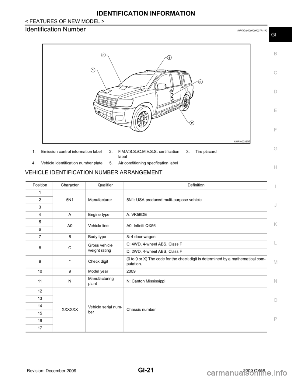
VEHICLE IDENTIFICATION NUMBER ARRANGEMENT
1. Emission control information label 2. F.M.V.S.S./C.M.V.S.S. certification label 3. Tire placard
4. Vehicle identification number plate 5. Air conditioning specfication label
AWAIA0026GB
Position Character Qualifier Definition
1 5N1 Manufacturer 5N1: USA produced multi-purpose vehicle
2
3
4 A Engine type A: VK56DE
5 A0 Vehicle line A0: Infiniti QX56
6
7 8 Body type 8: 4 door wagon
8C Gross vehicle
weight ratingC: 4WD, 4-wheel ABS, Class F
D: 2WD, 4-wheel ABS, Class F
9 * Check digit (0 to 9 or X) The code for the check digit is determined by a mathematical com-
putation.
10 9 Model year 2009
11 NManufacturing
plant
N: Canton Mississippi
12
XXXXXX Vehicle serial num-
ber Chassis number
13
14
15
16
17
Revision: December 20092009 QX56
Page 2219 of 4171
PRECAUTIONSGI-25
< PRECAUTION >
C
DE
F
G H
I
J
K L
M B
GI
N
O P
2. Use the Intelligent Key or mechanical key to turn the ignition switch to the ″ACC ″ position. At this time, the
steering lock will be released.
3. Disconnect both battery cables. The steering lock will remain released and the steering wheel can be
rotated.
4. Perform the necessary repair operation.
5. When the repair work is completed, return the ignition switch to the ″LOCK ″ position before connecting
the battery cables. (At this time, the steering lock mechanism will engage.)
6. Perform a self-diagnosis check of al l control units using CONSULT-III.
Procedures without Cowl Top CoverINFOID:0000000003771198
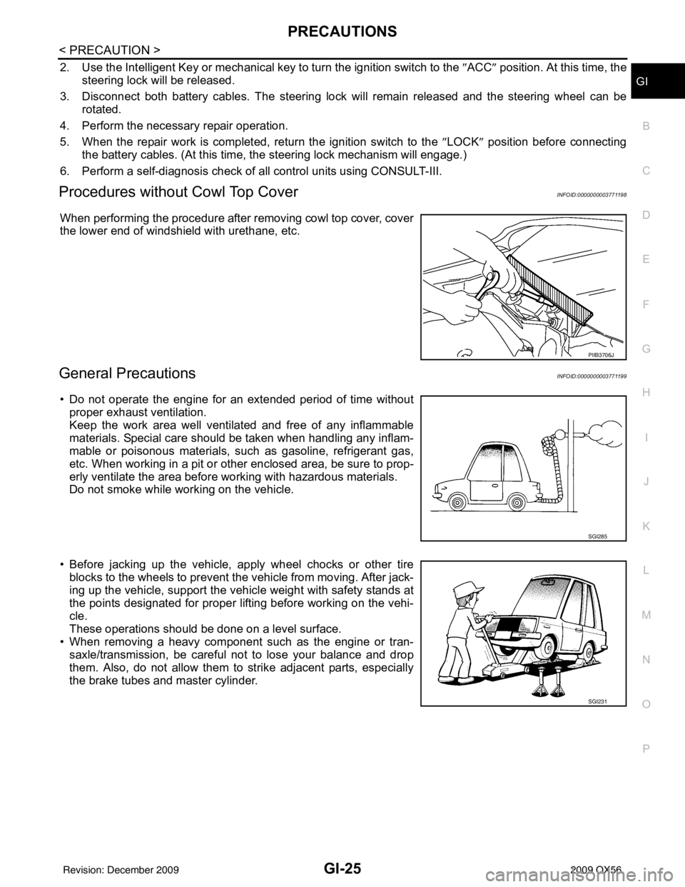
When performing the procedure after removing cowl top cover, cover
the lower end of windshield with urethane, etc.
General PrecautionsINFOID:0000000003771199
• Do not operate the engine for an extended period of time without
proper exhaust ventilation.
Keep the work area well ventilated and free of any inflammable
materials. Special care should be taken when handling any inflam-
mable or poisonous materials, such as gasoline, refrigerant gas,
etc. When working in a pit or ot her enclosed area, be sure to prop-
erly ventilate the area before working with hazardous materials.
Do not smoke while working on the vehicle.
• Before jacking up the vehicle, apply wheel chocks or other tire blocks to the wheels to prevent t he vehicle from moving. After jack-
ing up the vehicle, support the vehicle weight with safety stands at
the points designated for proper lifting before working on the vehi-
cle.
These operations should be done on a level surface.
• When removing a heavy component such as the engine or tran-
saxle/transmission, be careful not to lose your balance and drop
them. Also, do not allow them to strike adjacent parts, especially
the brake tubes and master cylinder.
PIIB3706J
SGI285
SGI231
Revision: December 20092009 QX56
Page 2220 of 4171
GI-26
< PRECAUTION >
PRECAUTIONS
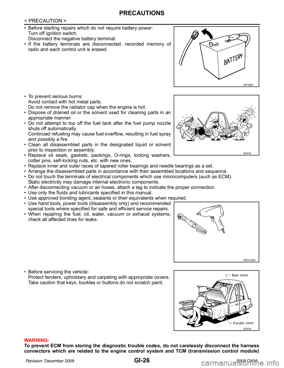
• Before starting repairs which do not require battery power:Turn off ignition switch.
Disconnect the negative battery terminal.
• If the battery terminals are disconnected, recorded memory of radio and each control unit is erased.
• To prevent serious burns: Avoid contact with hot metal parts.
Do not remove the radiator cap when the engine is hot.
• Dispose of drained oil or the solvent used for cleaning parts in an appropriate manner.
• Do not attempt to top off the fuel tank after the fuel pump nozzle
shuts off automatically.
Continued refueling may cause fuel overflow, resulting in fuel spray
and possibly a fire.
• Clean all disassembled parts in the designated liquid or solvent prior to inspection or assembly.
• Replace oil seals, gaskets, packings, O-rings, locking washers,
cotter pins, self-locking nuts, etc. with new ones.
• Replace inner and outer races of tapered roller bearings and needle bearings as a set.
• Arrange the disassembled parts in accordance with their assembled locations and sequence.
• Do not touch the terminals of electrical com ponents which use microcomputers (such as ECM).
Static electricity may damage internal electronic components.
• After disconnecting vacuum or air hoses, atta ch a tag to indicate the proper connection.
• Use only the fluids and lubricants specified in this manual.
• Use approved bonding agent, sealants or their equivalents when required.
• Use hand tools, power tools (disassembly only) and recommended special tools where specified for safe and efficient service repairs.
• When repairing the fuel, oil, water, vacuum or exhaust systems, check all affected lines for leaks.
• Before servicing the vehicle: Protect fenders, upholstery and carpeting with appropriate covers.
Take caution that keys, buckles or buttons do not scratch paint.
WARNING:
To prevent ECM from storing the diagnostic tro uble codes, do not carelessly disconnect the harness
connectors which are related to the engine control system and TCM (transmission control module)
SEF289H
SGI233
PBIC0190E
SGI234
Revision: December 20092009 QX56
Page 2221 of 4171
PRECAUTIONSGI-27
< PRECAUTION >
C
DE
F
G H
I
J
K L
M B
GI
N
O P
system. The connectors should be disconnected only when working according to the WORK FLOW of
TROUBLE DIAGNOSES in EC and TM sections.
Three Way CatalystINFOID:0000000003771200
If a large amount of unburned fuel flows into the catalyst, the catalyst temperature will be excessively high. To
prevent this, follow the instructions.
• Use unleaded gasoline only. Leaded gasoline will seriously damage the three way catalyst.
• When checking for ignition spark or measuring engine compression, make tests quickly and only when nec-
essary.
• Do not run engine when the fuel tank level is low, otherwise the engine may misfire, causing damage to the
catalyst.
Do not place the vehicle on flammable material. Keep flammable material off the exhaust pipe and the three
way catalyst.
Precaution for Fuel (Unlead ed Premium Gasoline Recommended)INFOID:0000000005892332
NISSAN/INFINITI recommends the us e of unleaded premium gasoline with an octane rating of at least 91 AKI
(Anti-Knock Index) number (Research octane number 96). If unleaded premium gasoline is not available,
unleaded regular gasoline with an octane rating of at least 87 AKI number (Research octane number 91), but
you may notice a decrease in performance.
CAUTION:
Do not use leaded gasoline. Usin g leaded gasoline will damage the three way catalyst. Using a fuel
other than that specified could adversely affect the emission cont rol devices and systems, and could
also affect the warranty coverage validity.
CAUTION:
Do not use E-85 fuel in your vehicle. Your vehicle is not designed to run on E-85 fuel. Using E-85 fuel
can cause damage to the fuel system components an d is not covered by the INFINTI vehicle limited
warranty.
Multiport Fuel Inje ction System or Engine Control SystemINFOID:0000000003771202
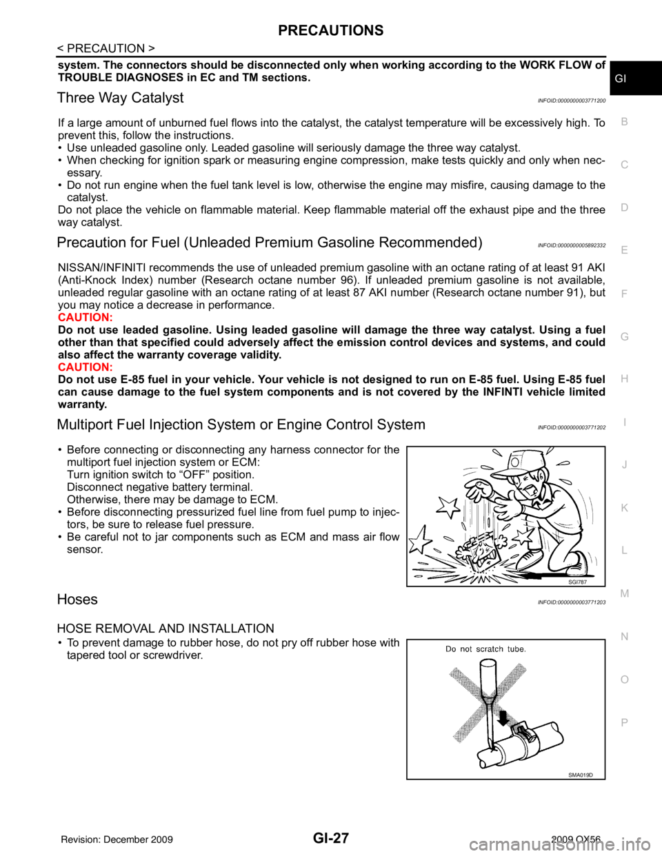
• Before connecting or disconnecting any harness connector for the
multiport fuel injection system or ECM:
Turn ignition switch to “OFF” position.
Disconnect negative battery terminal.
Otherwise, there may be damage to ECM.
• Before disconnecting pressurized fuel line from fuel pump to injec- tors, be sure to release fuel pressure.
• Be careful not to jar components such as ECM and mass air flow sensor.
HosesINFOID:0000000003771203
HOSE REMOVAL AND INSTALLATION
• To prevent damage to rubber hose, do not pry off rubber hose withtapered tool or screwdriver.
SGI787
SMA019D
Revision: December 20092009 QX56