2009 INFINITI QX56 sensor
[x] Cancel search: sensorPage 3955 of 4171
HEATER & COOLING UNIT ASSEMBLYVTL-15
< ON-VEHICLE REPAIR >
C
DE
F
G H
J
K L
M A
B
VTL
N
O P
HEATER & COOLING UNIT ASSEMBLY
ComponentINFOID:0000000003775268
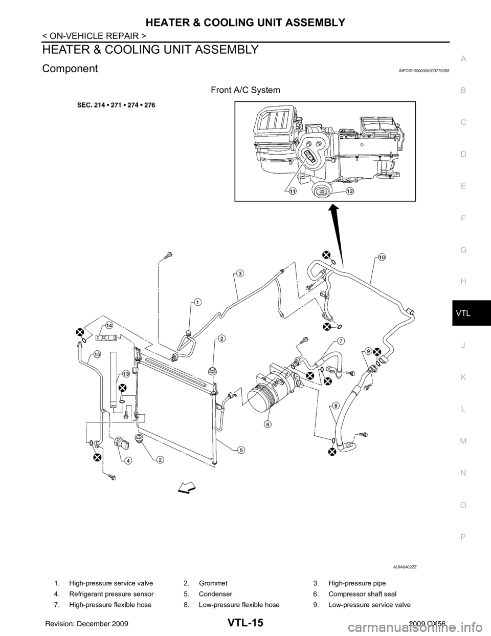
Front A/C System
ALIIA0402ZZ
1. High-pressure service valve 2. Grommet 3. High-pressure pipe
4. Refrigerant pressure sensor 5. Condenser 6. Compressor shaft seal
7. High-pressure flexible hose 8. Low-pressure flexible hose 9. Low-pressure service valve
Revision: December 20092009 QX56
Page 4005 of 4171
WCS-28
< ECU DIAGNOSIS >
COMBINATION METER
ECU DIAGNOSIS
COMBINATION METER
Reference ValueINFOID:0000000004115460
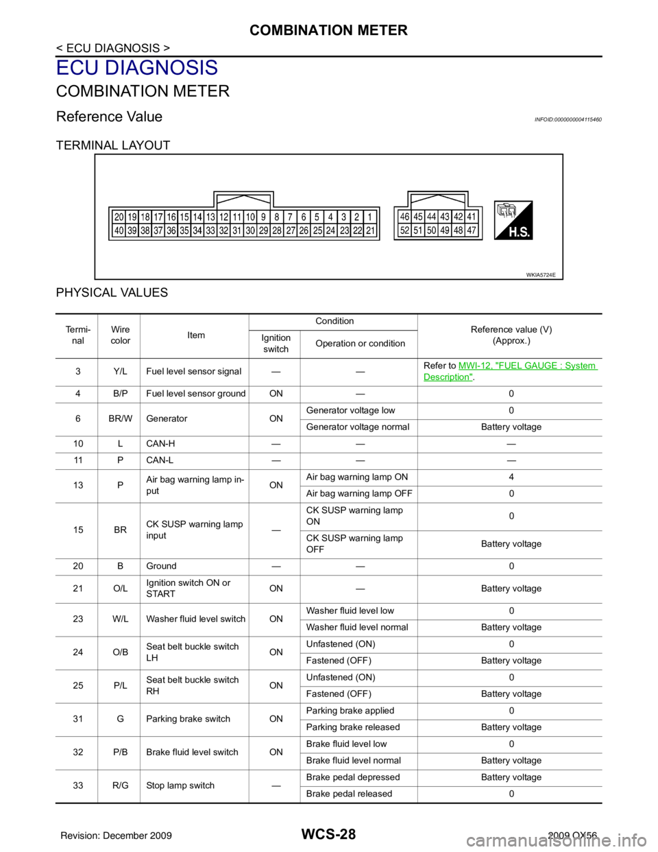
TERMINAL LAYOUT
PHYSICAL VALUES
WKIA5724E
Te r m i -nal Wire
color Item Condition
Reference value (V)
(Approx.)
Ignition
switch Operation or condition
3 Y/L Fuel level sensor signal — —Refer to MWI-12, "
FUEL GAUGE : System
Description".
4 B/P Fuel level sensor ground ON —0
6 BR/W Generator ONGenerator voltage low
0
Generator voltage normal Battery voltage
10 L CAN-H —— —
11 P C A N - L —— —
13 P Air bag warning lamp in-
put ONAir bag warning lamp ON
4
Air bag warning lamp OFF 0
15 BR CK SUSP warning lamp
input —CK SUSP warning lamp
ON
0
CK SUSP warning lamp
OFF Battery voltage
20 B Ground —— 0
21 O/L Ignition switch ON or
START ON
— Battery voltage
23 W/L Washer fluid level switch ON Washer fluid level low
0
Washer fluid level normal Battery voltage
24 O/B Seat belt buckle switch
LH ONUnfastened (ON)
0
Fastened (OFF) Battery voltage
25 P/L Seat belt buckle switch
RH ONUnfastened (ON)
0
Fastened (OFF) Battery voltage
31 G Parking brake switch ON Parking brake applied
0
Parking brake released Battery voltage
32 P/B Brake fluid level switch ON Brake fluid level low
0
Brake fluid level normal Battery voltage
33 R/G Stop lamp switch —Brake pedal depressed
Battery voltage
Brake pedal released 0
Revision: December 20092009 QX56
Page 4029 of 4171
WCS-52
< ECU DIAGNOSIS >
BCM (BODY CONTROL MODULE)
Te r m i n a lWire
color Signal name Signal
input/
output Measuring condition
Reference value or waveform
(Approx.)
Ignition
switch Operation or condition
1BR/W Ignition keyhole illumi-
nation Output OFFDoor is locked (SW OFF)
Battery voltage
Door is unlocked (SW ON) 0V
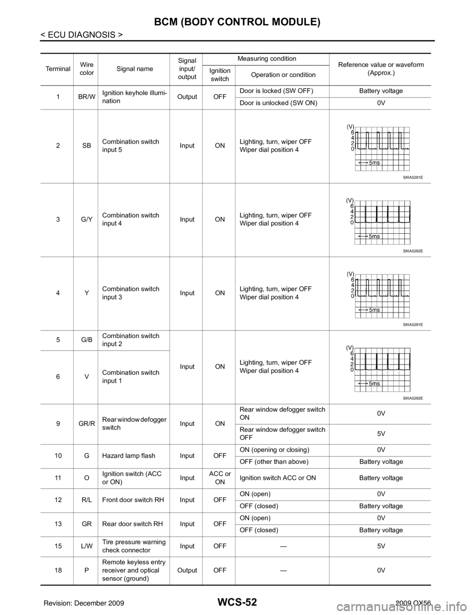
2SB Combination switch
input 5 Input ON
Lighting, turn, wiper OFF
Wiper dial position 4
3G/Y Combination switch
input 4 Input ONLighting, turn, wiper OFF
Wiper dial position 4
4Y Combination switch
input 3 Input ON
Lighting, turn, wiper OFF
Wiper dial position 4
5G/B Combination switch
input 2
Input ONLighting, turn, wiper OFF
Wiper dial position 4
6V Combination switch
input 1
9GR/R Rear window defogger
switch
Input ONRear window defogger switch
ON
0V
Rear window defogger switch
OFF 5V
10 G Hazard lamp flash Input OFF ON (opening or closing)
0V
OFF (other than above) Battery voltage
11 O Ignition switch (ACC
or ON)
InputACC or
ON Ignition switch ACC or ON
Battery voltage
12 R/L Front door switch RH Input OFF ON (open)
0V
OFF (closed) Battery voltage
13 GR Rear door switch RH Input OFF ON (open)
0V
OFF (closed) Battery voltage
15 L/W Tire pressure warning
check connector
Input OFF
—5V
18 P Remote keyless entry
receiver and optical
sensor (ground)
Output OFF
—0V
SKIA5291E
SKIA5292E
SKIA5291E
SKIA5292E
Revision: December 20092009 QX56
Page 4033 of 4171
WCS-56
< ECU DIAGNOSIS >
BCM (BODY CONTROL MODULE)
58 W/R Optical sensorInput ONWhen optical sensor is illumi-
nated
3.1V or more
When optical sensor is not illu-
minated 0.6V or less
59 G Front door lock as-
sembly LH actuator
(unlock) Output OFF
OFF (neutral)
0V
ON (unlock) Battery voltage
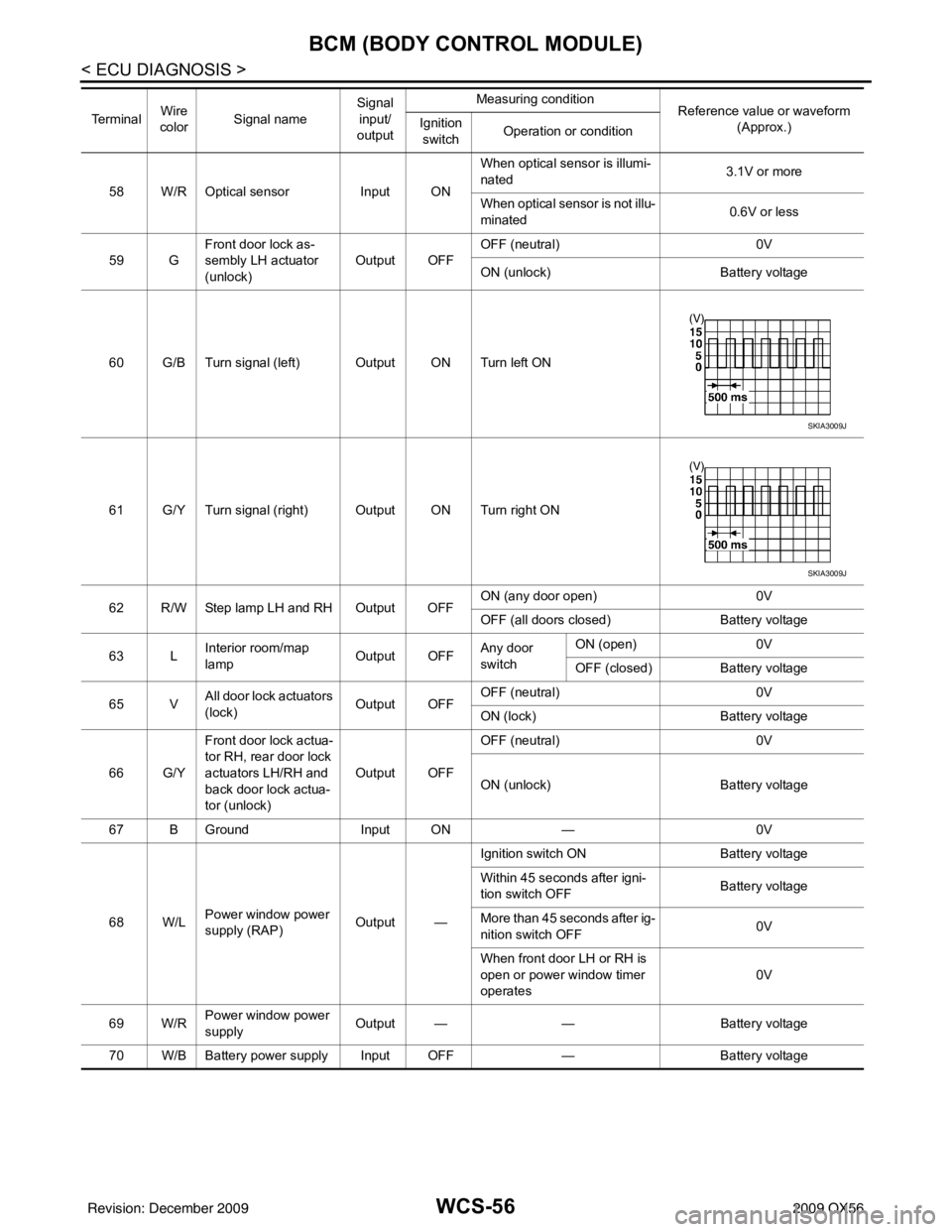
60 G/B Turn signal (left) Output ON Turn left ON
61 G/Y Turn signal (right) Output ON Turn right ON
62 R/W Step lamp LH and RH Output OFF ON (any door open)
0V
OFF (all doors closed) Battery voltage
63 L Interior room/map
lamp Output OFFAny door
switchON (open)
0V
OFF (closed) Battery voltage
65 V All door lock actuators
(lock) Output OFFOFF (neutral)
0V
ON (lock) Battery voltage
66 G/Y Front door lock actua-
tor RH, rear door lock
actuators LH/RH and
back door lock actua-
tor (unlock) Output OFF
OFF (neutral)
0V
ON (unlock) Battery voltage
67 B Ground Input ON—0V
68 W/L Power window power
supply (RAP) Output —Ignition switch ON
Battery voltage
Within 45 seconds after igni-
tion switch OFF Battery voltage
More than 45 seconds after ig-
nition switch OFF 0V
When front door LH or RH is
open or power window timer
operates 0V
69 W/R Power window power
supply
Output —
—Battery voltage
70 W/B Battery power supply Input OFF —Battery voltage
Te r m i n a l
Wire
color Signal name Signal
input/
output Measuring condition
Reference value or waveform
(Approx.)
Ignition
switch Operation or condition
SKIA3009J
SKIA3009J
Revision: December 20092009 QX56
Page 4042 of 4171
WCS
PRECAUTIONSWCS-65
< PRECAUTION >
C
DE
F
G H
I
J
K L
M B A
O P
PRECAUTION
PRECAUTIONS
Precaution for Supplemental Restraint System (SRS) "AIR BAG" and "SEAT BELT
PRE-TENSIONER"
INFOID:0000000005867889
The Supplemental Restraint System such as “AIR BAG” and “SEAT BELT PRE-TENSIONER”, used along
with a front seat belt, helps to reduce the risk or severi ty of injury to the driver and front passenger for certain
types of collision. This system includes seat belt switch inputs and dual stage front air bag modules. The SRS
system uses the seat belt switches to determine the front air bag deployment, and may only deploy one front
air bag, depending on the severity of a collision and w hether the front occupants are belted or unbelted.
Information necessary to service the system safely is included in the SR and SB section of this Service Man-
ual.
WARNING:
• To avoid rendering the SRS inoper ative, which could increase the risk of personal injury or death in
the event of a collision which would result in air bag inflation, all maintenance must be performed by
an authorized NISSAN/INFINITI dealer.
• Improper maintenance, including in correct removal and installation of the SRS, can lead to personal
injury caused by unintentional act ivation of the system. For removal of Spiral Cable and Air Bag
Module, see the SR section.
• Do not use electrical test equipm ent on any circuit related to the SRS unless instructed to in this
Service Manual. SRS wiring harnesses can be identi fied by yellow and/or orange harnesses or har-
ness connectors.
PRECAUTIONS WHEN USING POWER TOOLS (AIR OR ELECTRIC) AND HAMMERS
WARNING:
• When working near the Airbag Diagnosis Sensor Un it or other Airbag System sensors with the Igni-
tion ON or engine running, DO NOT use air or el ectric power tools or strike near the sensor(s) with a
hammer. Heavy vibration could activate the sensor( s) and deploy the air bag(s), possibly causing
serious injury.
• When using air or electric power tools or hammers, always switch the Ignition OFF, disconnect the battery, and wait at least 3 minutes before performing any service.
Revision: December 20092009 QX56
Page 4044 of 4171

WT-2
Hazard Warning Lamps Flash When Ignition
Switch Is Turned On ...............................................
33
"TIRE PRESSURE" INFORMATION IN DIS-
PLAY UNIT DOES NOT EXIST .........................
34
"TIRE PRESSURE" Information in Display Unit
Does Not Exist ..................................................... ...
34
ID REGISTRATION CANNOT BE COMPLET-
ED ......................................................................
35
ID Registration Cannot Be Completed ................ ...35
NOISE, VIBRATION AND HARSHNESS
(NVH) TROUBLESHOOTING ......................... ...
36
NVH Troubleshooting Chart ................................ ...36
PRECAUTION .............................................37
PRECAUTIONS .............................................. ...37
Precaution for Supplemental Restraint System
(SRS) "AIR BAG" and "SEAT BELT PRE-TEN-
SIONER" .............................................................. ...
37
Precaution Necessary for Steering Wheel Rota-
tion After Battery Disconnect ..................................
37
PREPARATION ...........................................39
PREPARATION .............................................. ...39
Special Service Tool ............................................ ...39
Commercial Service Tool ........................................39
ON-VEHICLE MAINTENANCE ..................40
WHEEL ........................................................... ...40
Inspection ............................................................. ...40
ON-VEHICLE REPAIR ...............................41
WHEEL AND TIRE ASSEMBLY .................... ...41
Adjustment ........................................................... ...41
REMOVAL AND INSTALLATION ..............43
REMOVAL AND INSTALLATION .................. ...43
Transmitter (Pressure Sensor) ............................. ...43
SERVICE DATA AND SPECIFICATIONS
(SDS) .......... ................................. ...............
45
SERVICE DATA AND SPECIFICATIONS
(SDS) .............................................................. ...
45
Road Wheel ......................................................... ...45
Tire ..........................................................................45
Revision: December 20092009 QX56
Page 4050 of 4171
WT-8
< FUNCTION DIAGNOSIS >
TPMS
FUNCTION DIAGNOSIS
TPMS
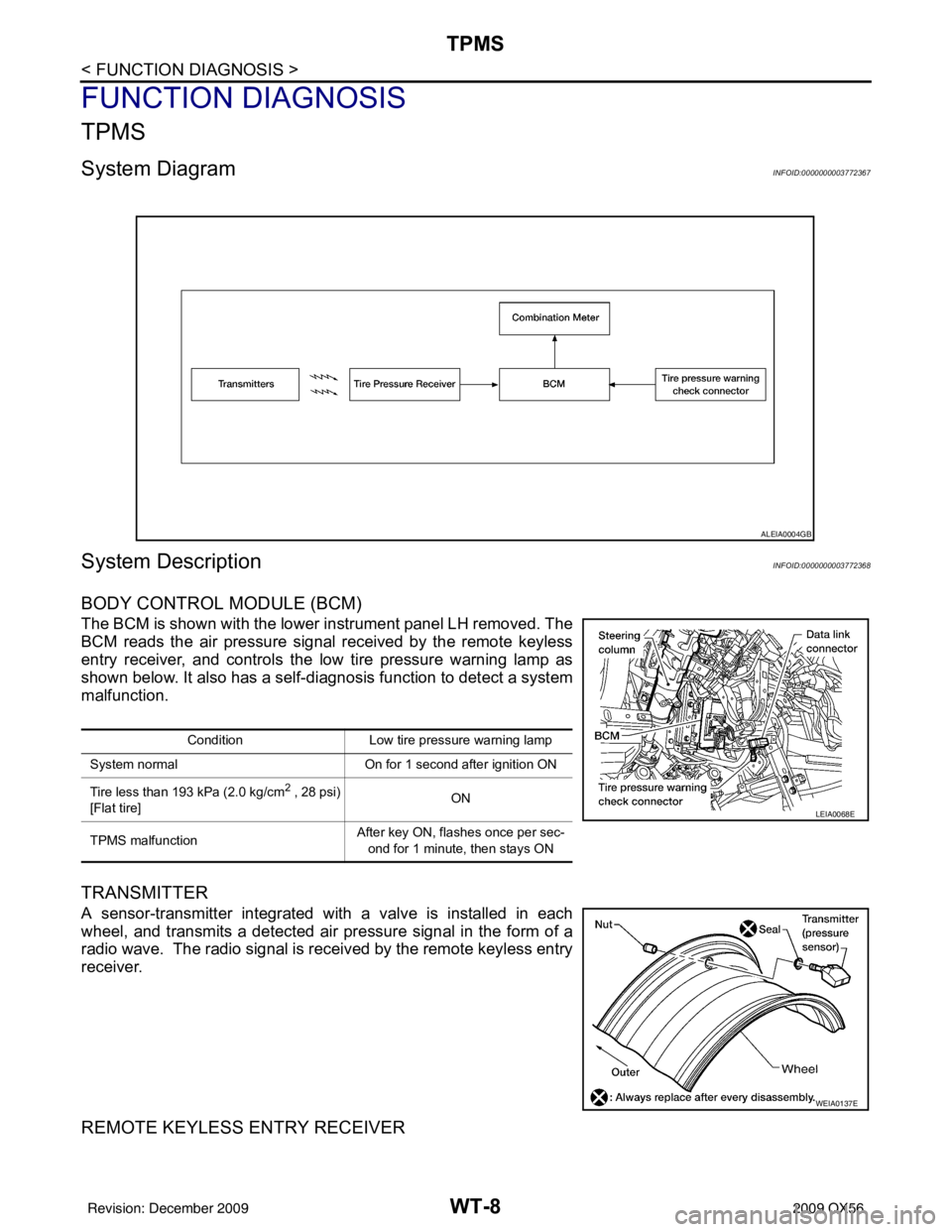
System DiagramINFOID:0000000003772367
System DescriptionINFOID:0000000003772368
BODY CONTROL MODULE (BCM)
The BCM is shown with the lower instrument panel LH removed. The
BCM reads the air pressure signal received by the remote keyless
entry receiver, and controls the low tire pressure warning lamp as
shown below. It also has a self-d iagnosis function to detect a system
malfunction.
TRANSMITTER
A sensor-transmitter integrated with a valve is installed in each
wheel, and transmits a detected air pr essure signal in the form of a
radio wave. The radio signal is received by the remote keyless entry
receiver.
REMOTE KEYLESS ENTRY RECEIVER
ALEIA0004GB
Condition Low tire pressure warning lamp
System normal On for 1 second after ignition ON
Tire less than 193 kPa (2.0 kg/cm
2 , 28 psi)
[Flat tire] ON
TPMS malfunction After key ON, flashes once per sec-
ond for 1 minute, then stays ON
LEIA0068E
WEIA0137E
Revision: December 20092009 QX56
Page 4058 of 4171
WT-16
< COMPONENT DIAGNOSIS >
C1712 - C1715, C1720 - C1723, C1724 - C1727 TRANSMITTER MALFUNCTION
C1712 - C1715, C1720 - C1723, C1724 - C1727 TRANSMITTER MALFUNC-
TION
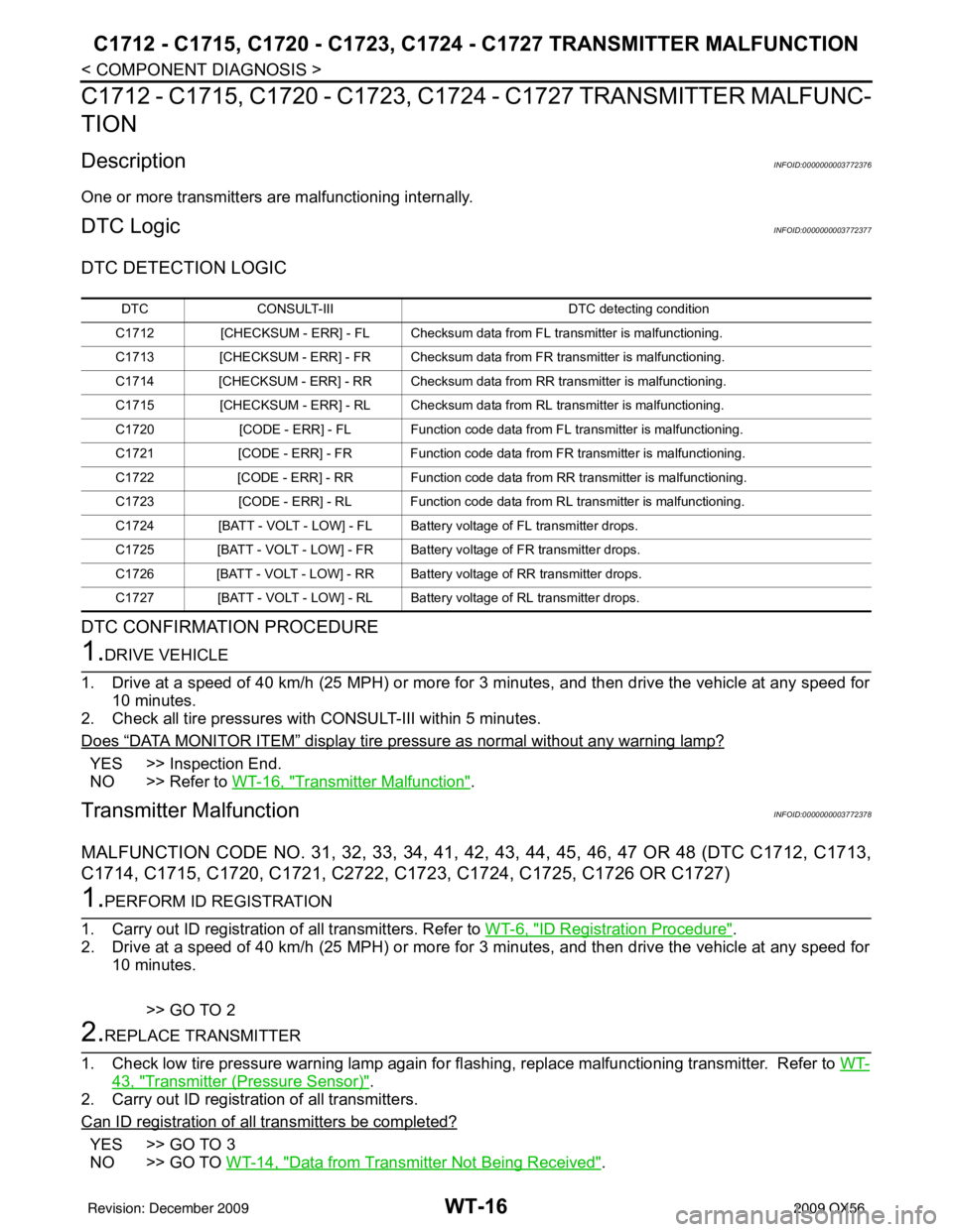
DescriptionINFOID:0000000003772376
One or more transmitters are malfunctioning internally.
DTC LogicINFOID:0000000003772377
DTC DETECTION LOGIC
DTC CONFIRMATION PROCEDURE
1.DRIVE VEHICLE
1. Drive at a speed of 40 km/h (25 MPH) or more fo r 3 minutes, and then drive the vehicle at any speed for
10 minutes.
2. Check all tire pressures with CONSULT-III within 5 minutes.
Does
“DATA MONITOR ITEM” display tire pressure as normal without any warning lamp?
YES >> Inspection End.
NO >> Refer to WT-16, "
Transmitter Malfunction".
Transmitter MalfunctionINFOID:0000000003772378
MALFUNCTION CODE NO. 31, 32, 33, 34, 41, 42, 43, 44, 45, 46, 47 OR 48 (DTC C1712, C1713,
C1714, C1715, C1720, C1721, C2722, C1723, C1724, C1725, C1726 OR C1727)
1.PERFORM ID REGISTRATION
1. Carry out ID registration of all transmitters. Refer to WT-6, "
ID Registration Procedure".
2. Drive at a speed of 40 km/h (25 MPH) or more fo r 3 minutes, and then drive the vehicle at any speed for
10 minutes.
>> GO TO 2
2.REPLACE TRANSMITTER
1. Check low tire pressure warning lamp again for fl ashing, replace malfunctioning transmitter. Refer to WT-
43, "Transmitter (Pressure Sensor)".
2. Carry out ID registration of all transmitters.
Can ID registration of all transmitters be completed?
YES >> GO TO 3
NO >> GO TO WT-14, "
Data from Transmitter Not Being Received".
DTC CONSULT-III DTC detecting condition
C1712 [CHECKSUM - ERR] - FL Checksum data from FL transmitter is malfunctioning.
C1713 [CHECKSUM - ERR] - FR Checksum data from FR transmitter is malfunctioning.
C1714 [CHECKSUM - ERR] - RR Checksum data from RR transmitter is malfunctioning.
C1715 [CHECKSUM - ERR] - RL Ch ecksum data from RL transmitter is malfunctioning.
C1720 [CODE - ERR] - FL Function code data from FL transmitter is malfunctioning.
C1721 [CODE - ERR] - FR Function code data from FR transmitter is malfunctioning.
C1722 [CODE - ERR] - RR Function code data from RR transmitter is malfunctioning.
C1723 [CODE - ERR] - RL Function code data from RL transmitter is malfunctioning.
C1724 [BATT - VOLT - LOW] - FL Battery voltage of FL transmitter drops.
C1725 [BATT - VOLT - LOW] - FR Battery voltage of FR transmitter drops.
C1726 [BATT - VOLT - LOW] - RR Battery voltage of RR transmitter drops.
C1727 [BATT - VOLT - LOW] - RL Battery voltage of RL transmitter drops.
Revision: December 20092009 QX56