Page 3482 of 4171
SPIRAL CABLESR-9
< ON-VEHICLE REPAIR >
C
DE
F
G
I
J
K L
M A
B
SR
N
O P
• The spiral cable may snap du e to steering operation if the
cable is not installed in the correct position.
• With the steering linkage disconnected, the cable may snap
by turning the steering wheel beyond the limited number of
turns. The spiral cable can be turned counterclockwise about
2.5 turns from the neutral position.
PHIA0275E
Revision: December 20092009 QX56
Page 3609 of 4171
ST-18
< REMOVAL AND INSTALLATION >
STEERING WHEEL
REMOVAL AND INSTALLATION
STEERING WHEEL
Removal and InstallationINFOID:0000000004187593
REMOVAL
1. Set the front wheels in the straight-ahead position.
2. Remove the driver air bag module. Refer to SR-5, "Removal and Installation"
.
3. Disconnect steering wheel switches.
4. Remove the steering wheel center nut.
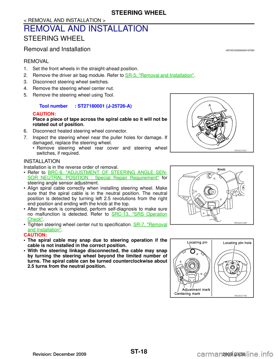
5. Remove the steering wheel using Tool.
CAUTION:
Place a piece of tape across the sp iral cable so it will not be
rotated out of position.
6. Disconnect heated steering wheel connector.
7. Inspect the steering wheel near the puller holes for damage. If damaged, replace the steering wheel.
Remove steering wheel rear cover and steering wheelswitches, if required.
INSTALLATION
Installation is in the reverse order of removal.
Refer to BRC-8, "ADJUSTMENT OF STEERING ANGLE SEN-
SOR NEUTRAL POSITION : Special Repair Requirement" for
steering angle sensor adjustment.
Align spiral cable correctly when installing steering wheel. Make sure that the spiral cable is in the neutral position. The neutral
position is detected by turning left 2.5 revolutions from the right
end position and ending with the knob at the top.
After the work is completed, perform self-diagnosis to make sure no malfunction is detected. Refer to SRC-13, "SRS Operation
Check".
Tighten steering wheel center nut to specification. SR-7, "Removal
and Installation".
CAUTION:
The spiral cable may snap due to steering operation if the
cable is not installed in the correct position.
With the steering linkage di sconnected, the cable may snap
by turning the steering wheel beyond the limited number of
turns. The spiral cable can be turned counterclockwise about
2.5 turns from the neutral position. Tool number : ST27180001 (J-25726-A)
SGIA1524J
WGIA0038E
PHIA0275E
Revision: December 20092009 QX56
Page 3863 of 4171
TRANSMISSION ASSEMBLYTM-215
< REMOVAL AND INSTALLATION >
CEF
G H
I
J
K L
M A
B
TM
N
O P
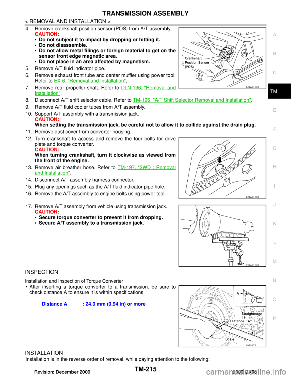
4. Remove crankshaft position sensor (POS) from A/T assembly. CAUTION:
Do not subject it to impact by dropping or hitting it.
Do not disassemble.
Do not allow metal filings or foreign material to get on the
sensor front edge magnetic area.
Do not place in an area affected by magnetism.
5. Remove A/T fluid indicator pipe.
6. Remove exhaust front tube and center muffler using power tool. Refer to EX-6, "Removal and Installation"
.
7. Remove rear propeller shaft. Refer to DLN-196, "Removal and
Installation".
8. Disconnect A/T shift selector cable. Refer to TM-196, "A/T Shift Selector Removal and Installation"
.
9. Remove A/T fluid cooler tubes from A/T assembly.
10. Support A/T assembly with a transmission jack. CAUTION:
When setting the transmission jack, be careful not to allow it to collide against the drain plug.
11. Remove dust cover from converter housing.
12. Turn crankshaft to access and remove the four bolts for drive plate and torque converter.
CAUTION:
When turning crankshaft, turn it clockwise as viewed from
the front of the engine.
13. Remove air breather hose. Refer to TM-197, "2WD : Removal
and Installation".
14. Disconnect A/T assembly harness connector.
15. Plug any openings such as the A/T fluid indicator pipe hole.
16. Remove the A/T assembly to engine bolts using power tool.
17. Remove A/T assembly from vehicle using transmission jack. CAUTION:
Secure torque converter to prevent it from dropping.
Secure A/T assembly to a transmission jack.
INSPECTION
Installation and Inspection of Torque Converter
After inserting a torque converter to a transmission, be sure to check distance A to ensure it is within specifications.
INSTALLATION
Installation is in the reverse order of removal, while paying attention to the following:
LCIA0334E
LCIA0335E
SCIA0499E
Distance A : 24.0 mm (0.94 in) or more
SAT017B
Revision: December 20092009 QX56
Page 3864 of 4171
TM-216
< REMOVAL AND INSTALLATION >
TRANSMISSION ASSEMBLY
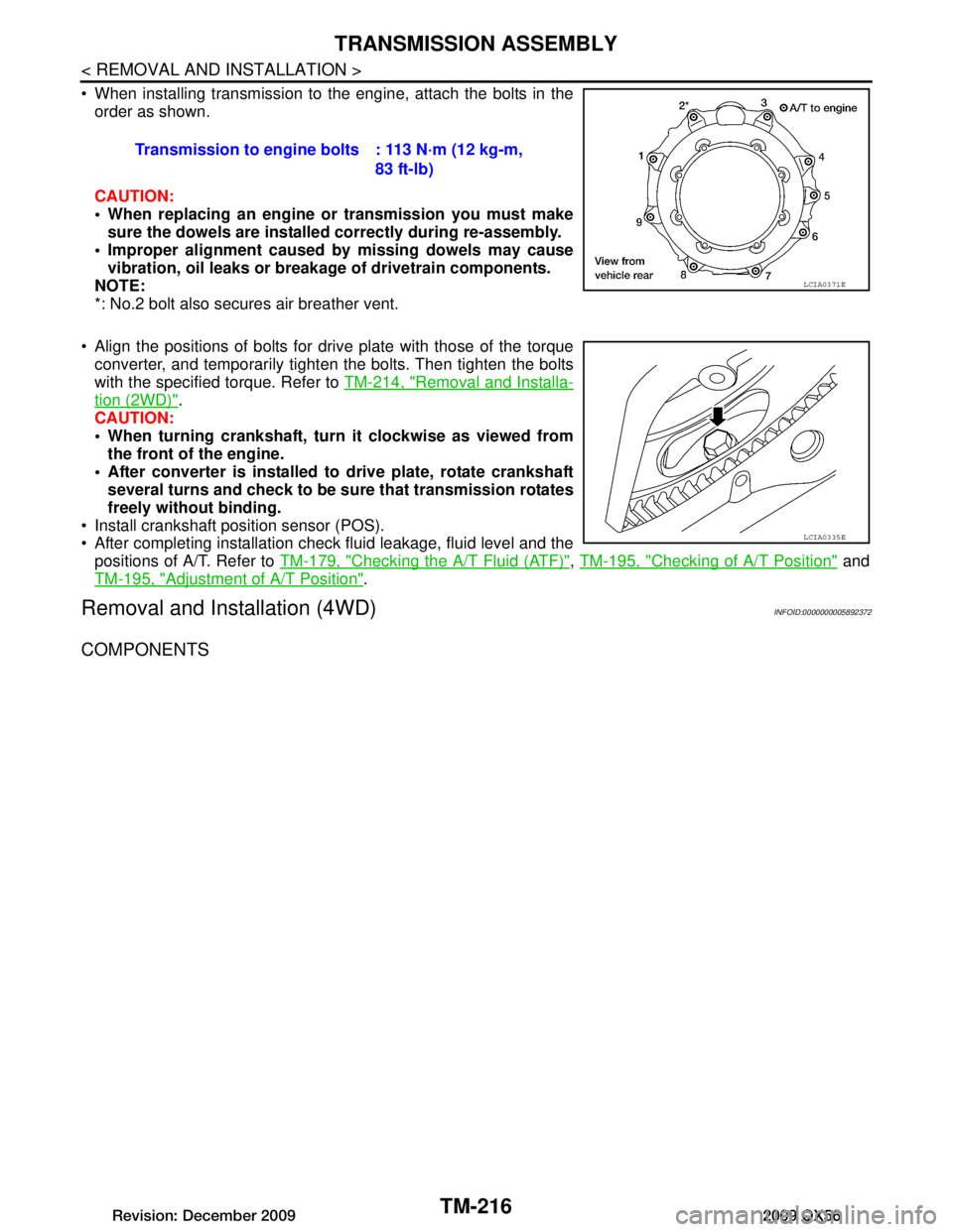
When installing transmission to the engine, attach the bolts in theorder as shown.
CAUTION:
When replacing an engine or transmission you must make
sure the dowels are installe d correctly during re-assembly.
Improper alignment caused by missing dowels may cause
vibration, oil leaks or breakage of drivetrain components.
NOTE:
*: No.2 bolt also secures air breather vent.
Align the positions of bolts for drive plate with those of the torque converter, and temporarily tight en the bolts. Then tighten the bolts
with the specified torque. Refer to TM-214, "Removal and Installa-
tion (2WD)".
CAUTION:
When turning crankshaft, turn it clockwise as viewed from
the front of the engine.
After converter is installed to drive plate, rotate crankshaft several turns and check to be su re that transmission rotates
freely without binding.
Install crankshaft position sensor (POS).
After completing installation check fluid leakage, fluid level and the positions of A/T. Refer to TM-179, "Checking the A/T Fluid (ATF)"
, TM-195, "Checking of A/T Position" and
TM-195, "Adjustment of A/T Position"
.
Removal and Installation (4WD)INFOID:0000000005892372
COMPONENTS
Transmission to engine bolts : 113 N·m (12 kg-m,
83 ft-lb)
LCIA0371E
LCIA0335E
Revision: December 20092009 QX56
Page 3866 of 4171
TM-218
< REMOVAL AND INSTALLATION >
TRANSMISSION ASSEMBLY
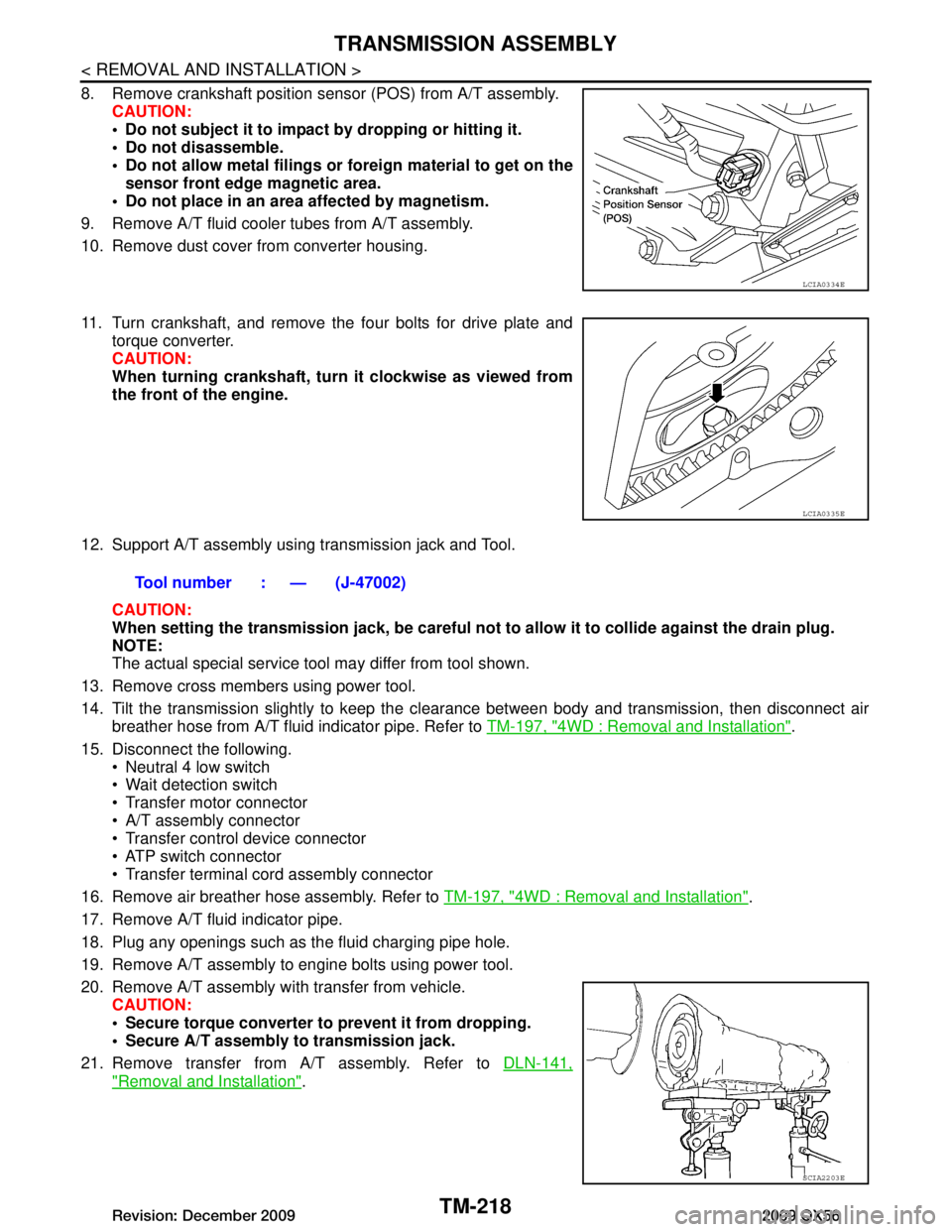
8. Remove crankshaft position sensor (POS) from A/T assembly.CAUTION:
Do not subject it to impact by dropping or hitting it.
Do not disassemble.
Do not allow metal filings or fo reign material to get on the
sensor front edge magnetic area.
Do not place in an area affected by magnetism.
9. Remove A/T fluid cooler tubes from A/T assembly.
10. Remove dust cover from converter housing.
11. Turn crankshaft, and remove the four bolts for drive plate and torque converter.
CAUTION:
When turning crankshaft, turn it clockwise as viewed from
the front of the engine.
12. Support A/T assembly using transmission jack and Tool. CAUTION:
When setting the transmission jack, be careful not to allow it to collide against the drain plug.
NOTE:
The actual special service tool may differ from tool shown.
13. Remove cross members using power tool.
14. Tilt the transmission slightly to keep the cl earance between body and transmission, then disconnect air
breather hose from A/T fluid indicator pipe. Refer to TM-197, "4WD : Removal and Installation"
.
15. Disconnect the following. Neutral 4 low switch
Wait detection switch
Transfer motor connector
A/T assembly connector
Transfer control device connector
ATP switch connector
Transfer terminal cord assembly connector
16. Remove air breather hose assembly. Refer to TM-197, "4WD : Removal and Installation"
.
17. Remove A/T fluid indicator pipe.
18. Plug any openings such as the fluid charging pipe hole.
19. Remove A/T assembly to engine bolts using power tool.
20. Remove A/T assembly with transfer from vehicle. CAUTION:
Secure torque converter to prevent it from dropping.
Secure A/T assembly to transmission jack.
21. Remove transfer from A/T assembly. Refer to DLN-141,
"Removal and Installation".
LCIA0334E
LCIA0335E
Tool number : — (J-47002)
SCIA2203E
Revision: December 20092009 QX56
Page 3867 of 4171
TRANSMISSION ASSEMBLYTM-219
< REMOVAL AND INSTALLATION >
CEF
G H
I
J
K L
M A
B
TM
N
O P
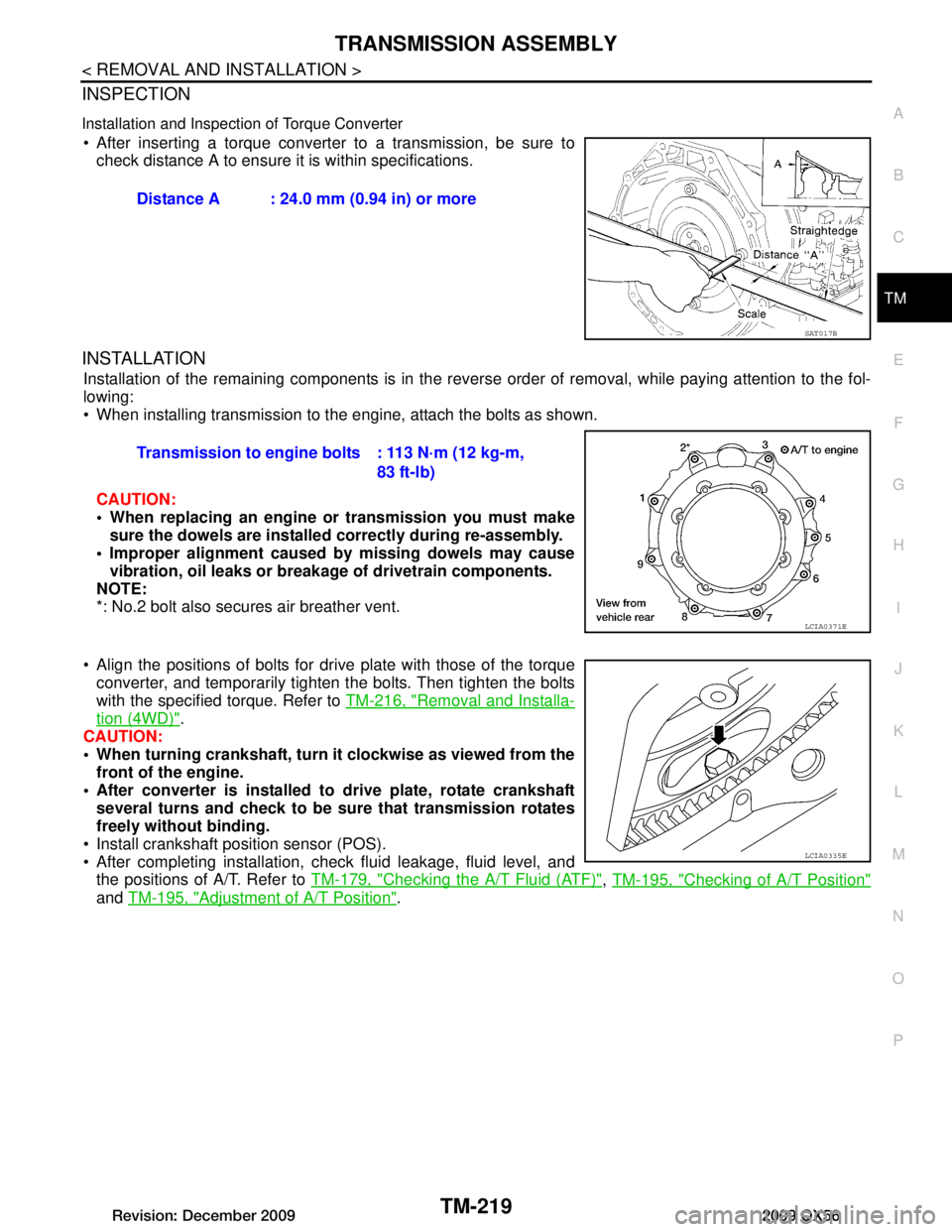
INSPECTION
Installation and Inspection of Torque Converter
After inserting a torque converter to a transmission, be sure to check distance A to ensure it is within specifications.
INSTALLATION
Installation of the remaining components is in the revers e order of removal, while paying attention to the fol-
lowing:
When installing transmission to the engine, attach the bolts as shown.
CAUTION:
When replacing an engine or transmission you must make sure the dowels are installed correctly during re-assembly.
Improper alignment caused by missing dowels may cause vibration, oil leaks or breakage of drivetrain components.
NOTE:
*: No.2 bolt also secures air breather vent.
Align the positions of bolts for dr ive plate with those of the torque
converter, and temporarily tighten the bolts. Then tighten the bolts
with the specified torque. Refer to TM-216, "Removal and Installa-
tion (4WD)".
CAUTION:
When turning crankshaft, turn it clockwise as viewed from the
front of the engine.
After converter is installed to drive plate, rotate crankshaft
several turns and check to be sure that transmission rotates
freely without binding.
Install crankshaft position sensor (POS).
After completing installation, check fluid leakage, fluid level, and the positions of A/T. Refer to TM-179, "Checking the A/T Fluid (ATF)"
, TM-195, "Checking of A/T Position"
and TM-195, "Adjustment of A/T Position".
Distance A : 24.0 mm (0.94 in) or more
SAT017B
Transmission to engine bolts : 113 N·m (12 kg-m,
83 ft-lb)
LCIA0371E
LCIA0335E
Revision: December 20092009 QX56
Page 3880 of 4171
TM-232
< DISASSEMBLY AND ASSEMBLY >
DISASSEMBLY
DISASSEMBLY
DisassemblyINFOID:0000000004187489
CAUTION:
Do not disassemble parts behind Drum Support. Refer to TM-8, "Cross-Sectional View (2WD models)"
.
1. Drain A/T fluid through drain plug.
2. Remove torque converter by holding it firmly and turing while pulling straight out.
3. Check torque converter one-way clutch using a check tool as shown.
a. Insert a check tool into the groove of bearing support built into one-way clutch outer race.
b. While holding bearing support with a check tool, rotate one-way clutch spline using suitable tool.
c. Make sure that inner race rotates clockwise only. If not, replace torque converter assembly.
4. Remove bolts and converter housing from transmission case. CAUTION:
Do not scratch converter housing.
Self-sealing bolt (A)
SCIA5010E
SCIA3171E
WCIA0662E
Revision: December 20092009 QX56
Page 3950 of 4171
VTL-10
< ON-VEHICLE REPAIR >
OPTICAL SENSOR
OPTICAL SENSOR
Removal and InstallationINFOID:0000000003775263
REMOVAL
1. Remove the defroster grille from the instrument panel. Refer to VTL-33, "Removal and Installation".
2. Disconnect the optical sensor connector (2).
3. Twist the optical sensor (1) counter clockwise to remove it from the defroster grille.
INSTALLATION
Installation is in the reverse order of removal.
ALIIA0061ZZ
Revision: December 20092009 QX56