Page 2762 of 4171
MWI-40
< COMPONENT DIAGNOSIS >
CLOCK
CLOCK
Wiring DiagramINFOID:0000000003776652
ALNWA0134GB
Revision: December 20092009 QX56
Page 2763 of 4171
MWI
CLOCKMWI-41
< COMPONENT DIAGNOSIS >
C
DE
F
G H
I
J
K L
M B A
O P
ABNIA0401GB
Revision: December 20092009 QX56
Page 2790 of 4171

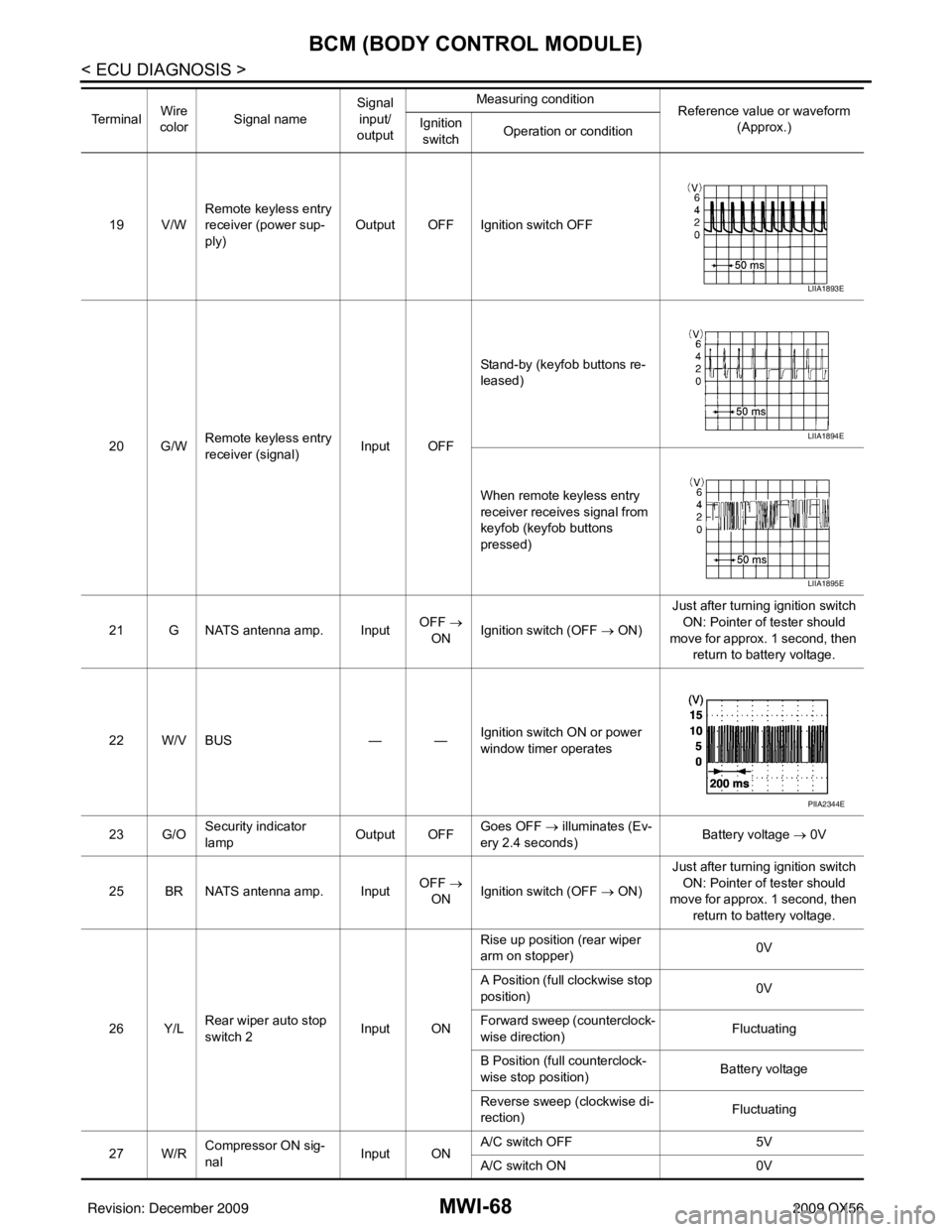
MWI-68
< ECU DIAGNOSIS >
BCM (BODY CONTROL MODULE)
19 V/WRemote keyless entry
receiver (power sup-
ply) Output OFF Ignition switch OFF
20 G/W Remote keyless entry
receiver (signal) Input OFFStand-by (keyfob buttons re-
leased)
When remote keyless entry
receiver receives signal from
keyfob (keyfob buttons
pressed)
21 G NATS antenna amp. Input OFF
→
ON Ignition switch (OFF
→ ON)Just after turning ignition switch
ON: Pointer of tester should
move for approx. 1 second, then return to battery voltage.
22 W/V BUS — —Ignition switch ON or power
window timer operates
23 G/O Security indicator
lamp Output OFF
Goes OFF
→ illuminates (Ev-
ery 2.4 seconds) Battery voltage
→ 0V
25 BR NATS antenna amp. Input OFF
→
ON Ignition switch (OFF
→ ON)Just after turning ignition switch
ON: Pointer of tester should
move for approx. 1 second, then return to battery voltage.
26 Y/L Rear wiper auto stop
switch 2 Input ONRise up position (rear wiper
arm on stopper)
0V
A Position (full clockwise stop
position) 0V
Forward sweep (counterclock-
wise direction) Fluctuating
B Position (full counterclock-
wise stop position) Battery voltage
Reverse sweep (clockwise di-
rection) Fluctuating
27 W/R Compressor ON sig-
nal Input ONA/C switch OFF
5V
A/C switch ON 0V
Te r m i n a l
Wire
color Signal name Signal
input/
output Measuring condition
Reference value or waveform
(Approx.)
Ignition
switch Operation or condition
LIIA1893E
LIIA1894E
LIIA1895E
PIIA2344E
Revision: December 20092009 QX56
Page 2792 of 4171

MWI-70
< ECU DIAGNOSIS >
BCM (BODY CONTROL MODULE)
44 ORear wiper auto stop
switch 1 Input ONRise up position (rear wiper
arm on stopper)
0V
A Position (full clockwise stop
position) Battery voltage
Forward sweep (counterclock-
wise direction) Fluctuating
B Position (full counterclock-
wise stop position) 0V
Reverse sweep (clockwise di-
rection) Fluctuating
47 SB Front door switch LH Input OFF ON (open)
0V
OFF (closed) Battery voltage
48 R/Y Rear door switch LH Input OFF ON (open)
0V
OFF (closed) Battery voltage
49 R Cargo lamp Output OFFAny door open (ON)
0V
All doors closed (OFF) Battery voltage
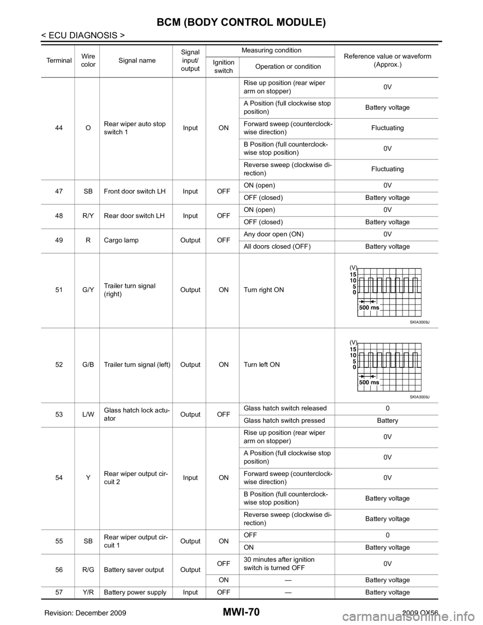
51 G/Y Trailer turn signal
(right) Output ON Turn right ON
52 G/B Trailer turn signal (l eft) Output ON Turn left ON
53 L/W Glass hatch lock actu-
ator
Output OFFGlass hatch switch released
0
Glass hatch switch pressed Battery
54 Y Rear wiper output cir-
cuit 2 Input ONRise up position (rear wiper
arm on stopper)
0V
A Position (full clockwise stop
position) 0V
Forward sweep (counterclock-
wise direction) 0V
B Position (full counterclock-
wise stop position) Battery voltage
Reverse sweep (clockwise di-
rection) Battery voltage
55 SB Rear wiper output cir-
cuit 1 Output ONOFF
0
ON Battery voltage
56 R/G Battery saver output Output OFF
30 minutes after ignition
switch is turned OFF 0V
ON — Battery voltage
57 Y/R Battery power supply Input OFF —Battery voltage
Te r m i n a l
Wire
color Signal name Signal
input/
output Measuring condition
Reference value or waveform
(Approx.)
Ignition
switch Operation or condition
SKIA3009J
SKIA3009J
Revision: December 20092009 QX56
Page 2825 of 4171
MWI
CLOCK
MWI-103
< ON-VEHICLE REPAIR >
C
D E
F
G H
I
J
K L
M B A
O P
CLOCK
Removal and InstallationINFOID:0000000003776686
REMOVAL
1. Remove the cluster lid C lower. Refer to IP-16, "Removal and Installation".
2. Detach the clock (1) from the tabs (A) and remove clock (1).
INSTALLATION
Installation is in the reverse order of removal.
ALNIA0661ZZ
Revision: December 20092009 QX56
Page 2915 of 4171

PG-44
< COMPONENT DIAGNOSIS >
HARNESS
A3 M6 W/10 : To E10A3 M82 W/2 : Circuit breaker-2
A2 M7 B/5 : Passenger select unlock relay G4 M84 W/16 : To B101
A3 M8 W/16 : To D2 A3 M85 W/3 : Tilt motor assembly
A2 M9 BR/24 : To D1 B3 M86 W/2 : Tilt motor assembly
A3 M10 Y/4 : To E29 B3 M87 B/5 : Rear power vent window relay (open)
A3 M11 B/1 : Parking brake switch B3 M89 B/5 : Rear power vent window relay (close)
C3 M12 GR/6 : Key switch and ignition knob switch B3 M91 W/16 : To E26
D3 M13 BR/2 : Front passenger air bag OFF indicator A2 M92 B/6 : Power liftgate switch
A2 M14 GR/6 : Diode-3 D1 M93 W/24 : Display unit
B3 M15 W/4 : Steering lock solenoid A2 M95 W/6 : Rear power vent window switch
A2 M16 GR/6 : ADP steering switch A2 M96 BR/6 : Pedal adjusting switch
B2 M17 W/8 : Steering angle sensor C2 M98 W/16 : A/C and AV switch assembly
C2 M18 W/40 : BCM (body control module) C3 M99 BR/2 : Foot lamp LH
C2 M19 W/15 : BCM (body control module) F4 M100 BR/2 : Foot lamp RH
C2 M20 B/15 : BCM (body control module) E3 M104 W/4 : Aux jack
C3 M21 W/4 : NATS antenna AMP. F2 M105 Y/2 : Front passenger air bag module
C3 M22 W/16 : Data link connector F2 M106 O/2 : Front passenger air bag module
B1 M23 W/12 : Combination meter F3 M107 B/5 : Front blower relay
C1 M24 W/40 : Combination meter D5 M108 B/6 : Yaw rate/ side/ decel G sensor
F2 M25 B/4 : Remote keyless entry receiver A1 M109 BR/2 : Front tweeter LH
B2 M26 W/6 : Ignition switch D2 M110 BR/2 : Center speaker
B2 M28 W/16 : Combination switch F2 M111 BR/2 : Front tweeter RH
B2 M29 Y/6 : Combination switch (spiral cable) C2 M112 BR/14 : BOSE speaker amp.
B3 M30 GR/8 : Combination switch (spiral cable) C2 M113 BR/23 : BOSE speaker amp.
G4 M31 SMJ : To E152 A2 M116 GR/8 : Sonar system OFF switch
C3 M32 W/4 : In-vehicle sensor A2 M117 GR/8 : Rear sonar system OFF switch
B3 M33 W/32 : Automatic drive position control unit B1 M118 B/2 : Front sonar buzzer
B3 M34 W/16 : Automatic drive position control unit F2 M120 W/4 : Remote keyless entry receiver
C5 M35 Y/28 : Air bag diagnosis sensor unit F4 M122 W/4 : Variable blower control (front)
G4 M36 SMJ : To B149 C3 M123 W/2 : Tire pressure warning check connector
G3 M37 B/1 : Fuse block (J/B) D2 M139 B/2 : Diode-1
G3 M38 B/2 : Fuse block (J/B) D1 M140 B/2 : Diode-2
D3 M39 W/8 : Fuse block (J/B) C2 M141 GR/8 : 4WD shift switch
A3 M40 SMJ : To B69 E1 M142 B/6 : Mode door motor (front)
D2 M42 W/20 : AV control unit E3 M143 B/6 : Air mix door motor (passenger)
D2 M43 W/12 : AV control unit C1 M144 B/6 : Defroster door motor
D2 M44 W/32 : AV control unit E3 M146 GR/2 : Intake sensor
D3 M45 W/40 : AV control unit D3 M147B/6 : Air mix doo r motor (driver)
B1 M47 B/2 : Sonar buzzer D2 M148 W/4 : Headlamp aiming switch
D2 M49 B/26 : A/C auto amp. D3 M149 W/4 : Clock
D2 M50 L/26 : A/C auto amp. B1 M150 W/2 : Ignition keyhole illumination
B3 M51 L/4 : Trailer tow relay 1 A3 M158 W/10 : To D3
B2 M52 W/2 : Combination switch (spiral cable) Console sub-harness
D3 M53 B/3 : Front power socket LH D4 M201 W/16 : To M56
E3 M54 B/3 : Front power socket RH (for cigarette
lighter) D4 M202 BR/24 : To M64
Revision: December 20092009 QX56
Page 3006 of 4171

PWC-58
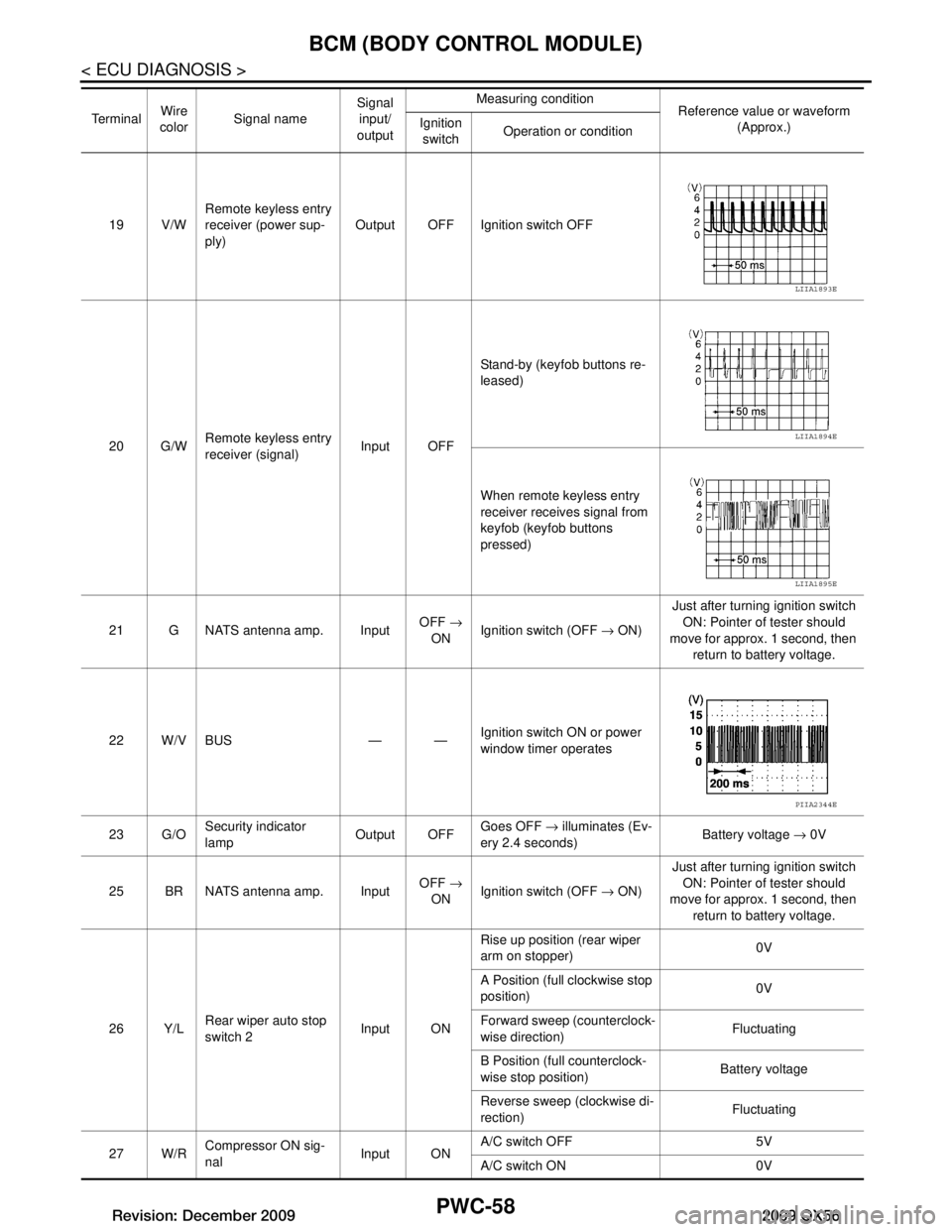
< ECU DIAGNOSIS >
BCM (BODY CONTROL MODULE)
19 V/WRemote keyless entry
receiver (power sup-
ply) Output OFF Ignition switch OFF
20 G/W Remote keyless entry
receiver (signal) Input OFFStand-by (keyfob buttons re-
leased)
When remote keyless entry
receiver receives signal from
keyfob (keyfob buttons
pressed)
21 G NATS antenna amp. Input OFF
→
ON Ignition switch (OFF
→ ON) Just after turning ignition switch
ON: Pointer of tester should
move for approx. 1 second, then return to battery voltage.
22 W/V BUS — — Ignition switch ON or power
window timer operates
23 G/O Security indicator
lamp Output OFF
Goes OFF
→ illuminates (Ev-
ery 2.4 seconds) Battery voltage
→ 0V
25 BR NATS antenna amp. Input OFF
→
ON Ignition switch (OFF
→ ON) Just after turning ignition switch
ON: Pointer of tester should
move for approx. 1 second, then return to battery voltage.
26 Y/L Rear wiper auto stop
switch 2 Input ONRise up position (rear wiper
arm on stopper)
0V
A Position (full clockwise stop
position) 0V
Forward sweep (counterclock-
wise direction) Fluctuating
B Position (full counterclock-
wise stop position) Battery voltage
Reverse sweep (clockwise di-
rection) Fluctuating
27 W/R Compressor ON sig-
nal Input ONA/C switch OFF 5V
A/C switch ON 0V
Te r m i n a l
Wire
color Signal name Signal
input/
output Measuring condition
Reference value or waveform
(Approx.)
Ignition
switch Operation or condition
LIIA1893E
LIIA1894E
LIIA1895E
PIIA2344E
Revision: December 20092009 QX56
Page 3008 of 4171

PWC-60
< ECU DIAGNOSIS >
BCM (BODY CONTROL MODULE)
44 ORear wiper auto stop
switch 1 Input ONRise up position (rear wiper
arm on stopper)
0V
A Position (full clockwise stop
position) Battery voltage
Forward sweep (counterclock-
wise direction) Fluctuating
B Position (full counterclock-
wise stop position) 0V
Reverse sweep (clockwise di-
rection) Fluctuating
47 SB Front door switch LH Input OFF ON (open) 0V
OFF (closed) Ba
ttery voltage
48 R/Y Rear door switch LH Input OFF ON (open) 0V
OFF (closed) Ba
ttery voltage
49 R Cargo lamp Output OFF Any door open (ON) 0V
All doors closed (OFF) Battery voltage
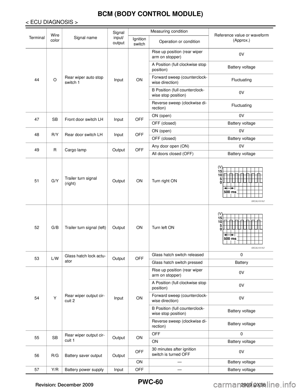
51 G/Y Trailer turn signal
(right) Output ON Turn right ON
52 G/B Trailer turn signal (l eft) Output ON Turn left ON
53 L/W Glass hatch lock actu-
ator
Output OFFGlass hatch switch released 0
Glass hatch switch pressed Battery
54 Y Rear wiper output cir-
cuit 2 Input ONRise up position (rear wiper
arm on stopper)
0V
A Position (full clockwise stop
position) 0V
Forward sweep (counterclock-
wise direction) 0V
B Position (full counterclock-
wise stop position) Battery voltage
Reverse sweep (clockwise di-
rection) Battery voltage
55 SB Rear wiper output cir-
cuit 1 Output ONOFF 0
ON Battery voltage
56 R/G Battery saver output Output OFF
30 minutes after ignition
switch is turned OFF 0V
ON — Battery voltage
57 Y/R Battery power supply Input OFF — Battery voltage
Te r m i n a l
Wire
color Signal name Signal
input/
output Measuring condition
Reference value or waveform
(Approx.)
Ignition
switch Operation or condition
SKIA3009J
SKIA3009J
Revision: December 20092009 QX56