Page 3974 of 4171

VTL-34
< ON-VEHICLE REPAIR >
DUCTS AND GRILLES
REAR OVERHEAD DUCTS
Removal
1. Remove the luggage side finisher lower RH. Refer to INT-19, "Removal and Installation".
2. Remove the headliner. Refer to INT-17, "
Removal and Installation".
NOTE:
The rear headliner duct connected to the rear overhead duct is part of the headlining trim panel and is
replaced as an assembly.
3. Remove the two bolts and remove the rear upper and lower overhead ducts.
Installation
Installation is in the reverse order of removal.
REAR FLOOR DUCT
Removal
1. Remove the luggage side finisher lower RH. Refer to INT-19, "Removal and Installation".
2. Reposition the floor carpet out of the way.
3. Remove the two bolts and remove the rear floor duct.
Installation
Installation is in the reverse order of removal.
GRILLES
Removal
1. Remove the interior trim panels as necessary. Refer to IP-13, "Removal and Installation" or INT-14,
"Removal and Installation".
2. Remove the grille from the interior trim panel. NOTE:
To remove the rear roof console grilles, turn the gr ille counter-clockwise to release the grille from the rear
roof console.
Installation
Installation is in the reverse order of removal.
Revision: December 20092009 QX56
Page 4030 of 4171

WCS
BCM (BODY CONTROL MODULE)WCS-53
< ECU DIAGNOSIS >
C
DE
F
G H
I
J
K L
M B A
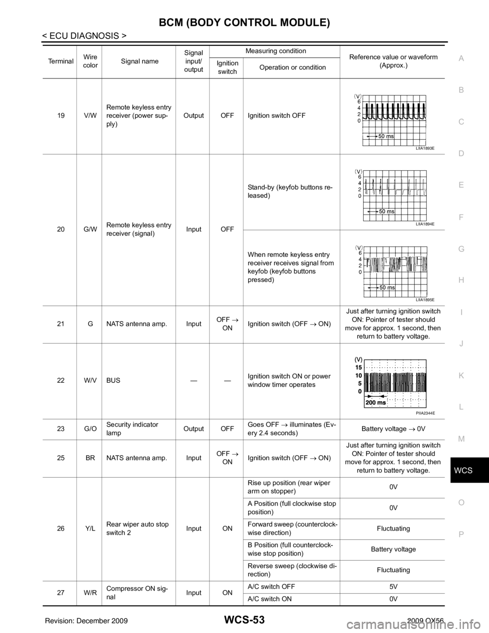
O P19 V/W Remote keyless entry
receiver (power sup-
ply) Output OFF Ignition switch OFF
20 G/W Remote keyless entry
receiver (signal) Input OFFStand-by (keyfob buttons re-
leased)
When remote keyless entry
receiver receives signal from
keyfob (keyfob buttons
pressed)
21 G NATS antenna amp. Input OFF
→
ON Ignition switch (OFF → ON) Just after turning ignition switch
ON: Pointer of tester should
move for approx. 1 second, then return to battery voltage.
22 W/V BUS — —Ignition switch ON or power
window timer operates
23 G/O Security indicator
lamp Output OFF
Goes OFF
→ illuminates (Ev-
ery 2.4 seconds) Battery voltage
→ 0V
25 BR NATS antenna amp. Input OFF
→
ON Ignition switch (OFF → ON) Just after turning ignition switch
ON: Pointer of tester should
move for approx. 1 second, then return to battery voltage.
26 Y/L Rear wiper auto stop
switch 2 Input ONRise up position (rear wiper
arm on stopper)
0V
A Position (full clockwise stop
position) 0V
Forward sweep (counterclock-
wise direction) Fluctuating
B Position (full counterclock-
wise stop position) Battery voltage
Reverse sweep (clockwise di-
rection) Fluctuating
27 W/R Compressor ON sig-
nal Input ONA/C switch OFF
5V
A/C switch ON 0V
Te r m i n a l
Wire
color Signal name Signal
input/
output Measuring condition
Reference value or waveform
(Approx.)
Ignition
switch Operation or condition
LIIA1893E
LIIA1894E
LIIA1895E
PIIA2344E
Revision: December 20092009 QX56
Page 4032 of 4171

WCS
BCM (BODY CONTROL MODULE)WCS-55
< ECU DIAGNOSIS >
C
DE
F
G H
I
J
K L
M B A
O P44 O Rear wiper auto stop
switch 1 Input ONRise up position (rear wiper
arm on stopper)
0V
A Position (full clockwise stop
position) Battery voltage
Forward sweep (counterclock-
wise direction) Fluctuating
B Position (full counterclock-
wise stop position) 0V
Reverse sweep (clockwise di-
rection) Fluctuating
47 SB Front door switch LH Input OFF ON (open)
0V
OFF (closed) Battery voltage
48 R/Y Rear door switch LH Input OFF ON (open)
0V
OFF (closed) Battery voltage
49 R Cargo lamp Output OFFAny door open (ON)
0V
All doors closed (OFF) Battery voltage
51 G/Y Trailer turn signal
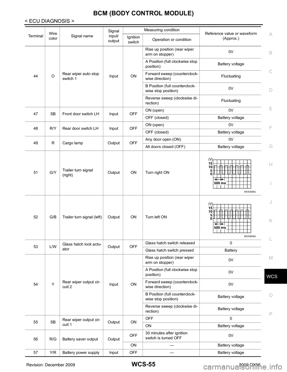
(right) Output ON Turn right ON
52 G/B Trailer turn signal (left) Output ON Turn left ON
53 L/W Glass hatch lock actu-
ator
Output OFFGlass hatch switch released
0
Glass hatch switch pressed Battery
54 Y Rear wiper output cir-
cuit 2 Input ONRise up position (rear wiper
arm on stopper)
0V
A Position (full clockwise stop
position) 0V
Forward sweep (counterclock-
wise direction) 0V
B Position (full counterclock-
wise stop position) Battery voltage
Reverse sweep (clockwise di-
rection) Battery voltage
55 SB Rear wiper output cir-
cuit 1 Output ONOFF
0
ON Battery voltage
56 R/G Battery saver output Output OFF
30 minutes after ignition
switch is turned OFF 0V
ON — Battery voltage
57 Y/R Battery power supply Input OFF —Battery voltage
Te r m i n a l
Wire
color Signal name Signal
input/
output Measuring condition
Reference value or waveform
(Approx.)
Ignition
switch Operation or condition
SKIA3009J
SKIA3009J
Revision: December 20092009 QX56
Page 4132 of 4171

BCM (BODY CONTROL MODULE)WW-45
< ECU DIAGNOSIS >
C
DE
F
G H
I
J
K
M A
B
WW
N
O P
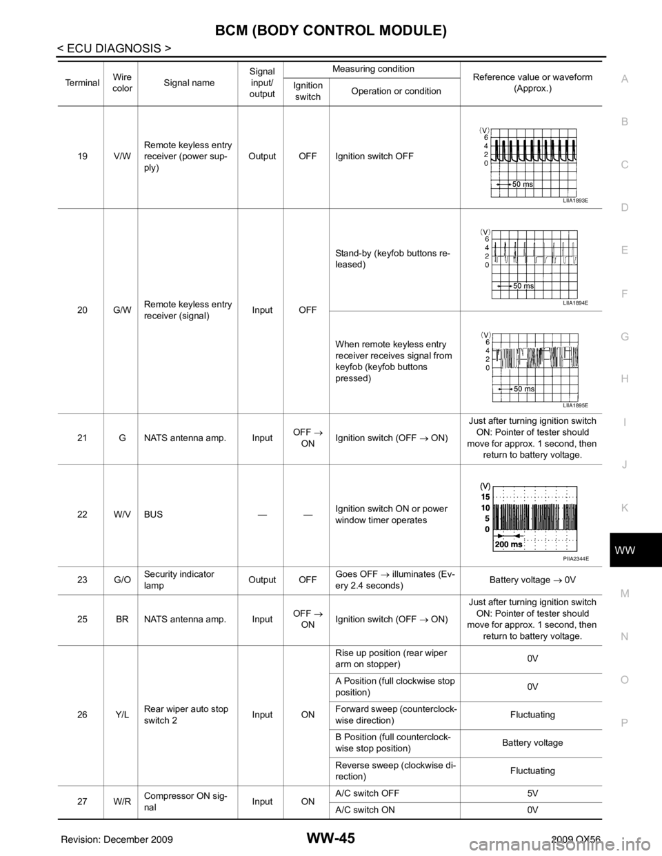
19 V/W Remote keyless entry
receiver (power sup-
ply) Output OFF Ignition switch OFF
20 G/W Remote keyless entry
receiver (signal) Input OFFStand-by (keyfob buttons re-
leased)
When remote keyless entry
receiver receives signal from
keyfob (keyfob buttons
pressed)
21 G NATS antenna amp. Input OFF
→
ON Ignition switch (OFF → ON) Just after turning ignition switch
ON: Pointer of tester should
move for approx. 1 second, then return to battery voltage.
22 W/V BUS — —Ignition switch ON or power
window timer operates
23 G/O Security indicator
lamp Output OFF
Goes OFF
→ illuminates (Ev-
ery 2.4 seconds) Battery voltage
→ 0V
25 BR NATS antenna amp. Input OFF
→
ON Ignition switch (OFF → ON) Just after turning ignition switch
ON: Pointer of tester should
move for approx. 1 second, then return to battery voltage.
26 Y/L Rear wiper auto stop
switch 2 Input ONRise up position (rear wiper
arm on stopper)
0V
A Position (full clockwise stop
position) 0V
Forward sweep (counterclock-
wise direction) Fluctuating
B Position (full counterclock-
wise stop position) Battery voltage
Reverse sweep (clockwise di-
rection) Fluctuating
27 W/R Compressor ON sig-
nal Input ONA/C switch OFF
5V
A/C switch ON 0V
Te r m i n a l
Wire
color Signal name Signal
input/
output Measuring condition
Reference value or waveform
(Approx.)
Ignition
switch Operation or condition
LIIA1893E
LIIA1894E
LIIA1895E
PIIA2344E
Revision: December 20092009 QX56
Page 4134 of 4171

BCM (BODY CONTROL MODULE)WW-47
< ECU DIAGNOSIS >
C
DE
F
G H
I
J
K
M A
B
WW
N
O P
44 O Rear wiper auto stop
switch 1 Input ONRise up position (rear wiper
arm on stopper)
0V
A Position (full clockwise stop
position) Battery voltage
Forward sweep (counterclock-
wise direction) Fluctuating
B Position (full counterclock-
wise stop position) 0V
Reverse sweep (clockwise di-
rection) Fluctuating
47 SB Front door switch LH Input OFF ON (open)
0V
OFF (closed) Battery voltage
48 R/Y Rear door switch LH Input OFF ON (open)
0V
OFF (closed) Battery voltage
49 R Cargo lamp Output OFFAny door open (ON)
0V
All doors closed (OFF) Battery voltage
51 G/Y Trailer turn signal
(right) Output ON Turn right ON
52 G/B Trailer turn signal (left) Output ON Turn left ON
53 L/W Glass hatch lock actu-
ator
Output OFFGlass hatch switch released
0
Glass hatch switch pressed Battery
54 Y Rear wiper output cir-
cuit 2 Input ONRise up position (rear wiper
arm on stopper)
0V
A Position (full clockwise stop
position) 0V
Forward sweep (counterclock-
wise direction) 0V
B Position (full counterclock-
wise stop position) Battery voltage
Reverse sweep (clockwise di-
rection) Battery voltage
55 SB Rear wiper output cir-
cuit 1 Output ONOFF
0
ON Battery voltage
56 R/G Battery saver output Output OFF
30 minutes after ignition
switch is turned OFF 0V
ON — Battery voltage
57 Y/R Battery power supply Input OFF —Battery voltage
Te r m i n a l
Wire
color Signal name Signal
input/
output Measuring condition
Reference value or waveform
(Approx.)
Ignition
switch Operation or condition
SKIA3009J
SKIA3009J
Revision: December 20092009 QX56