2009 INFINITI QX56 oil pressure
[x] Cancel search: oil pressurePage 2673 of 4171
LU-18
< SERVICE DATA AND SPECIFICATIONS (SDS)
SERVICE DATA AND SPECIFICATIONS (SDS)
SERVICE DATA AND SPECIFICATIONS (SDS)
SERVICE DATA AND SPECIFICATIONS (SDS)
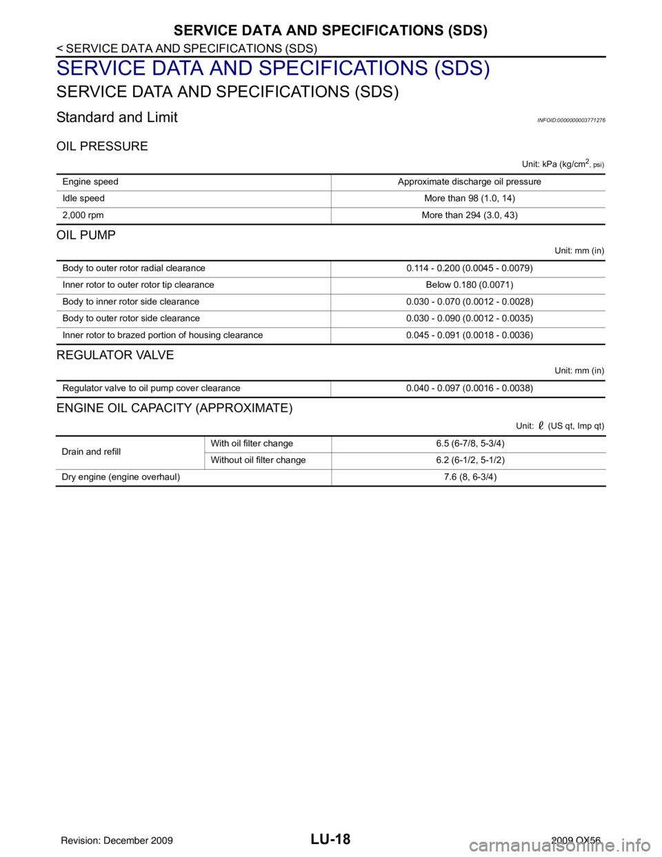
Standard and LimitINFOID:0000000003771276
OIL PRESSURE
Unit: kPa (kg/cm2, psi)
OIL PUMP
Unit: mm (in)
REGULATOR VALVE
Unit: mm (in)
ENGINE OIL CAPACITY (APPROXIMATE)
Unit: (US qt, Imp qt)
Engine speed Approximate discharge oil pressure
Idle speed More than 98 (1.0, 14)
2,000 rpm More than 294 (3.0, 43)
Body to outer rotor radial clearance0.114 - 0.200 (0.0045 - 0.0079)
Inner rotor to outer rotor tip clearance Below 0.180 (0.0071)
Body to inner rotor side clearance 0.030 - 0.070 (0.0012 - 0.0028)
Body to outer rotor side clearance 0.030 - 0.090 (0.0012 - 0.0035)
Inner rotor to brazed portion of housing clearance 0.045 - 0.091 (0.0018 - 0.0036)
Regulator valve to oil pump cover clearance 0.040 - 0.097 (0.0016 - 0.0038)
Drain and refillWith oil filter change 6.5 (6-7/8, 5-3/4)
Without oil filter change
6.2 (6-1/2, 5-1/2)
Dry engine (engine overhaul) 7.6 (8, 6-3/4)
Revision: December 20092009 QX56
Page 2677 of 4171
MA-4
< PREPARATION >
PREPARATION
PREPARATION
PREPARATION
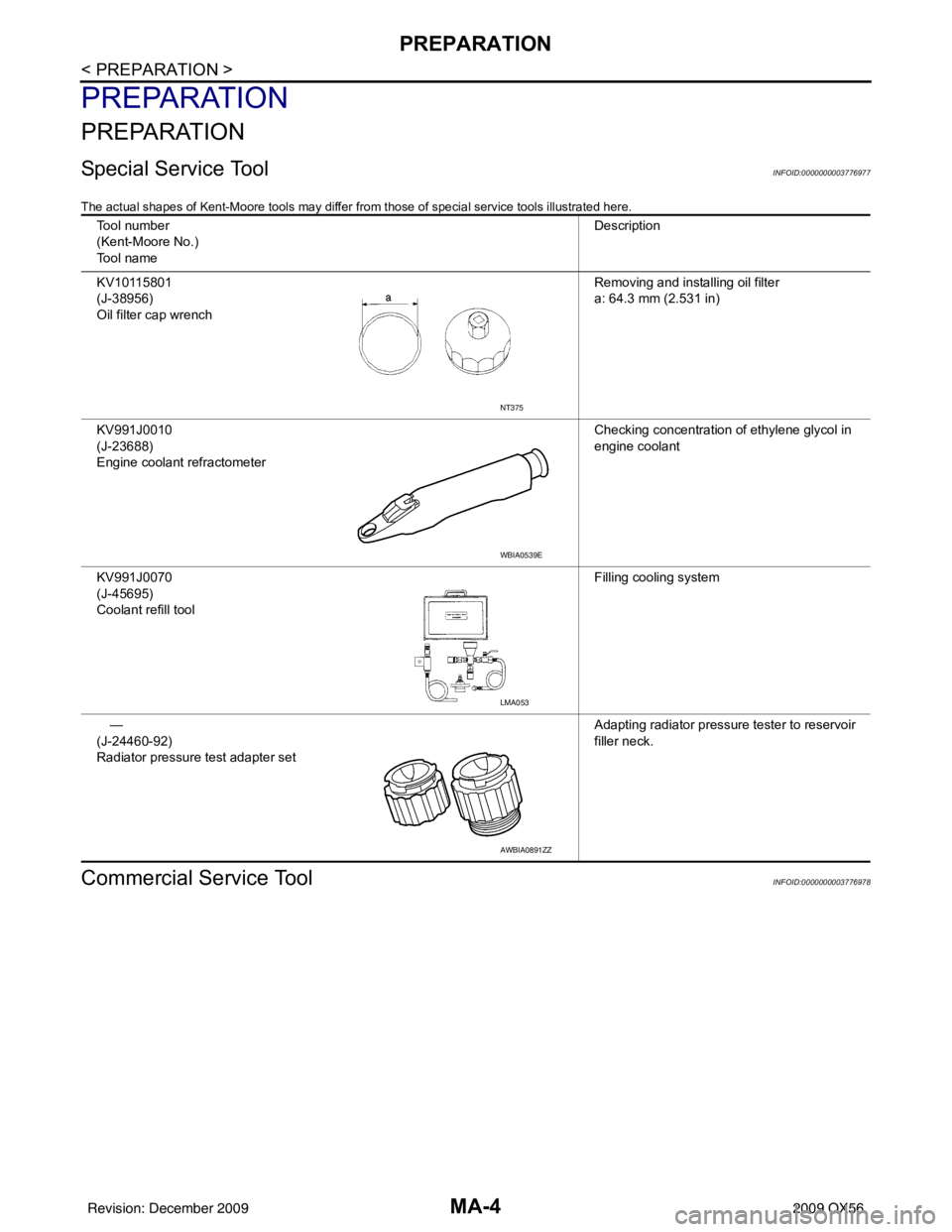
Special Service ToolINFOID:0000000003776977
The actual shapes of Kent-Moore tools may differ from those of special service tools illustrated here.
Commercial Service ToolINFOID:0000000003776978
Tool number
(Kent-Moore No.)
Tool name Description
KV10115801
(J-38956)
Oil filter cap wrench Removing and installing oil filter
a: 64.3 mm (2.531 in)
KV991J0010
(J-23688)
Engine coolant refractometer Checking concentration of ethylene glycol in
engine coolant
KV991J0070
(J-45695)
Coolant refill tool Filling cooling system
—
(J-24460-92)
Radiator pressure test adapter set Adapting radiator pressure tester to reservoir
filler neck.
NT375
WBIA0539E
LMA053
AWBIA0891ZZ
Revision: December 20092009 QX56
Page 2693 of 4171
MA-20
< ON-VEHICLE MAINTENANCE >
ENGINE MAINTENANCE
REMOVAL
1. Disconnect the harness connector from the ignition coil.
2. Remove ignition coil.CAUTION:
Do not shock ig nition coil.
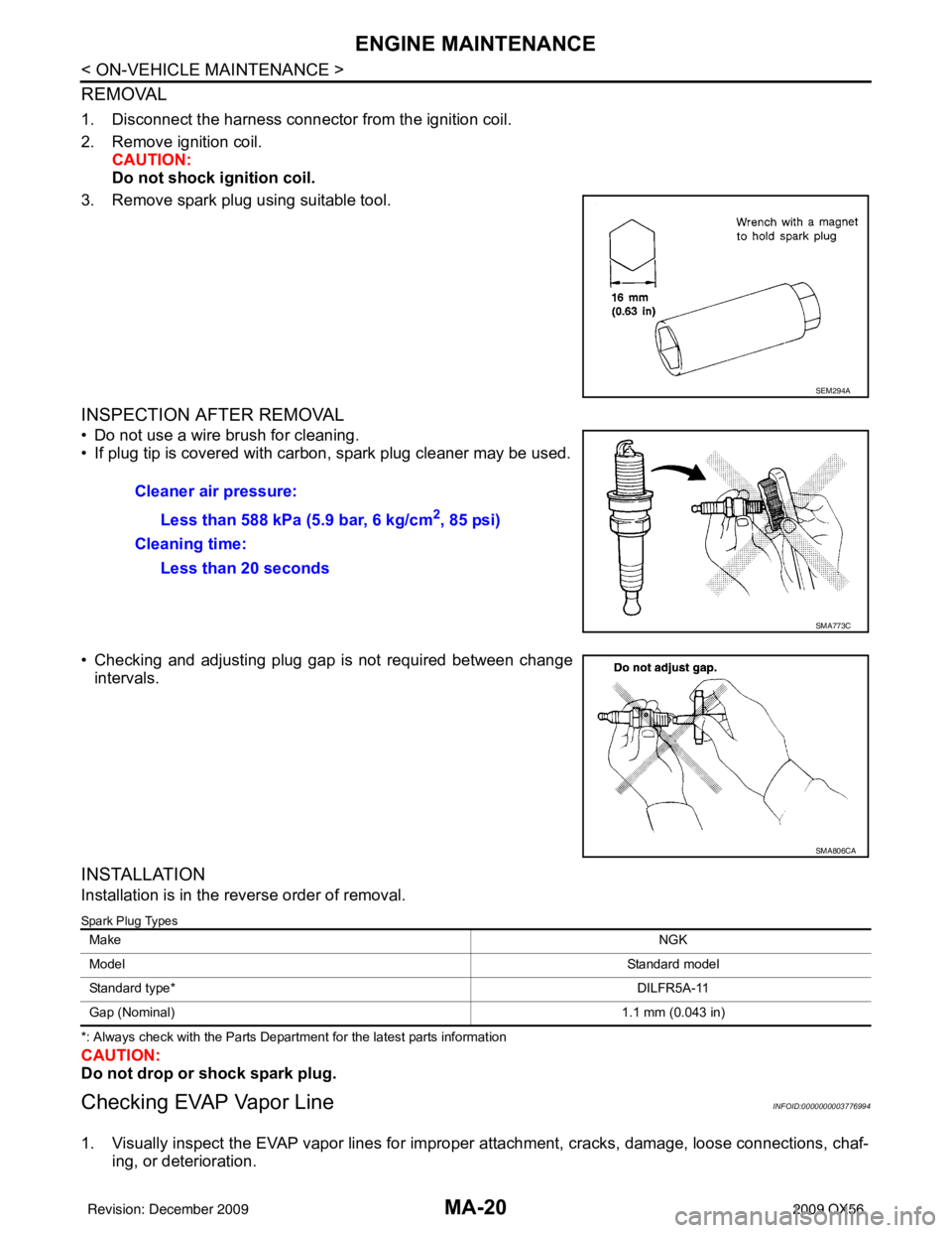
3. Remove spark plug using suitable tool.
INSPECTION AFTER REMOVAL
• Do not use a wire brush for cleaning.
• If plug tip is covered with carbon, spark plug cleaner may be used.
• Checking and adjusting plug gap is not required between change intervals.
INSTALLATION
Installation is in the reverse order of removal.
Spark Plug Types
*: Always check with the Parts Department for the latest parts information
CAUTION:
Do not drop or shock spark plug.
Checking EVAP Vapor LineINFOID:0000000003776994
1. Visually inspect the EVAP vapor lines for improper attachment, cracks, damage, loose connections, chaf-
ing, or deterioration.
SEM294A
Cleaner air pressure:
Less than 588 kPa (5.9 bar, 6 kg/cm
2, 85 psi)
Cleaning time: Less than 20 seconds
SMA773C
SMA806CA
Make NGK
Model Standard model
Standard type* DILFR5A-11
Gap (Nominal) 1.1 mm (0.043 in)
Revision: December 20092009 QX56
Page 2723 of 4171
MWI
MWI-1
DRIVER INFORMATION & MULTIMEDIA
C
DE
F
G H
I
J
K L
M B
SECTION MWI
A
O P
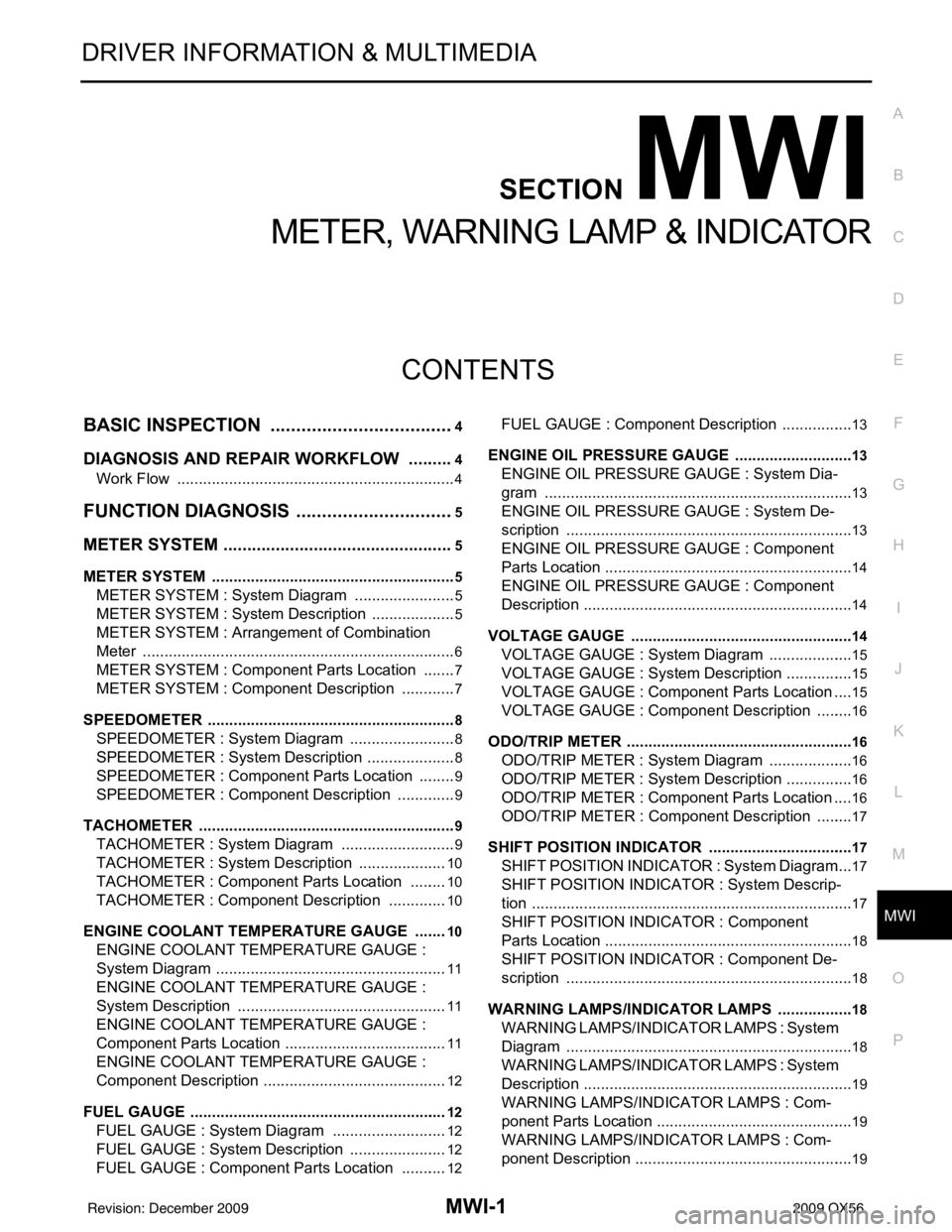
CONTENTS
METER, WARNING LAMP & INDICATOR
BASIC INSPECTION ....... .............................4
DIAGNOSIS AND REPAIR WORKFLOW ..... .....4
Work Flow ........................................................... ......4
FUNCTION DIAGNOSIS ...............................5
METER SYSTEM ............................................ .....5
METER SYSTEM .........................................................5
METER SYSTEM : System Diagram ........................5
METER SYSTEM : System Description ....................5
METER SYSTEM : Arrangem ent of Combination
Meter ................................................................... ......
6
METER SYSTEM : Component Parts Location ........7
METER SYSTEM : Component Description ....... ......7
SPEEDOMETER ..........................................................8
SPEEDOMETER : System Diagram ................... ......8
SPEEDOMETER : System Description .....................8
SPEEDOMETER : Component Parts Location .........9
SPEEDOMETER : Component Description ........ ......9
TACHOMETER ...................................................... ......9
TACHOMETER : System Diagram ...........................9
TACHOMETER : System De scription .....................10
TACHOMETER : Component Parts Location ..... ....10
TACHOMETER : Component Description ..............10
ENGINE COOLANT TEMPERATURE GAUGE .... ....10
ENGINE COOLANT TEMPERATURE GAUGE :
System Diagram ......................................................
11
ENGINE COOLANT TEMPERATURE GAUGE :
System Description .................................................
11
ENGINE COOLANT TEMPERATURE GAUGE :
Component Parts Location ......................................
11
ENGINE COOLANT TEMPERATURE GAUGE :
Component Description ...........................................
12
FUEL GAUGE ........................................................ ....12
FUEL GAUGE : System Diagram ...........................12
FUEL GAUGE : System Description .......................12
FUEL GAUGE : Component Parts Location ...........12
FUEL GAUGE : Component Description ............. ....13
ENGINE OIL PRESSURE GAUGE ............................13
ENGINE OIL PRESSURE GAUGE : System Dia-
gram .................................................................... ....
13
ENGINE OIL PRESSURE GAUGE : System De-
scription ...................................................................
13
ENGINE OIL PRESSURE GAUGE : Component
Parts Location ..........................................................
14
ENGINE OIL PRESSURE GAUGE : Component
Description ...............................................................
14
VOLTAGE GAUGE ................................................ ....14
VOLTAGE GAUGE : System Diagram ....................15
VOLTAGE GAUGE : System Description ................15
VOLTAGE GAUGE : Component Parts Location ....15
VOLTAGE GAUGE : Component Description .........16
ODO/TRIP METER ................................................. ....16
ODO/TRIP METER : System Diagram ....................16
ODO/TRIP METER : System Description ................16
ODO/TRIP METER : Component Parts Location ....16
ODO/TRIP METER : Component Description .........17
SHIFT POSITION INDICATOR .............................. ....17
SHIFT POSITION INDICATOR : System Diagram ....17
SHIFT POSITION INDICATOR : System Descrip-
tion ...........................................................................
17
SHIFT POSITION INDICATOR : Component
Parts Location ..........................................................
18
SHIFT POSITION INDICATOR : Component De-
scription ............................................................... ....
18
WARNING LAMPS/INDICATOR LAMPS .............. ....18
WARNING LAMPS/INDICATOR LAMPS : System
Diagram ............................................................... ....
18
WARNING LAMPS/INDICATOR LAMPS : System
Description ........................................................... ....
19
WARNING LAMPS/INDICATOR LAMPS : Com-
ponent Parts Location ..............................................
19
WARNING LAMPS/INDICATOR LAMPS : Com-
ponent Description ...................................................
19
Revision: December 20092009 QX56
Page 2724 of 4171

MWI-2
INFORMATION DISPLAY .........................................19
INFORMATION DISPLAY : System Diagram .........20
INFORMATION DISPLAY : System Description ....20
INFORMATION DISPLAY : Component Parts Lo-
cation ................................................................... ...
21
INFORMATION DISPLAY : Component Descrip-
tion ....................................................................... ...
21
COMPASS .........................................................22
Description (Early Production) ............................. ...22
DIAGNOSIS SYSTEM (METER) .......................24
Diagnosis Description .......................................... ...24
CONSULT-III Function (METER/M&A) ................ ...25
COMPONENT DIAGNOSIS ........................28
DTC U1000 CAN COMMUNICATION ............ ...28
DTC Logic ............................................................ ...28
Diagnosis Procedure .............................................28
DTC B2205 VEHICLE SPEED CIRCUIT ...........29
Description ........................................................... ...29
DTC Logic ...............................................................29
Diagnosis Procedure .............................................29
POWER SUPPLY AND GROUND CIRCUIT .....30
COMBINATION METER ........................................ ...30
COMBINATION METER : Diagnosis Procedure ....30
BCM (BODY CONTROL MODULE) ...................... ...30
BCM (BODY CONTROL MODULE) : Diagnosis
Procedure ...............................................................
31
IPDM E/R (INTELLIGENT POWER DISTRIBU-
TION MODULE ENGINE ROOM) .......................... ...
31
IPDM E/R (INTELLIGENT POWER DISTRIBU-
TION MODULE ENGINE ROOM) : Diagnosis Pro-
cedure .....................................................................
31
FUEL LEVEL SENSOR SIGNAL CIRCUIT .......33
Description ........................................................... ...33
Component Function Check ...................................33
Diagnosis Procedure .............................................33
Component Inspection ............................................34
OIL PRESSURE SWITCH SIGNAL CIRCUIT ...35
Description ..............................................................35
Component Function Check ...................................35
Diagnosis Procedure ..............................................35
Component Inspection ............................................35
PARKING BRAKE SWITCH SIGNAL CIR-
CUIT ...................................................................
36
Description ........................................................... ...36
Component Function Check ...................................36
Diagnosis Procedure ..............................................36
Component Inspection ............................................36
WASHER LEVEL SWITCH SIGNAL CIRCUIT ...37
Description ........................................................... ...37
Diagnosis Procedure ............................................ ...37
Component Inspection ............................................37
COMPASS .........................................................38
Wiring Diagram (Early Production) ...................... ...38
CLOCK ..............................................................40
Wiring Diagram .................................................... ...40
ECU DIAGNOSIS .......................................42
COMBINATION METER ................................. ...42
Reference Value .................................................. ...42
Wiring Diagram .......................................................44
Fail Safe ..................................................................61
DTC Index ...............................................................62
BCM (BODY CONTROL MODULE) ..................64
Reference Value .................................................. ...64
Terminal Layout ......................................................66
Physical Values .......................................................66
Wiring Diagram .......................................................72
Fail Safe .................................................................76
DTC Inspection Priority Chart ...............................77
DTC Index ..............................................................77
IPDM E/R (INTELLIGENT POWER DISTRI-
BUTION MODULE ENGINE ROOM) .................
79
Reference Value .................................................. ...79
Terminal Layout ......................................................81
Physical Values .......................................................81
Wiring Diagram .......................................................86
Fail Safe .................................................................89
DTC Index ..............................................................91
SYMPTOM DIAGNOSIS ............................92
THE FUEL GAUGE POINTER DOES NOT
MOVE .............................................................. ...
92
Description ........................................................... ...92
Diagnosis Procedure ...............................................92
THE FUEL GAUGE POINTER DOES NOT
MOVE TO "F" WHEN REFUELING ..................
93
Description ........................................................... ...93
Diagnosis Procedure ...............................................93
THE OIL PRESSURE WARNING LAMP
DOES NOT TURN ON .................................... ...
94
Description ........................................................... ...94
Diagnosis Procedure ...............................................94
THE OIL PRESSURE WARNING LAMP
DOES NOT TURN OFF .................................. ...
95
Description ........................................................... ...95
Diagnosis Procedure ...............................................95
THE PARKING BRAKE RELEASE WARNING
CONTINUES DISPLAYING, OR DOES NOT
DISPLAY ............................................................
96
Description ........................................................... ...96
Revision: December 20092009 QX56
Page 2729 of 4171
MWI
METER SYSTEMMWI-7
< FUNCTION DIAGNOSIS >
C
DE
F
G H
I
J
K L
M B A
O P
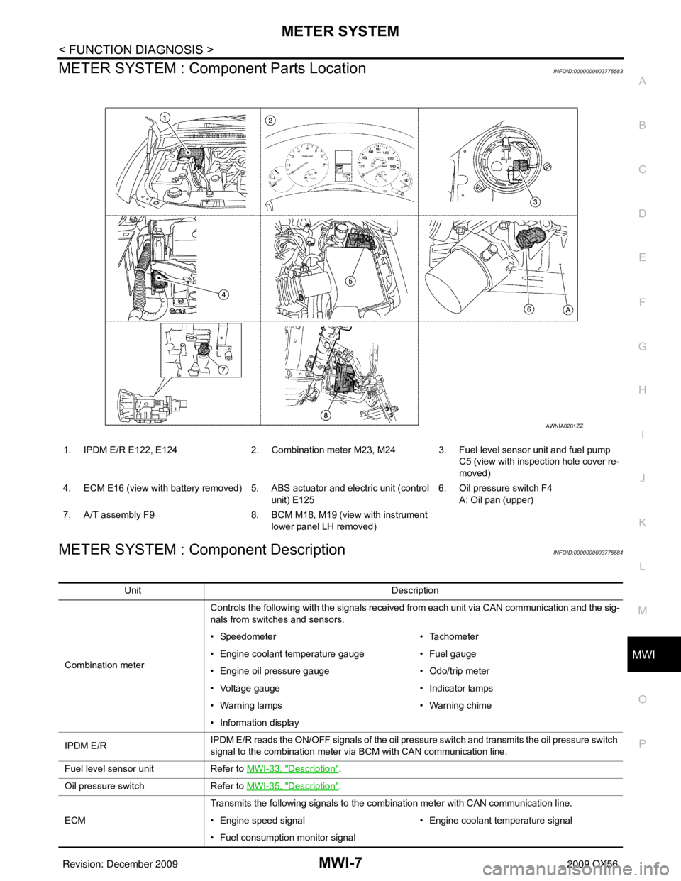
METER SYSTEM : Com ponent Parts LocationINFOID:0000000003776583
METER SYSTEM : Component DescriptionINFOID:0000000003776584
1. IPDM E/R E122, E124 2. Combination meter M23, M24 3. Fuel level sensor unit and fuel pump
C5 (view with inspection hole cover re-
moved)
4. ECM E16 (view with battery removed) 5. ABS actuator and electric unit (control unit) E1256. Oil pressure switch F4
A: Oil pan (upper)
7. A/T assembly F9 8. BCM M18, M19 (view with instrument
lower panel LH removed)
AWNIA0201ZZ
Unit Description
Combination meter Controls the following with the signals received from each unit via CAN communication and the sig-
nals from switches and sensors.
• Speedometer
• Tachometer
• Engine coolant temperature gauge • Fuel gauge
• Engine oil pressure gauge • Odo/trip meter
• Voltage gauge • Indicator lamps
• Warning lamps • Warning chime
• Information display
IPDM E/R IPDM E/R reads the ON/OFF signals of the oil pressure switch and transmits the oil pressure switch
signal to the combination meter via BCM with CAN communication line.
Fuel level sensor unit Refer to MWI-33, "
Description".
Oil pressure switch Refer to MWI-35, "
Description".
ECM Transmits the following signals to the combination meter with CAN communication line.
• Engine speed signal
• Engine coolant temperature signal
• Fuel consumption monitor signal
Revision: December 20092009 QX56
Page 2731 of 4171
MWI
METER SYSTEMMWI-9
< FUNCTION DIAGNOSIS >
C
DE
F
G H
I
J
K L
M B A
O P
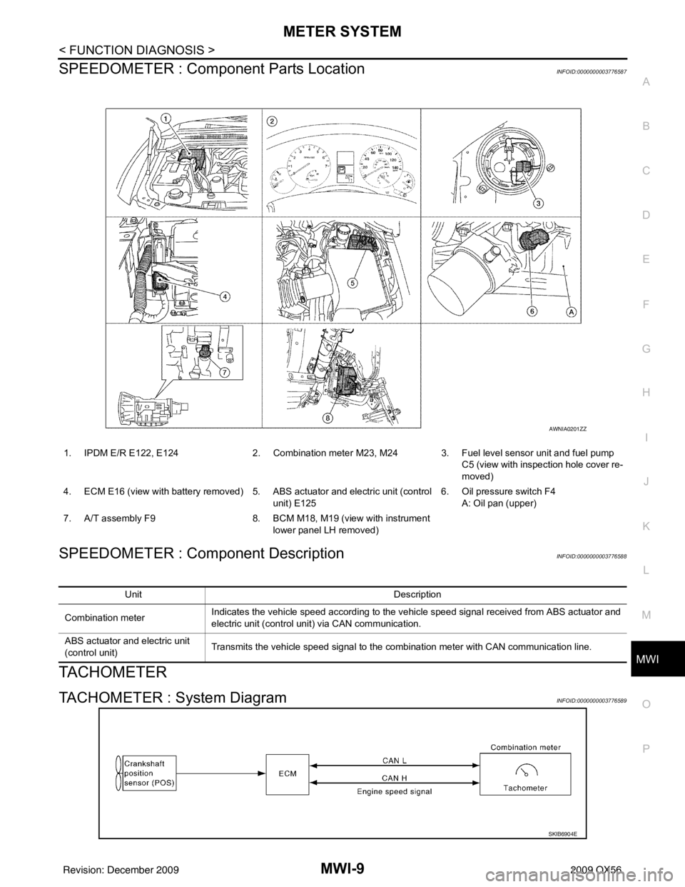
SPEEDOMETER : Compone nt Parts LocationINFOID:0000000003776587
SPEEDOMETER : Component DescriptionINFOID:0000000003776588
TACHOMETER
TACHOMETER : System DiagramINFOID:0000000003776589
1. IPDM E/R E122, E124 2. Combination meter M23, M24 3. Fuel level sensor unit and fuel pump
C5 (view with inspection hole cover re-
moved)
4. ECM E16 (view with battery removed) 5. ABS actuator and electric unit (control unit) E1256. Oil pressure switch F4
A: Oil pan (upper)
7. A/T assembly F9 8. BCM M18, M19 (view with instrument
lower panel LH removed)
AWNIA0201ZZ
Unit Description
Combination meter Indicates the vehicle speed according to the vehicle speed signal received from ABS actuator and
electric unit (control unit) via CAN communication.
ABS actuator and electric unit
(control unit) Transmits the vehicle speed signal to the combination meter with CAN communication line.
SKIB6904E
Revision: December 20092009 QX56
Page 2732 of 4171

MWI-10
< FUNCTION DIAGNOSIS >
METER SYSTEM
TACHOMETER : System Description
INFOID:0000000003776590
The tachometer indicates engine speed in revolutions per minute (rpm).
The ECM provides an engine speed signal to the co mbination meter via CAN communication lines.
TACHOMETER : Component Parts LocationINFOID:0000000003776591
TACHOMETER : Component DescriptionINFOID:0000000003776592
ENGINE COOLANT TEMPERATURE GAUGE
1. IPDM E/R E122, E1242. Combination meter M23, M24 3. Fuel level sensor unit and fuel pump
C5 (view with inspection hole cover re-
moved)
4. ECM E16 (view with battery removed) 5. ABS actuator and electric unit (control
unit) E125 6. Oil pressure switch F4
A: Oil pan (upper)
7. A/T assembly F9 8. BCM M18, M19 (view with instrument
lower panel LH removed)
AWNIA0201ZZ
Unit Description
Combination meter Indicates the engine speed in RPM according to the engine speed signal received from ECM via
CAN communication.
ECM Transmits the engine speed signal to the combination meter with CAN communication line.
Revision: December 20092009 QX56