2009 INFINITI QX56 oil pressure
[x] Cancel search: oil pressurePage 2850 of 4171
![INFINITI QX56 2009 Factory Service Manual PCS
DIAGNOSIS SYSTEM (IPDM E/R)PCS-13
< FUNCTION DIAGNOSIS > [IPDM E/R]
C
D
E
F
G H
I
J
K L
B A
O P
N
Concept of auto active test
• IPDM E/R starts the auto active test with the door
switch signals INFINITI QX56 2009 Factory Service Manual PCS
DIAGNOSIS SYSTEM (IPDM E/R)PCS-13
< FUNCTION DIAGNOSIS > [IPDM E/R]
C
D
E
F
G H
I
J
K L
B A
O P
N
Concept of auto active test
• IPDM E/R starts the auto active test with the door
switch signals](/manual-img/42/57031/w960_57031-2849.png)
PCS
DIAGNOSIS SYSTEM (IPDM E/R)PCS-13
< FUNCTION DIAGNOSIS > [IPDM E/R]
C
D
E
F
G H
I
J
K L
B A
O P
N
Concept of auto active test
• IPDM E/R starts the auto active test with the door
switch signals transmitted by BCM via CAN communica-
tion. Therefore, the CAN communication line between IPDM E/R and BCM is considered normal if the auto
active test starts successfully.
• The auto active test facilitates troubleshooting if any systems controlled by IPDM E/R cannot be operated.
Diagnosis chart in auto active test mode
3 Tail, license and parking lamps 10 seconds
4 Front fog lamps 10 seconds
5 Headlamps LO for 10 seconds → HI on-off for 5 seconds
6 A/C compressor (magnet clutch) ON ⇔ OFF 5 times
7 Cooling fan 10 seconds
Operation
sequence Inspection Location
Operation
WKIA5163E
SymptomInspection contentsPossible cause
Oil pressure low warning indicator does not operate Perform auto active test.
Does the oil pressure low
warning indicator operate?YES
• IPDM E/R signal input cir-
cuit
• ECM signal input circuit
• CAN communication signal between ECM and combi-
nation meter
NO • CAN communication signal
between IPDM E/R, BCM
and combination meter
Oil pressure gauge does not operate Perform auto active test.
Does the oil pressure gauge
operate?YES IPDM E/R signal input circuit
NO • CAN communication signal
between IPDM E/R, BCM
and combination meter
Rear window defogger does not operate Perform auto active test.
Does the rear window defog-
ger operate?YES BCM signal input circuit
NO • Harness or connector be-
tween A/C and AV switch
assembly and AV control
unit
• CAN communication signal between BCM and IPDM E/
R
Revision: December 20092009 QX56
Page 2852 of 4171
![INFINITI QX56 2009 Factory Service Manual PCS
DIAGNOSIS SYSTEM (IPDM E/R)PCS-15
< FUNCTION DIAGNOSIS > [IPDM E/R]
C
D
E
F
G H
I
J
K L
B A
O P
N
ACTIVE TEST
Te s t i t e m
Monitor Item
[Unit] MAIN SIG-
NALS Description
MOTOR FAN REQ
[1/2/3/4] INFINITI QX56 2009 Factory Service Manual PCS
DIAGNOSIS SYSTEM (IPDM E/R)PCS-15
< FUNCTION DIAGNOSIS > [IPDM E/R]
C
D
E
F
G H
I
J
K L
B A
O P
N
ACTIVE TEST
Te s t i t e m
Monitor Item
[Unit] MAIN SIG-
NALS Description
MOTOR FAN REQ
[1/2/3/4]](/manual-img/42/57031/w960_57031-2851.png)
PCS
DIAGNOSIS SYSTEM (IPDM E/R)PCS-15
< FUNCTION DIAGNOSIS > [IPDM E/R]
C
D
E
F
G H
I
J
K L
B A
O P
N
ACTIVE TEST
Te s t i t e m
Monitor Item
[Unit] MAIN SIG-
NALS Description
MOTOR FAN REQ
[1/2/3/4] ×Displays the status of the cooling fan speed request signal received from ECM via
CAN communication.
A/C COMP REQ
[OFF/ON] ×Displays the status of the A/C request signal received from AV control unit via
CAN communication.
TAIL&CLR REQ
[OFF/ON] ×
Displays the status of the position light request signal received from BCM via CAN
communication.
HL LO REQ
[OFF/ON] ×Displays the status of the low beam request signal received from BCM via CAN
communication.
HL HI REQ
[OFF/ON] ×Displays the status of the high beam request signal received from BCM via CAN
communication.
FR FOG REQ
[OFF/ON] ×
Displays the status of the front fog lamp request signal received from BCM via
CAN communication.
FR WIP REQ
[STOP/1LOW/LOW/HI] ×Displays the status of the front wiper request signal received from BCM via CAN
communication.
WIP AUTO STOP
[STOP P/ACT P] ×
Displays the status of the front wiper auto stop signal judged by IPDM E/R.
WIP PROT
[OFF/Block] ×
Displays the status of the front wiper fail-safe operation judged by IPDM E/R.
ST RLY REQ
[OFF/ON] Displays the status of the starter request signal received from ECM via CAN com-
munication.
IGN RLY
[OFF/ON] ×
Displays the status of the ignition relay judged by IPDM E/R.
RR DEF REQ
[OFF/ON] ×
Displays the status of the rear defogger request signal received from AV control
unit via CAN communication.
OIL P SW
[OPEN/CLOSE] Displays the status of the oil pressure switch judged by IPDM E/R.
DTRL REQ
[OFF] Displays the status of the daytime light request signal received from BCM via CAN
communication.
HOOD SW
[OPEN/CLOSE] Displays the status of the hood switch judged by IPDM E/R.
THFT HRN REQ
[OFF/ON] Displays the status of the theft warning horn request signal received from BCM
via CAN communication.
HORN CHIRP
[OFF/ON] Displays the status of the horn reminder signal received from BCM via CAN com-
munication.
Test item
Operation Description
REAR DEFOGGER OFF
OFF
ON Operates rear window defogger relay.
FRONT WIPER OFF
OFF
LO Operates the front wiper relay.
HI Operates the front wiper relay and front wiper high relay.
MOTOR FAN 1O
FF
2O FF
3 Operates the cooling fan relay.
4 Operates the cooling fan relay.
Revision: December 20092009 QX56
Page 2860 of 4171
![INFINITI QX56 2009 Factory Service Manual PCS
IPDM E/R (INTELLIGENT POWER DISTRIBUTION MODULE ENGINE ROOM)
PCS-23
< ECU DIAGNOSIS > [IPDM E/R]
C
D
E
F
G H
I
J
K L
B A
O P
N26 P/L
Headlamp aiming mo-
tors
Output —Lighting
switch 2nd
positi INFINITI QX56 2009 Factory Service Manual PCS
IPDM E/R (INTELLIGENT POWER DISTRIBUTION MODULE ENGINE ROOM)
PCS-23
< ECU DIAGNOSIS > [IPDM E/R]
C
D
E
F
G H
I
J
K L
B A
O P
N26 P/L
Headlamp aiming mo-
tors
Output —Lighting
switch 2nd
positi](/manual-img/42/57031/w960_57031-2859.png)
PCS
IPDM E/R (INTELLIGENT POWER DISTRIBUTION MODULE ENGINE ROOM)
PCS-23
< ECU DIAGNOSIS > [IPDM E/R]
C
D
E
F
G H
I
J
K L
B A
O P
N26 P/L
Headlamp aiming mo-
tors
Output —Lighting
switch 2nd
position or
AUTO, head-
lamp aiming
switch in po-
sition OFF
0V
ON Battery voltage
27 W/B Fuse 38
(With trailer tow)
Output —Ignition switch ON or START
Battery voltage
Ignition switch OFF or ACC 0V
30 W Fuse 53 Output —Ignition switch ON or START
Battery voltage
Ignition switch OFF or ACC 0V
32 L Wiper low speed sig-
nal
OutputON or
START Wiper switch OFF
Battery voltage
LO or INT 0V
35 L/B Wiper high speed sig-
nal
OutputON or
START Wiper switch OFF, LO, INT Battery voltage
HI 0V
37 Y Power generation
command signal Output —Ignition switch ON
6.3 V
40% is set on "Active test,"
"ALTERNATOR DUTY" of
"ENGINE" 3.8 V
40% is set on "Active test,"
"ALTERNATOR DUTY" of
"ENGINE" 1.4 V
38 B Ground Input ——0V
39 L CAN-H — ON— —
40 P CAN-L — ON— —
41 Y/B Hood switch Input —Hood closed OFF
0V
Hood open ON Battery voltage
42 GR Oil pressure switch Input — Engine running
Battery voltage
Engine stopped 0V
Te r m i n a l
Wire
color Signal name Signal
input/
output Measuring condition
Reference value(Approx.)
Igni-
tion
switch Operation or condition
JPMIA0001GB
JPMIA0002GB
JPMIA0003GB
Revision: December 20092009 QX56
Page 2921 of 4171

PG-50
< COMPONENT DIAGNOSIS >
HARNESS
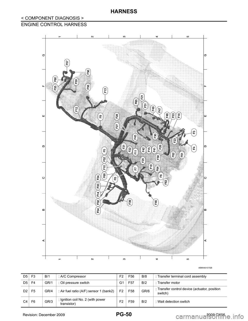
ENGINE CONTROL HARNESS
ABMIA0157GB
D5 F3 B/1 : A/C CompressorF2 F56 B/8 : Transfer terminal cord assembly
D5 F4 GR/1 : Oil pressure switch G1 F57 B/2 : Transfer motor
D2 F5 GR/4 : Air fuel ratio (A/F) sensor 1 (bank2) F2 F58 GR/6 : Transfer control device (actuator, position
switch)
C4 F6 GR/3 : Ignition coil No. 2 (with power
transistor) F2 F59 B/2 : Wait detection switch
Revision: December 20092009 QX56
Page 2922 of 4171

PG
HARNESSPG-51
< COMPONENT DIAGNOSIS >
C
DE
F
G H
I
J
K L
B A
O P
N
C3 F7 GR/3
: Ignition coil No. 4 (with power
transistor) F1 F60 GR/2 : Neutral-4LO switch
C3 F8 GR/3 : Ignition coil No. 6 (with power
transistor)
D5 F61 G/2: Intake valve timing control solenoid valve
(bank 1)
E2 F9 G/10 : A/T assembly D5 F62 B/3: Intake valve timing control position sensor
(bank 1)
C3 F10 — : Engine ground C4 F63 G/2: Intake valve timing control solenoid valve
(bank 2)
D3 F11 B/3 : Crankshaft position sensor (POS) C4 F64 B/3 : Intake valve timing control position sensor
(bank 2)
E1 F12 G/4 : Heated oxygen sensor 2 (bank2) E3 F65 GR/4 : Air fuel ratio (A/F) sensor 1 (bank1)
F2 F13 G/4 : Heated oxygen sensor 2 (bank1) C2 F68 GR/2 : Water valve
B2 F14 W/24 : To E5 Engine control sub-harness
D4 F15 GR/2 : EVAP canister purge volume control
solenoid valve C3 F101 B/6 : To F26
E5 F16 — : Engine ground C3 F102 B/2 : Knock sensor (bank 1)
C4 F18 GR/2 : Fuel injector No. 2 C3 F103 GR/2 : Engine coolant temperature sensor
D4 F20 GR/2 : Fuel injector No. 4 C3 F104 B/2 : Knock sensor (bank 2)
F4 F21 GR/2 : Condenser-1
D3 F22 GR/2 : Fuel injector No. 6
D4 F23 B/3 : Camshaft position sensor (phase)
D4 F26 B/6 : To F101
E3 F27 /1 : Starter motor
E3 F28 GR/1 : Starter motor
D4 F30 GR/2 : Fuel injector No. 1
D3 F31 GR/2 : Fuel injector No. 8
B2 F32 W/16 : To E2
C2 F33 W/16 : To E19
C2 F34 W/2 : To E39
B3 F39 /1 : Fusible link box (battery)
D4 F41 GR/2 : Fuel injector No. 3
D4 F42 GR/2 : Fuel injector No. 5
D3 F45 GR/2 : Fuel injector No. 7
B4 F46 B/3 : Power steering pressure sensor
E4 F47 GR/3 : Ignition coil No. 1 (with power
transistor)
E4 F48 GR/3 : Ignition coil No. 3 (with power
transistor)
E4 F49 GR/3 : Ignition coil No. 5 (with power
transistor)
D4 F50 W/6 : Electric throttle control actuator
E4 F51 GR/3 : Ignition coil No. 7 (with power
transistor)
D2 F52 GR/3 : Ignition coil No. 8 (with power
transistor)
E5 F53 B/6 : Mass air flow sensor
B2 F54 B/81 : ECM
F1 F55 B/2 : ATP switch
Revision: December 20092009 QX56
Page 3160 of 4171

RSU-12
< REMOVAL AND INSTALLATION >
REAR SUSPENSION MEMBER
Rear Load Leveling Air Suspension System
REMOVAL
1. If equipped with rear load leveling air suspension system, use CONSULT-III “EXHAUST SOLENOID”
active test to release the air pressure from the rear load leveling air suspension system.
2. If equipped with the rear load leveling air suspension system, disconnect the electrical connectors for the
height sensor and the rear load leveling air suspension compressor assembly.
3. If equipped with the rear load leveling air suspension system, unclip the rubber cover to access the rear
load leveling air suspension compressor assembly.
1. Seat belt latch anchor 2. Stabilizer bar bushing 3. Stabilizer bar clamp
4. Stabilizer bar 5. Connecting rod 6. Front lower link
7. Knuckle 8. Bushing 9. Rear lower link
10. Shock absorber 11. Suspension arm 12. Lower rubber seat
13. Coil spring 14. Upper rubber seat 15. Rear suspension member
16. Spare tire bracket 17. Bound bumper Front
AWEIA0054GB
1. Rear load leveling air suspension
hose, RH 2. Shock absorber, RH 3. Height sensor
4. Rear load leveling air suspension hose, LH 5. Shock absorber, LH 6. Rear load leveling air suspension
compressor assembly (includes the
bracket and rubber cover)
Front
Revision: December 20092009 QX56
Page 3165 of 4171

SUSPENSION ARMRSU-17
< REMOVAL AND INSTALLATION >
C
DF
G H
I
J
K L
M A
B
RSU
N
O P
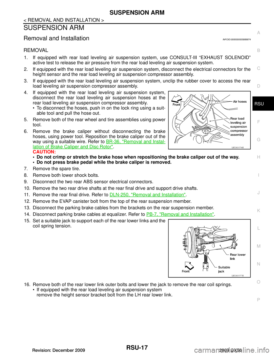
SUSPENSION ARM
Removal and InstallationINFOID:0000000005889874
REMOVAL
1. If equipped with rear load leveling air suspension system, use CONSULT-III “EXHAUST SOLENOID”
active test to release the air pressure from the rear load leveling air suspension system.
2. If equipped with the rear load leveling air suspension system, disconnect the electrical connectors for the
height sensor and the rear load leveling air suspension compressor assembly.
3. If equipped with the rear load leveling air suspension system, unclip the rubber cover to access the rear
load leveling air suspension compressor assembly.
4. If equipped with the rear load leveling air suspension system, disconnect the rear load leveling air suspension hoses at the
rear load leveling air suspension compressor assembly.
To disconnect the hoses, push in on the lock ring using a suit-able tool and pull the hose out.
5. Remove both of the rear wheel and tire assemblies using power tool.
6. Remove the brake caliper without disconnecting the brake hoses, using power tool. Reposition the brake caliper out of the
way using a suitable wire. Refer to BR-36, "Removal and Instal-
lation of Brake Caliper and Disc Rotor".
CAUTION:
Do not crimp or stretch the brake hose when re positioning the brake caliper out of the way.
Do not press brake pedal while the brake caliper is removed.
7. Remove the spare tire.
8. Remove both lower shock bolts.
9. Disconnect the two rear ABS sensor electrical connectors.
10. Remove the two rear drive shafts at t he rear final drive and support drive shafts.
11. Remove the rear final drive. Refer to DLN-250, "Removal and Installation"
.
12. Remove the EVAP canister bolt from the top of the rear suspension member.
13. Disconnect the parking brake cables from t he brackets on the rear suspension member.
14. Disconnect parking brake cables at equalizer. Refer to PB-7, "Removal and Installation"
.
15. Set a suitable jack to support each of the rear lower links and the coil spring tension.
16. Remove both of the rear lower link outer bolts and lower the jack to remove the rear coil springs. If equipped with the rear load leveling air suspension systemremove the height sensor bracket bolt from the LH rear lower link.
LEIA0074E
LEIA0077E
Revision: December 20092009 QX56
Page 3169 of 4171

REAR LOWER LINK & COIL SPRINGRSU-21
< REMOVAL AND INSTALLATION >
C
DF
G H
I
J
K L
M A
B
RSU
N
O P
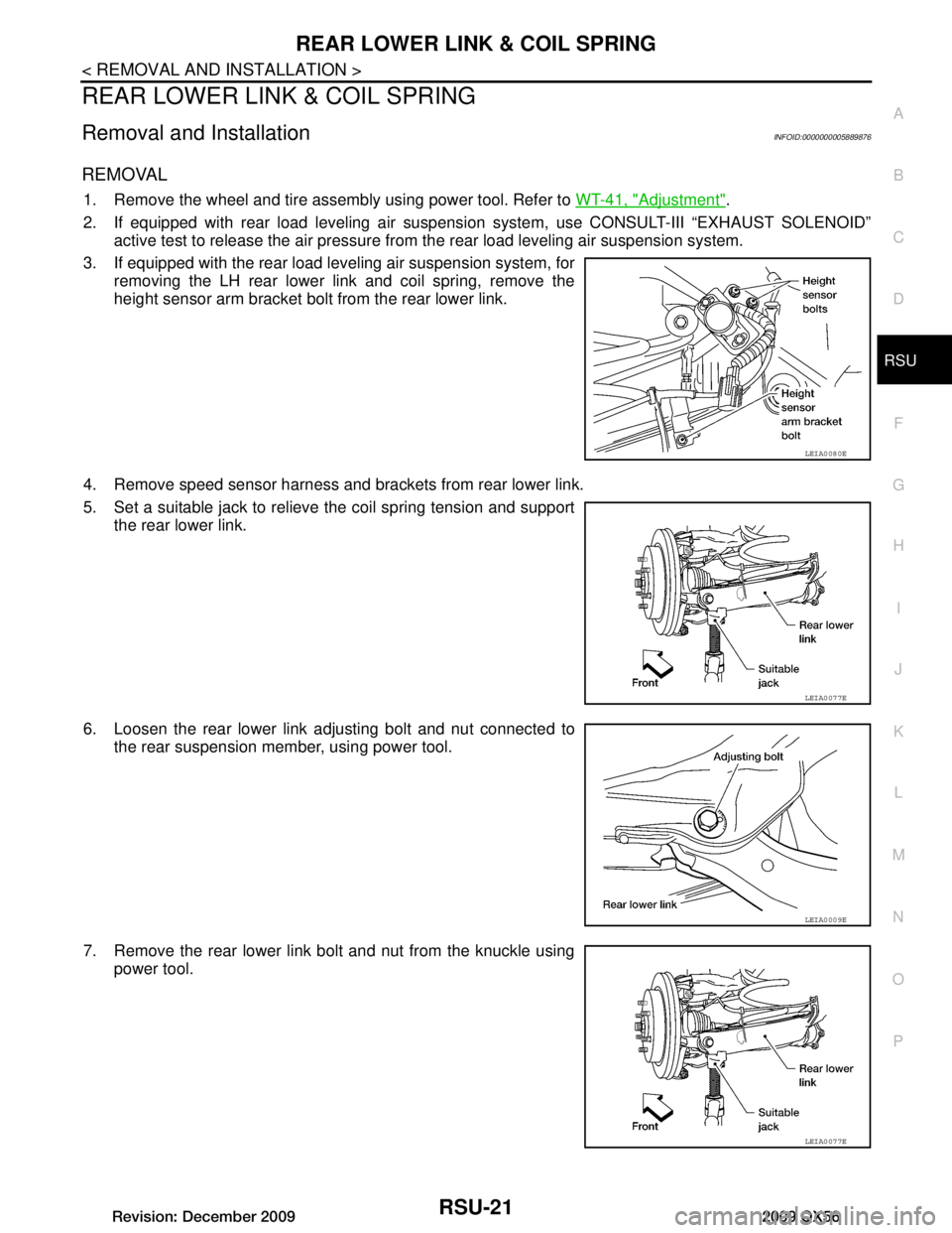
REAR LOWER LINK & COIL SPRING
Removal and InstallationINFOID:0000000005889876
REMOVAL
1. Remove the wheel and tire assembly using power tool. Refer to WT-41, "Adjustment".
2. If equipped with rear load leveling air suspension system, use CONSULT-III “EXHAUST SOLENOID”
active test to release the air pressure from the rear load leveling air suspension system.
3. If equipped with the rear load leveling air suspension system, for removing the LH rear lower link and coil spring, remove the
height sensor arm bracket bolt from the rear lower link.
4. Remove speed sensor harness and brackets from rear lower link.
5. Set a suitable jack to relieve the coil spring tension and support the rear lower link.
6. Loosen the rear lower link adjusting bolt and nut connected to the rear suspension member, using power tool.
7. Remove the rear lower link bolt and nut from the knuckle using power tool.
LEIA0080E
LEIA0077E
LEIA0009E
LEIA0077E
Revision: December 20092009 QX56