2009 Hyundai Accent fuel
[x] Cancel search: fuelPage 212 of 232
6
DO-IT-YOURSELF MAINTENANCE
31
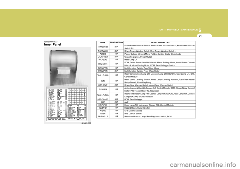
G200E01MC-GAT Inner Panel
G200E01MCFUSE RATING
25A 25A 10A 25A10A 10A15A 25A 10A 10A 20A10A 10A 30A 25A 10A 10A15A 10A 10A CIRCUIT PROTECTED
Driver Power Window Switch, Assist Power Window Switch,Rear Power Window Switch RH Driver Power Window Switch, Rear Power Window Switch LHPower Outside Mirror & Mirror Folding Switch, Digital Clock,Audio Cigarette Lighter, Power Outlet Head Lamp LHECM, Driver Power Outside Mirror & Mirror Folding Motor,Assist Power Outside Mirror & Mirror Folding Motor, PCM, Rear Defogger Switch Multi-function Switch, Rear Wiper MotorMulti-function Switch, Front Wiper Motor Rear Combination Lamp LH, License Lamp LH(3DOOR),Head Lamp LH, DRL Control ModuleHead Lamp Leveling Switch, Head Lamp Leveling Actuator,Fuel Filter Heater Relay(Diesel), Front Fog Relay Driver Seat Warmer Switch, Assist Seat Warmer Switch
Active Interior & Humidity Sensor, A/C Control Module, BCM, Blower Relay, SunroofMotor, PTC Heater Relay #2, #3(Diesel) Rear Combination Lamp RH, License Lamp RH(3DOOR),Head Lamp RH, License Lamp(4DOOR), Shunt ConnectorBCM, Rear Defogger AMP Head Lamp RH, Instrument Cluster, DRL Control Module
Hazard Relay, Hazard Switch SRS Control Module
PAB Cut Off SwitchRear Combination Lamp, Rear Fog Lamp Switch, BCM
P/WDW RH
P/WDW LH AUDIO
C/LIGHTER H/LP (LH)
HTD MIRR
RR WIPER FR WIPER
TAIL LP (LH)
IGN
HTD SEAT BLOWER
TAIL LP (RH) HTD GLASS AMP
H/LP (RH) HAZARD
A/BAG
SNSR
RR FOG LP
FUSE
Page 213 of 232
6 DO-IT-YOURSELF MAINTENANCE
32
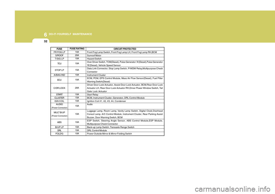
FUSE RATING10A 20A10A 10A 15A 10A10A 20A 10A 15A 10A 15A 10A10A 10A 10A 10A CIRCUIT PROTECTED
Front Fog Lamp Switch, Front Fog Lamp LH, Front Fog Lamp RH,BCM Sunroof Motor Hazard SwitchOver Driver Switch, TCM(Diesel), Pulse Generator 'A'(Diesel),Pulse Generator
'B'(Diesel), Vehicle Speed Sensor
Data Link Connector, Stop Lamp Switch, P/WDW Relay,Multipurpose CheckConnector Instrument Cluster ECM, PCM, EPS Control Module, Mass Air Flow Sensor(Diesel), Fuel FilterWarning Switch(Diesel) Driver Door Lock Actuator, Assist Door Lock Actuator, BCM,Rear Door Lock
Actuator LH, Rear Door Lock Actuator RH,Driver Power Window Switch, TailGate Lock Actuator Start Relay BCM, Instrument Cluster, Generator, DRL Control ModuleIgnition Coil #1, #2, #3, #4, CondenserAudio
Luggage Lamp, Room Lamp, Vanity Lamp Switch, Digital Clock,Overhead Consol Lamp, A/C Control Module, Instrument Cluster, Rear Parking Assist Buzzer, Door Warning Switch, BCM ESP Switch, Steering Angle Sensor, ABS Control Module,ESP Module,Multipurpose Check Connector
Back-up Lamp Switch, Transaxle Range Switch DRL Control ModulePower Outside Mirror & Mirror Folding Switch
FR FOG LP S/ROOF
T/SIG LP
TCU
STOP LP
A/BAG IND ECU
C/DR LOCK START
CLUSTER IGN COIL AUDIO
(Power Connector)
MULT B/UP
(Power Connector)
ABS
B/UP LP DRL
FOLD'G
FUSE
Page 215 of 232
7EMISSION CONTROL SYSTEMS
2EMISSION CONTROL SYS- TEM
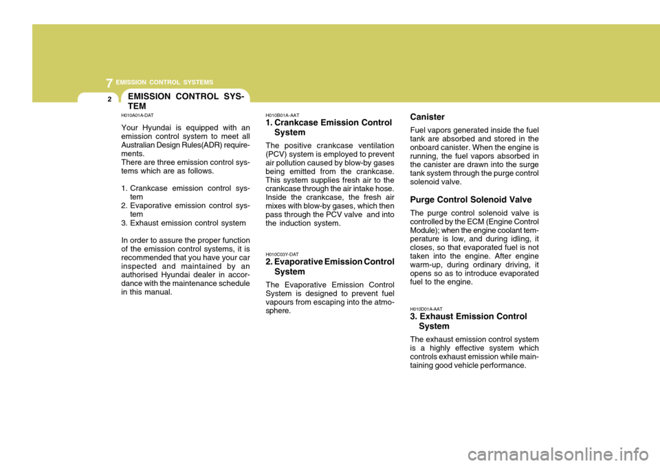
H010A01A-DAT Your Hyundai is equipped with an
emission control system to meet all Australian Design Rules(ADR) require- ments.
There are three emission control sys-
tems which are as follows.
1. Crankcase emission control sys-
tem
2. Evaporative emission control sys-
tem
3. Exhaust emission control system
In order to assure the proper function
of the emission control systems, it is recommended that you have your carinspected and maintained by an authorised Hyundai dealer in accor- dance with the maintenance schedulein this manual. H010B01A-AAT
1. Crankcase Emission Control
System
The positive crankcase ventilation
(PCV) system is employed to prevent air pollution caused by blow-by gases being emitted from the crankcase.This system supplies fresh air to the crankcase through the air intake hose. Inside the crankcase, the fresh airmixes with blow-by gases, which then pass through the PCV valve and into the induction system.
H010C03Y-DAT
2. Evaporative Emission Control
System
The Evaporative Emission Control
System is designed to prevent fuelvapours from escaping into the atmo- sphere. H010D01A-AAT
3. Exhaust Emission Control
System
The exhaust emission control system
is a highly effective system whichcontrols exhaust emission while main- taining good vehicle performance.
Canister
Fuel vapors generated inside the fuel
tank are absorbed and stored in theonboard canister. When the engine isrunning, the fuel vapors absorbed in the canister are drawn into the surge tank system through the purge controlsolenoid valve. Purge Control Solenoid Valve
The purge control solenoid valve is
controlled by the ECM (Engine Control Module); when the engine coolant tem- perature is low, and during idling, it closes, so that evaporated fuel is not taken into the engine. After engine warm-up, during ordinary driving, itopens so as to introduce evaporated fuel to the engine.
Page 216 of 232
7
EMISSION CONTROL SYSTEMS
3CATALYTIC CONVERTER
H020A01A-DAT
(If Installed)
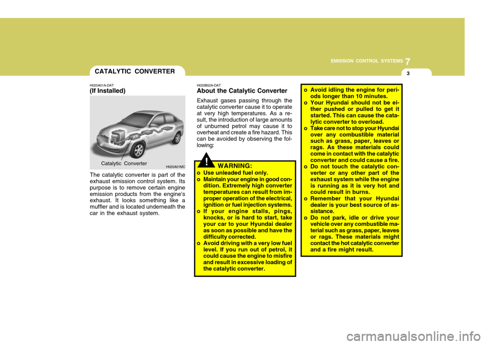
The catalytic converter is part of the
exhaust emission control system. Its purpose is to remove certain engineemission products from the engine's exhaust. It looks something like a muffler and is located underneath thecar in the exhaust system. H020B02A-DAT
About the Catalytic Converter
Exhaust gases passing through the
catalytic converter cause it to operate at very high temperatures. As a re- sult, the introduction of large amountsof unburned petrol may cause it to overheat and create a fire hazard. This can be avoided by observing the fol-lowing:
H020A01MCCatalytic Converter!WARNING:
o Use unleaded fuel only.
o Maintain your engine in good con- dition. Extremely high converter temperatures can result from im-proper operation of the electrical, ignition or fuel injection systems.
o If your engine stalls, pings, knocks, or is hard to start, takeyour car to your Hyundai dealer as soon as possible and have thedifficulty corrected.
o Avoid driving with a very low fuel
level. If you run out of petrol, it could cause the engine to misfire and result in excessive loading ofthe catalytic converter. o Avoid idling the engine for peri-
ods longer than 10 minutes.
o Your Hyundai should not be ei- ther pushed or pulled to get itstarted. This can cause the cata-lytic converter to overload.
o Take care not to stop your Hyundai over any combustible material such as grass, paper, leaves or rags. As these materials couldcome in contact with the catalytic converter and could cause a fire.
o Do not touch the catalytic con- verter or any other part of the exhaust system while the engineis running as it is very hot and could result in burns.
o Remember that your Hyundai dealer is your best source of as-sistance.
o Do not park, idle or drive your vehicle over any combustible ma- terial such as grass, paper, leavesor rags. These materials might contact the hot catalytic converter and a fire might result.
Page 225 of 232
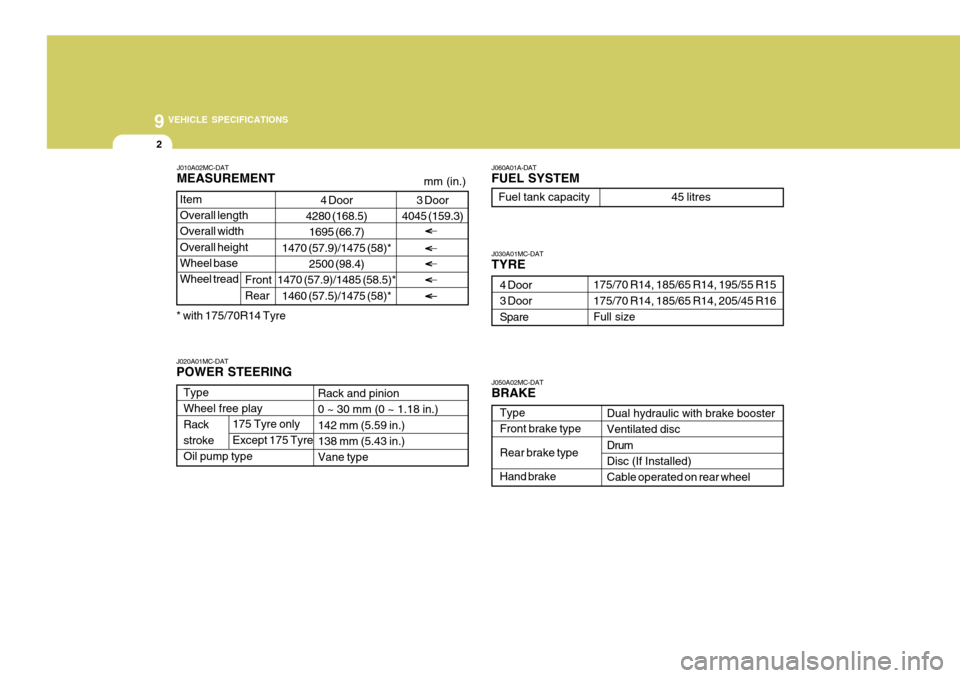
9 VEHICLE SPECIFICATIONS
2
Type Wheel free play Rackstroke Oil pump type J030A01MC-DAT TYRE
Dual hydraulic with brake booster Ventilated disc DrumDisc (If Installed) Cable operated on rear wheel
J060A01A-DAT FUEL SYSTEM
Rack and pinion 0 ~ 30 mm (0 ~ 1.18 in.) 142 mm (5.59 in.)138 mm (5.43 in.) Vane type
175/70 R14, 185/65 R14, 195/55 R15 175/70 R14, 185/65 R14, 205/45 R16 Full size
4 Door3 Door Spare
J020A01MC-DAT POWER STEERING Fuel tank capacity 45 litres
J050A02MC-DATBRAKE Type Front brake type Rear brake typeHand brake
175 Tyre only Except 175 Tyre
4 Door
4280 (168.5)
1695 (66.7)
1470 (57.9)/1475 (58)* 2500 (98.4)
1470 (57.9)/1485 (58.5)*
1460 (57.5)/1475 (58)*
Item Overall length Overall width Overall heightWheel base Wheel tread
J010A02MC-DAT MEASUREMENT
Front Rear
mm (in.)
3 Door
4045 (159.3)
* with 175/70R14 Tyre
Page 230 of 232
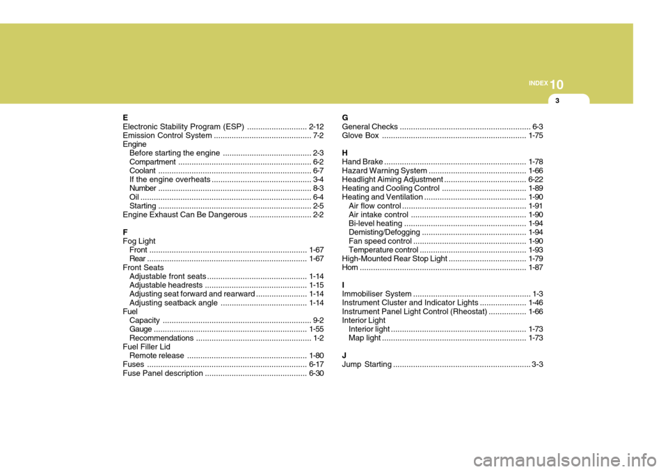
10
INDEX
3
E Electronic Stability Program (ESP) ...........................2-12
Emission Contro l System ............................................ 7-2
Engine Before starting the engine ........................................ 2-3Compartment ............................................................ 6-2
Coolant ..................................................................... 6-7
If the engine overheats ............................................. 3-4
Number ..................................................................... 8-3
Oil ............................................................................. 6-4 Starting ..................................................................... 2-5
Engine Exhaust Can Be Dangerous ............................ 2-2
FFog Light Front ....................................................................... 1-67
Rear ........................................................................ 1-67
Front Seats Adjustable front seats ............................................. 1-14
Adjustable headrests .............................................. 1-15
Adjusting seat forward and rearward .......................1-14
Adjusting seatback angle ....................................... 1-14
Fuel
Capacity ................................................................... 9-2
Gauge ..................................................................... 1-55
Recommendations .................................................... 1-2
Fuel Filler Lid
Remote release ...................................................... 1-80
Fuses ........................................................................ 6-17
Fuse Panel description .............................................. 6-30G General Checks
........................................................... 6-3
Glove Box ................................................................. 1-75
H Hand Brake ................................................................ 1-78
Hazard Warning System ............................................ 1-66
Headlight Aiming Adjustment..................................... 6-22
Heating and Cooling Control ......................................1-89
Heating and Ventilation .............................................. 1-90
Air flow control ........................................................ 1-91
Air intake control .................................................... 1-90
Bi-level heati ng ....................................................... 1-94
Demisting/Defogging ............................................... 1-94
Fan speed control ................................................... 1-90
Temperature control ................................................ 1-93
High-Mounted Rear Stop Light................................... 1-79
Horn ........................................................................... 1-87
IImmobiliser System ..................................................... 1-3
Instrument Cluster and Indicator Lights ..................... 1-46
Instrument Panel Light Control (Rheostat) .................1-66
Interior Light
Interior light ............................................................. 1-73
Map light ................................................................. 1-73
JJump Starting .............................................................. 3-3