2009 Hyundai Accent fuel
[x] Cancel search: fuelPage 151 of 232
2 DRIVING YOUR HYUNDAI
24
8. When parking your car and trailer,especially on a hill, be sure to follow all the normal precautions. Turn your front wheel into the curb, set the hand brake firmly, and put thetransaxle in 1st or Reverse (manual) or Park (automatic). In addition, place wheel chocks at each of thetrailer's tyres.
9. If the trailer has electric brakes,
drive your vehicle with the trailerattached, and then apply the trailer brakes by hand. This test confirms the operation of the trailer brakesand also checks your electrical con- nection at the same time.
10. During your trip, check occasionally to be sure that the load is secure,and that the lights and any trailer brakes are still working.
11.Avoid jerky starts, sudden accel- eration or sudden stops.
12.Avoid sharp turns and rapid lane changes.
13.Avoid holding the brake pedal down
too long or too frequently. This couldcause the brakes to overheat, re- sulting in reduced braking efficiency.
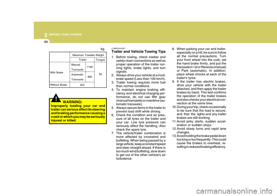
!WARNING:
Improperly loading your car and trailer can serious affect its steeringand braking performance causing a crash in which you may be seriously injured or killed. kg.
With Brake Without Brake
Maximum Towable Weight
1100800
Trailer Tongue
50
453
Manual TransaxleAutomaticTransaxle C190F01A-DAT Trailer and Vehicle Towing Tips
1. Before towing, check towbar and
safety chain connections as well as proper operation of the trailer run- ning lights, brake lights, and turn signals.
2. Always drive your vehicle at a mod- erate speed (Less than 100 km/h).
3. Trailer towing requires more fuel than normal conditions.
4. To maintain engine braking effi-
ciency and electrical charging per-formance, do not use fifth gear (manual transaxle) or overdrive (au- tomatic transaxle).
5. Always secure items in the trailer to prevent load shift while driving.
6. Check the condition and air pres- sure of all tyres on the trailer and your car. Low tyre pressure can seriously affect the handling. Alsocheck the spare tyre.
7. The vehicle/trailer combination is
more affected by crosswind andbuffeting. When being passed by a large vehicle, keep a constant speed and steer straight ahead. If there istoo much wind buffeting, slow down to get out of the other vehicle's air turbulence.
Page 154 of 232
3 WHAT TO DO IN AN EMERGENCY
2
!
IF THE ENGINE WILL NOT START
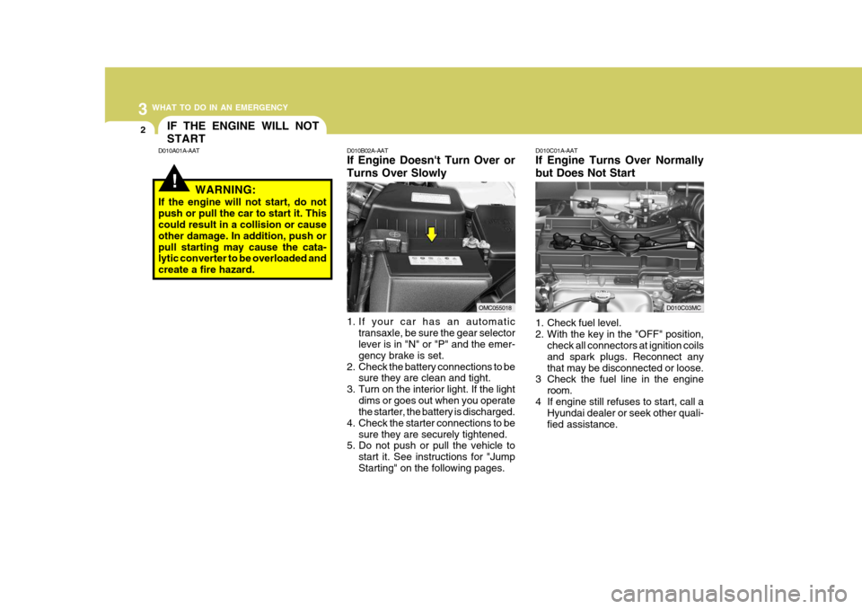
D010B02A-AAT If Engine Doesn't Turn Over or Turns Over Slowly
1. If your car has an automatic
transaxle, be sure the gear selector lever is in "N" or "P" and the emer- gency brake is set.
2. Check the battery connections to be sure they are clean and tight.
3. Turn on the interior light. If the light
dims or goes out when you operate the starter, the battery is discharged.
4. Check the starter connections to be
sure they are securely tightened.
5. Do not push or pull the vehicle to
start it. See instructions for "Jump Starting" on the following pages. D010C01A-AAT If Engine Turns Over Normally but Does Not Start
1. Check fuel level.
2. With the key in the "OFF" position,
check all connectors at ignition coilsand spark plugs. Reconnect anythat may be disconnected or loose.
3 Check the fuel line in the engine
room.
4 If engine still refuses to start, call a Hyundai dealer or seek other quali-fied assistance.
D010A01A-AAT
WARNING:
If the engine will not start, do notpush or pull the car to start it. This could result in a collision or cause other damage. In addition, push orpull starting may cause the cata- lytic converter to be overloaded and create a fire hazard.
OMC055018D010C03MC
Page 174 of 232
5VEHICLE MAINTENANCE REQUIREMENTS
2MAINTENANCE INTERVALS
F010C01A-DAT
Specified Scheduled Procedures
These are the procedures such as
inspections, adjustments and replace- ments that are listed in the mainte- nance charts starting on page 5-4.These procedures must be performed at the intervals shown in the mainte- nance schedule to assure that yourwarranty remains in effect. Although it is strongly recommended that they be performed by the factory-trainedor distributor-trained technicians at your Hyundai dealer, these proce- dures may be performed at any quali-fied service facility. It is suggested that genuine Hyundai service parts be used for any required repairs orreplacements. Other parts of equiva- lent quality such as engine oil, engine coolant, manual or auto transaxle oil,brake fluid and so on which are not supplied by Hyundai Motor Company or its distributor may be used withoutaffecting your warranty coverage but you should always be sure these are equivalent to the quality of the originalHyundai parts. Your Service Passport provides further information about your warranty coverage.
F010A01A-DAT
Service Requirements
To ensure that you receive satisfying
operation from your Hyundai, certain maintenance procedures must be per- formed. Although careful design andengineering have reduced these to a minimum, those that are required are of the utmost importance. It is your responsibility to have these
maintenance procedures performedto comply with the terms of the war- ranties covering your new Hyundai. The Service Passport supplied withyour new vehicle provides further in- formation about these warranties. F010D01A-AAT
General Checks
These are the regular checks you should perform each time you drive your Hyundai or you fill the fuel tank. A list of these items will be found onpage 6-3.
F010B01A-AAT Maintenance Requirements The maintenance required for your Hyundai can be divided into three main areas:
o Specified scheduled procedures
o General checks
o Do-it-yourself maintenance F010E01A-AAT
Do-It-Yourself Maintenance
If you are mechanically inclined, own a
few tools that are required and want to take the time to do so, you can inspect and service a number of items. Formore information about doing it your- self, see Section 6.
Page 176 of 232
5VEHICLE MAINTENANCE REQUIREMENTS
4REGULAR SERVICING
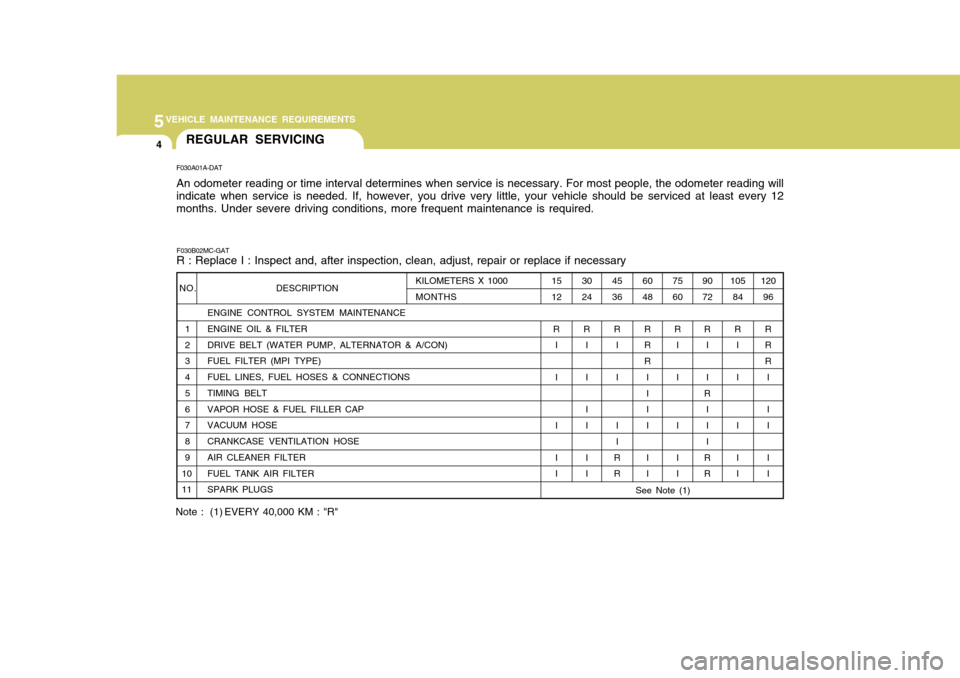
F030A01A-DAT An odometer reading or time interval determines when service is necessary. For most people, the odometer reading will indicate when service is needed. If, however, you drive very little, your vehicle should be serviced at least every 12 months. Under severe driving conditions, more frequent maintenance is required.
F030B02MC-GAT R : Replace I : Inspect and, after inspection, clean, adjust, repair or replace if necessary
ENGINE CONTROL SYSTEM MAINTENANCE
1 ENGINE OIL & FILTER
2 DRIVE BELT (WATER PUMP, ALTERNATOR & A/CON)
3 FUEL FILTER (MPI TYPE)
4 FUEL LINES, FUEL HOSES & CONNECTIONS
5 TIMING BELT
6 VAPOR HOSE & FUEL FILLER CAP
7 VACUUM HOSE
8 CRANKCASE VENTILATION HOSE
9 AIR CLEANER FILTER
10 FUEL TANK AIR FILTER
11 SPARK PLUGS
NO. DESCRIPTION105
84
R I I I I I 120
96
RR R I I I I I
90 72
R I I
R I I I
RR
75 60
R I I I I I
60 48
R R R II I I I I
45 36
R I I I I
RR
30 24
R I II I I I
15 12
R I I I I I
KILOMETERS X 1000 MONTHS
Note : (1) EVERY 40,000 KM : "R"
See Note (1)
Page 179 of 232
5
VEHICLE MAINTENANCE REQUIREMENTS
7EXPLANATION OF SCHED- ULED MAINTENANCE ITEMS
F060M01A-AAT
o Engine Oil and Filter
The engine oil and filter should be
changed at the intervals specified in the maintenance schedule. If the car is being driven in severe conditions,more frequent oil and filter changes are required. F060B01A-AAT
o Drive Belts
Inspect all drive belts for evidence of cuts, cracks, excessive wear or oilsaturation and replace if necessary. Drive belts should be checked period- ically for proper tension and adjustedas necessary. After installing a new filter, run the
engine for several minutes, and checkfor leaks at the connections. Fuel filters should be installed by trained technicians.
F060D01A-AAT
o Fuel Lines, Fuel Hoses and Connections
Check the fuel lines, fuel hoses and connections for leakage and damage. Have a trained technician replace any damaged or leaking parts immedi-ately. F060E01A-AAT
o Timing Belt Inspect all parts related to the timing belt for damage and deformation. Replace any damaged parts immedi-ately. F060G01A-AAT
o Vapor Hose and Fuel Filler Cap The vapor hose and fuel filler cap should be inspected at those inter- vals specified in the maintenanceschedule. Make sure that a new va- por hose or fuel filler cap is correctly replaced. F060F01A-AAT
o Vacuum, Crankcase Ventila-
tion Hoses
Inspect the surface of hoses for evi- dence of heat and/or mechanical dam- age. Hard and brittle rubber, crack- ing, tears, cuts, abrasions, and ex-cessive swelling indicate deteriora- tion. Particular attention should be paid to examine those hose surfacesnearest to high heat sources, such as the exhaust manifold. Inspect the hose routing to assure that the hoses do not come in contact with any heat source, sharp edges or moving component which might causeheat damage or mechanical wear. Inspect all hose connections, such as clamps and couplings, to make surethey are secure, and that no leaks are present. Hoses should be replaced immediately if there is any evidenceof deterioration or damage.
F060C01A-AAT
o Fuel Filter
A clogged filter can limit the speed at
which the vehicle may be driven, dam-age the emission system and cause hard starting. If an excessive amount of foreign matter accumulates in thefuel tank, the filter may require re- placement more frequently.
Page 186 of 232
6
DO-IT-YOURSELF MAINTENANCE
5
!
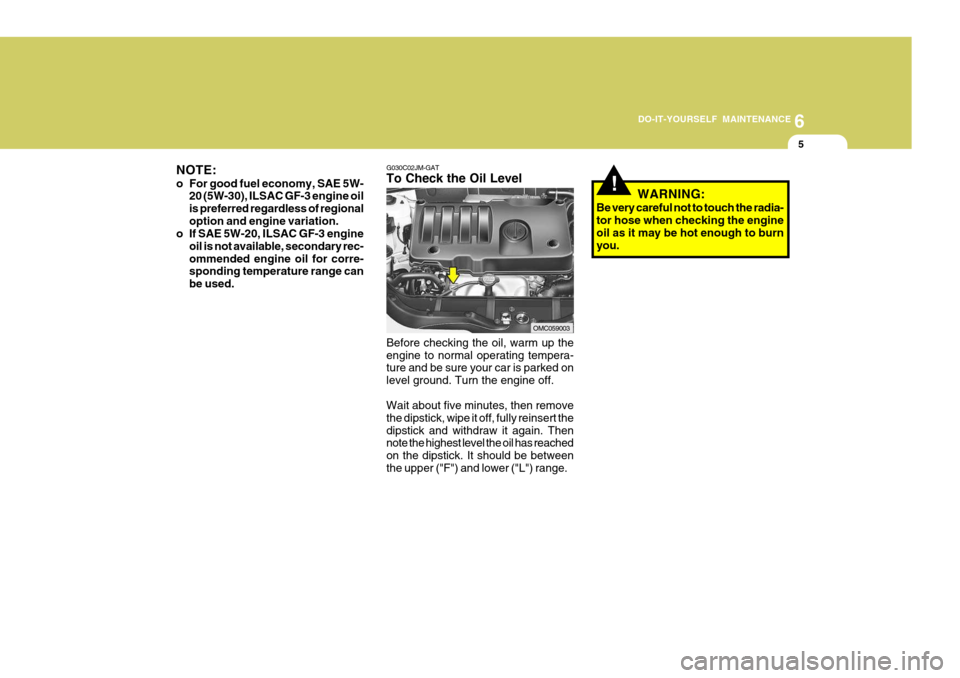
G030C02JM-GAT To Check the Oil Level Before checking the oil, warm up the engine to normal operating tempera- ture and be sure your car is parked on level ground. Turn the engine off. Wait about five minutes, then remove the dipstick, wipe it off, fully reinsert thedipstick and withdraw it again. Then note the highest level the oil has reached on the dipstick. It should be betweenthe upper ("F") and lower ("L") range.
NOTE:
o For good fuel economy, SAE 5W-
20 (5W-30), ILSAC GF-3 engine oil is preferred regardless of regionaloption and engine variation.
o If SAE 5W-20, ILSAC GF-3 engine
oil is not available, secondary rec-ommended engine oil for corre- sponding temperature range can be used.
OMC059003 WARNING:
Be very careful not to touch the radia- tor hose when checking the engine oil as it may be hot enough to burnyou.
Page 203 of 232
6 DO-IT-YOURSELF MAINTENANCE
22HEADLIGHT AIMING ADJUSTMENT
G290A03A-DAT Before performing aiming adjustment, make sure of the following.
1. Keep all tyres inflated to the correct
pressure.
2. Place the vehicle on level ground and press the front bumper & rear bumper down several times. Placethe vehicle at a distance of 3,000 mm (118 in.) from the test wall.
3. See that the vehicle is unloaded (except for full levels of coolant,engine oil and fuel, and spare tyre, jack, and tools).Have the driver or equivalent weight placed in driver's seat.
4. Clean the head light lenses and turn on the headlights (low beam).
NOTE:
o Grinding noise from the power
steering pump may be heard im- mediately after the engine is startedin extremely cold conditions (be- low - 20°C). If the noise stops during warm up, there is no ab-normal function in the system. It is due to a power steering fluid characteristic in extremely coldconditions.
o Do not start the engine when the
power steering oil reservoir isempty. G240A01A-DAT POWER STEERING HOSES It is suggested that you check the power steering hose connections forfluid leakage at those intervals speci- fied in the vehicle maintenance sched- ule in Section 5. The power steeringhoses should be replaced if there is severe surface cracking, pulling, scuff- ing or worn spots. Deterioration of thehoses could cause premature failure.
Page 211 of 232
6 DO-IT-YOURSELF MAINTENANCE
30FUSE PANEL DESCRIPTION
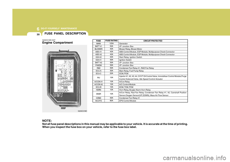
G200C01MC-DAT Engine Compartment NOTE: Not all fuse panel descriptions in this manual may be applicable to your vehicle. It is accurate at the time of printing. When you inspect the fuse box on your vehicle, refer to the fuse box label.
G200C01MC FUSE RATING
125A50A 40A 40A 40A40A 30A 30A30A 30A 30A20A 15A10A 10A 10A10A 10A30A 80A CIRCUIT PROTECTED
GeneratorI/P Junction Box
Blower Relay, Blower MotorABS Control Module, ESP Module, Multipurpose Check Connector ABS Control Module, ESP Module, Multipurpose Check Connector
Start Relay, Ignition SwitchIgnition Switch I/P Junction Box I/P Junction BoxCondenser Fan Relay #1, RAD Fan Relay
Main Relay, Fuel Pump Relay ECM, PCM
Injector #1, #2, #3, #4, CVVT Oil Control Valve, Immobiliser Control Module,Purge
Control Solenoid Valve, Idle Speed Control Actuator A/Con RelayA/C Control ModuleECM, TCM, PCM
Horn Relay, Burglar Alarm Horn Relay
A/Con Relay, Rad Fan Relay, Condenser Fan Relay #1, #2, Camshaft Position
Sensor,Oxygen Sensor(UP, DOWN), Mass Air Flow Sensor Condenser Fan Relay #1 EPS Control Module
MAIN
BATT #1
BLOWER
ABS #1 ABS #2IGN #2 IGN #1
BATT #2 P/WDW
RAD
ECU A ECU C
INJ
A/CON #1 A/CON #2 ECU BHORN
SNSR
COND
M.D.P.S
FUSE