2009 DODGE RAM 2500 DIESEL wheel torque
[x] Cancel search: wheel torquePage 201 of 532

CAUTION!
The TPMS has been optimized for the original
equipment tires and wheels. TPMS pressures and
warning have been established for the tire size
equipped on your vehicle. Undesirable system opera-
tion or sensor damage may result when using re-
placement equipment that is not of the same size,
type, and/or style. Aftermarket wheels can cause
sensor damage. Do not use tire sealant from a can, or
balance beads if your vehicle is equipped with a
TPMS, as damage to the sensors may result.
26. Electronic Stability Program (ESP) Indicator Light/
Traction Control System (TCS) Indicator Light — If
Equipped If this indicator light flashes during accelera-
tion, apply as little throttle as possible. While
driving, ease up on the accelerator. Adapt your speed and driving to the prevailing road conditions, and
do not switch off the Electronic Stability Program (ESP),
or Traction Control System (TCS).
27. Transmission Temperature Indicator (Automatic
Transmissions Only)
This light indicates that there is excessive trans-
mission fluid temperature that might occur
with severe usage such as trailer towing. It may
also occur when operating the vehicle in a high
torque converter slip condition, such as 4-wheel-drive
operation (e.g., snow plowing, off- road operation). If this
light comes on, stop the vehicle and run the engine at idle
or faster, with the transmission in NEUTRAL until the
light goes off.
28. Odometer/Trip Odometer Button
Press this button to toggle between the odometer and the
trip odometer display. Holding the button in resets the
trip odometer reading when in trip mode.
UNDERSTANDING YOUR INSTRUMENT PANEL 199
4
Page 262 of 532
the upper gears. When the vehicle speed drops or during
acceleration when the transmission downshifts to second
gear, the clutch automatically disengages.
NOTE:•
The torque converter clutch will not engage until the
transmission fluid and engine coolant are warm [usu-
ally after 1-3 miles (1.6 - 4.8 km) of driving]. Because
the engine speed is higher when the torque converter
clutch is not engaged, it may seem as if the transmis-
sion is not shifting into Overdrive when cold. This is
normal. Pressing the “TOW HAUL O/D OFF” button,
when the transmission is sufficiently warm, will dem-
onstrate that the transmission is able to shift into and
out of overdrive.
•
If the vehicle has not been driven in several days, the
first few seconds of operation after shifting the trans-
mission into gear may seem sluggish. This is due to the
fluid partially draining from the torque converter intothe transmission. This condition is normal and will not
cause damage to the transmission. The torque con-
verter will refill within five seconds of shifting from
PARK into any other gear position.
FOUR-WHEEL DRIVE OPERATION — IF
EQUIPPEDFour-wheel drive trucks are equipped with either a
manually shifted transfer case or an electronically shifted
transfer case. Refer to the operating instructions for your
transfer case, located in this section.Manually Shifted Transfer Case Operating
Information/PrecautionsThe transfer case provides four mode positions.•
Two-wheel drive high range (2H)
•
Four-wheel drive high range (4H)
•
Neutral (N)
•
Four-wheel drive low range (4L)
260 STARTING AND OPERATING
Page 282 of 532
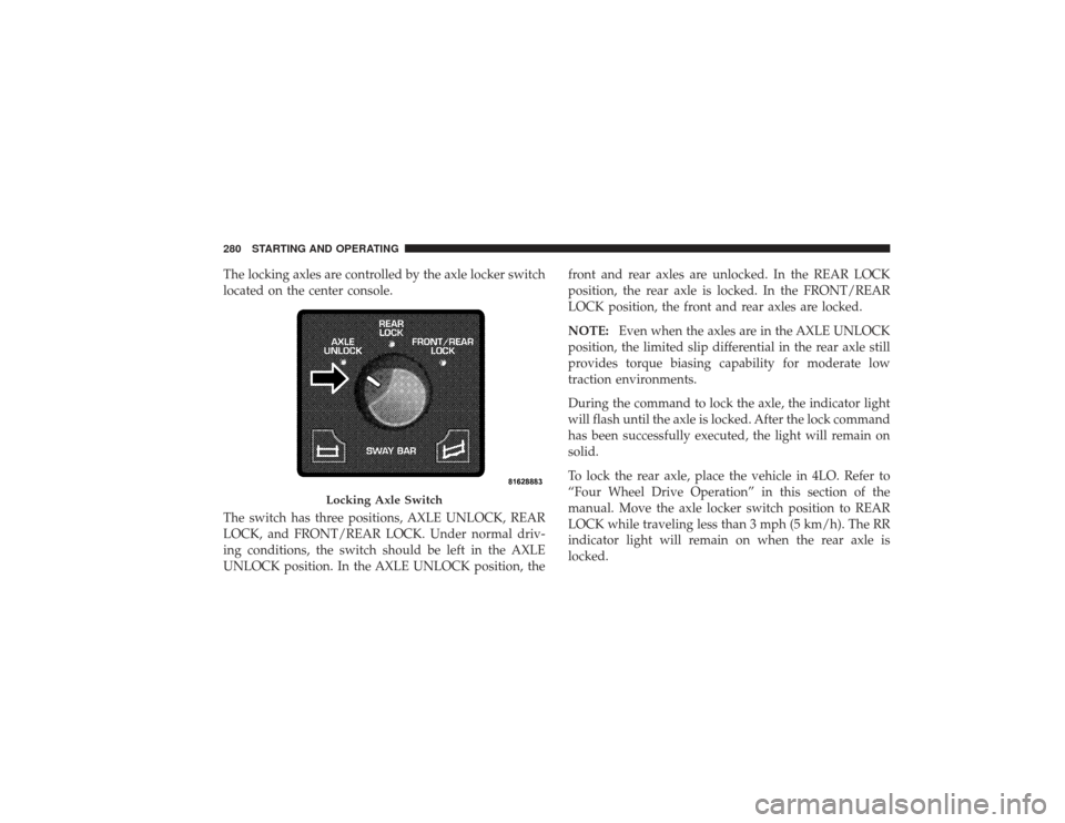
The locking axles are controlled by the axle locker switch
located on the center console.
The switch has three positions, AXLE UNLOCK, REAR
LOCK, and FRONT/REAR LOCK. Under normal driv-
ing conditions, the switch should be left in the AXLE
UNLOCK position. In the AXLE UNLOCK position, thefront and rear axles are unlocked. In the REAR LOCK
position, the rear axle is locked. In the FRONT/REAR
LOCK position, the front and rear axles are locked.
NOTE:
Even when the axles are in the AXLE UNLOCK
position, the limited slip differential in the rear axle still
provides torque biasing capability for moderate low
traction environments.
During the command to lock the axle, the indicator light
will flash until the axle is locked. After the lock command
has been successfully executed, the light will remain on
solid.
To lock the rear axle, place the vehicle in 4LO. Refer to
“Four Wheel Drive Operation” in this section of the
manual. Move the axle locker switch position to REAR
LOCK while traveling less than 3 mph (5 km/h). The RR
indicator light will remain on when the rear axle is
locked.
Locking Axle Switch
280 STARTING AND OPERATING
Page 283 of 532
NOTE:Left to right wheel speed difference may be
necessary to allow the axle to fully lock. If the indicator
light is flashing after placing the switch in the REAR
LOCK or FRONT/REAR LOCK position, drive the ve-
hicle in a turn or on loose gravel to expedite the locking
action.
WARNING!
Do not use the locked axle position for normal
driving. A locked front axle is intended for off-road
driving only. Locking the front axle during on-road
driving will reduce the steering ability. This could
cause an accident and you may be seriously injured.
To lock the front axle; move the axle locker switch to
FRONT/REAR LOCK while traveling less than 3 mph
(5 km/h). The indicator light will be solid when the front
axle is locked. NOTE:
The rear axle must be locked before the front
axle will lock.
To unlock the front axle; move the axle locker switch to
REAR LOCK. The FRONT/REAR LOCK indicator light
will go out when the axle is unlocked.
NOTE: The axle lockers could be torque locked due to
side to side loads on the axle. Driving slowly while
turning the steering wheel from a left hand turn to a right
hand turn or driving in REVERSE for a short distance
may be required to release the torque lock and unlock the
axles.
To unlock the rear axle; move the axle locker switch to
AXLE UNLOCK. The REAR LOCK indicator light will go
out when the rear axle is unlocked.
STARTING AND OPERATING 281
5
Page 285 of 532
WARNING!
Do not disconnect the stabilizer bar and drive on
hard surfaced roads or at speeds above 18 mph
(29 km/h), you may lose control of the vehicle, which
could result in serious injury. The front stabilizer bar
enhances vehicle stability and is necessary for main-
taining control of the vehicle. The system monitors
vehicle speed and will attempt to reconnect the
stabilizer bar at speeds over 18 mph (29 km/h). This is
indicated by a flashing off road light and solid on
road light. Once vehicle speed is reduced below
14 mph (22 km/h), the system will attempt to return to
the Off-Road mode.
To disconnect the stabilizer/sway bar, shift to either 4HI
or 4LO as shown in “Four Wheel Drive Operation” and
press the top of the stabilizer/sway bar button to obtain the Off-Road position. The amber indicator light will
flash until the stabilizer/sway bar has been fully discon-
nected.
NOTE:
The stabilizer/sway bar may be torque locked
due to left and right suspension height differences. This
condition is due to driving surface differences or vehicle
loading. In order for the stabilizer/sway bar to
disconnect/reconnect, the right and left halves of the bar
must be aligned. This alignment may require that the
vehicle be driven onto level ground or rocked from side
to side.
To return to the On-Road mode; press the bottom of the
stabilizer/sway bar button.
STARTING AND OPERATING 283
5
Page 305 of 532
•
Completely inspect the underbody of your vehicle.
Check tires, body structure, steering, suspension, and
exhaust system for damage.
•
Check threaded fasteners for looseness, particularly on
the chassis, drivetrain components, steering, and sus-
pension. Retighten them, if required, and torque to the
values specified in the Service Manual.
•
Check for accumulations of plants or brush. These
things could be a fire hazard, or they might hide
damage to fuel lines, brake hoses, axle pinion seals,
and propeller shafts.
•
After extended operation in mud, sand, water, or
similar dirty conditions, have brake drums and rotors,
brake linings, and axle yokes inspected and cleaned as
soon as possible.
•
If you experience unusual vibration after driving in
mud, slush or similar conditions, check the wheels for
packed material. Packed foreign material can cause a
wheel imbalance and cleaning the wheels will correct
the situation.
WARNING!
Abrasive material in any part of the brakes may cause
excessive wear or unpredictable braking. You might
not have full braking power when you need it to
prevent an accident. If you have been operating your
vehicle in dirty conditions, get your brakes checked
and cleaned as necessary. Failure to do so may result
is serious injury.
STARTING AND OPERATING 303
5
Page 336 of 532
NOTE:ABS improves steering control of the vehicle
during hard braking maneuvers.
WARNING!
•
ABS cannot prevent the natural laws of physics
from acting on the vehicle, nor can it increase
braking or steering efficiency beyond that af-
forded by the condition of the vehicle brakes and
tires or the traction afforded.
•
The ABS cannot prevent accidents, including
those resulting from excessive speed in turns,
following another vehicle too closely, or hydro-
planing. Only a safe, attentive, and skillful driver
can prevent accidents.
•
The capabilities of an ABS-equipped vehicle must
never be exploited in a reckless or dangerous
manner which could jeopardize the user’s safety
or the safety of others.
Traction Control System (TCS)The TCS monitors the amount of wheel spin of each of
the driven wheels. If wheel spin is detected, brake
pressure is applied to the slipping wheel(s), and engine
power is reduced to provide enhanced acceleration and
stability. A feature of the TCS functions similar to a
limited-slip differential and controls the wheel spin
across a driven axle. If one wheel on a driven axle is
spinning faster than the other, the system will apply the
brake of the spinning wheel. This will allow more engine
torque to be applied to the wheel that is not spinning.
This feature remains active even if TCS and ESP are in the
“Partial Off” mode. Refer to “Electronic Stability Pro-
gram (ESP)” in this section of this manual. This brake
pressure modulation transfers drive torque from slipping
to non-slipping wheels to provide optimal forward
traction.
334 STARTING AND OPERATING
Page 416 of 532
face. Lightly tighten the nuts. To avoid risk of forcing the
vehicle off the jack, do not fully tighten the nuts until the
vehicle has been lowered.
6. Using the wheel wrench, finish tightening the nuts
using a crisscross pattern. The correct nut tightness is
135 ft lbs (183 N·m) torque for 2500/3500 single-rear
wheel (SRW) models, and 145 ft lbs (197 N·m) for 3500
dual rear-wheel models. If in doubt about the correct
tightness, have them checked with a torque wrench by
your authorized dealer or at a service station.
WARNING!
A loose tire or jack thrown forward in a collision or
hard stop could injure someone in the vehicle. Al-
ways stow the jack parts and the extra tire and wheel
in the places provided.7. Install wheel center cap and remove wheel blocks. Do
not install chrome or aluminum wheel center caps on the
spare wheel. This may result in cap damage.
8. Lower the jack to its fully closed position. If the bottle
jack will not lower by turning the dial (thumbwheel) by
hand, it may be necessary to use the jack drive tube in
order to lower the jack. Stow the replaced tire, jack, and
tools as previously described.
9. Adjust the tire pressure when possible.
NOTE:
Do not oil wheel studs. For chrome wheels, do
not substitute with chrome plated wheel nuts.
Hub Caps/Wheel CoversThe hub caps must be removed before raising the vehicle
off the ground.
For 2500/3500 single rear-wheel (SRW) models, use the
blade on the end of the lug wrench to pry the hub cap off.
414 WHAT TO DO IN EMERGENCIES