Page 1701 of 1903
Downloaded from www.Manualslib.com manuals search engine Diagnostic Trouble Code (DTC) Tests
B1000 - ECU Defect: Internal Errors
DIAGNOSIS & TESTING
LTSMW150081T
15
15–11 7Chery Automobile Co., Ltd.
Page 1702 of 1903

Downloaded from www.Manualslib.com manuals search engine On Board Diagnostic Logic
•Self-diagnosis detection logic.
DTC NO. DTC DEFINITION DTC DETECTION
CONDITION POSSIBLE CAUSE
B1000 ECU Defect, Internal
Errors Immobilizer control
module detects an internal failure. •
Immobilizer control
module
DTC Confirmation Procedure:
Before performing the following procedure, confirm that battery voltage is more than 12 V.
•Turn ignition switch off.
• Connect the X-431 scan tool to the Data Link Connector (DLC) - use the most current software available.
• Turn ignition switch on, with the scan tool, view and erase stored DTCs in the Immobilizer control module.
• Try to start the engine.
• Turn ignition switch off, and wait a few seconds, then turn ignition switch on.
• With the scan tool, view DTCs in the Immobilizer control module.
• If the DTC is detected, the condition is current. Go to Diagnostic Procedure - Step 1.
• If the DTC is not detected, the DTC condition is intermittent (See Diagnostic Help and Intermittent DTC Trou-
bleshooting in Section 15 Body & Accessories for more information).
NOTE :
While performing electrical diagnosis & testing, always refer to the electrical schematics for specific circuit
and component information.
Diagnostic Procedure
1.CHECK DTC
• Perform DTC confirmation procedure.
Is DTC B1000 present?
Ye s>>Go to the next step.
No
>>The condition that caused the DTC to set is currently not present (See Diagnosis & Testing Diagnostic
Help in Section 15 Body & Accessories).
2.CHECK IMMOBILIZER CONTROL MODULE ELECTRICAL CONNECTOR
• Turn ignition switch off.
• Disconnect the Immobilizer control module electrical
connector C-025 (1).
• Inspect the electrical connector for damage.
Is the electrical connector OK?
Ye s>>Go to the next step.
No
>>Repair or replace the electrical connector
as necessary.
DIAGNOSIS & TESTING
LTSMD150019
15–11 8Chery Automobile Co., Ltd.
Page 1726 of 1903
Downloaded from www.Manualslib.com manuals search engine 6.PROGRAM THE TRANSPONDER
• Turn ignition switch on.
• Using the X-431 scan tool, program the vehicle security system.
•
• Turn ignition switch on and perform the following:
� With the X-431 scan tool, choose T11 series.
� Choose �immobilize�.
� Input the safety code.
� Click the small keyboard.
� Click �OK�.
� Choose �Immobilizer adapt�.
� Choose �Key learning� immediately.
� Click �OK�.
• Try to start the engine.
• With the X-431 scan tool, view active DTCs in the Immobilizer control module.
Is DTC B3060, B3061 or B3077 present?
Ye s>>Go to the next step.
No
>>No problem found at this time.
This concern may have been caused by the not programmed transponder.
Erase all codes before returning the vehicle to the customer.
7.REPLACE AND PROGRAM THE TRANSPONDER
• Replace the chip (1) with a new one.
DIAGNOSIS & TESTING
VISMD150019T
VISMD150018
15–142Chery Automobile Co., Ltd.
Page 1837 of 1903
Downloaded from www.Manualslib.com manuals search engine Locking Connector
•When locking connectors, listen for a click indicat-
ing they are securely locked.
Connector Terminals
•Pull lightly on individual wires to check that they
are secured in the terminal.
Connector/Terminal Replacement
•Use the appropriate tools to remove a terminal as
shown. While installing a terminal, be sure to insert
it until it locks securely.
• Insert a thin piece of metal from the terminal side
of the connector and with the terminal locking tab
pressed down, pull the terminal out from the
connector.
ELECTRICAL COMPONENTS
BESM010020
BESM010023
BESM010029
16
16–11Chery Automobile Co., Ltd.
Page 1864 of 1903

Downloaded from www.Manualslib.com manuals search engine GENERAL INFORMATION
Description
In order to ensure the normal operation of the system, every electrical system is equipped with fuses and relays. The
fuses and relays are stored in the fuse boxes.
The vehicle fuses and relays are located in the following locations:
•Power Fuse Box
• Front Fuse and Relay Box
• Body Fuse and Relay Box
Operation
When replacing a open fuse, it is important to use only a fuse having the correct amperage rating. The use of a fuse
with a rating other than indicated may result in a dangerous electrical system overload. If a properly rated fuse con-
tinues to open, it indicates a problem in the circuit that must be corrected.
Power Fuse Box
Description
The power fuse box is located on the side of the battery. All of the electrical current distributed throughout the vehicle
is directed through the power fuse box. The power fuse box houses five maxi-type bolt in fuses.
Operation
All of the current from the battery and the generator output enters the power fuse box through the cable and eyelet
that are secured with a nut to the power fuse box B(+) terminal stud located on one end of the power fuse box
housing. The power fuse box terminal stud cover is unlatched and opened to access the fuses.
16–38Chery Automobile Co., Ltd.
Page 1885 of 1903

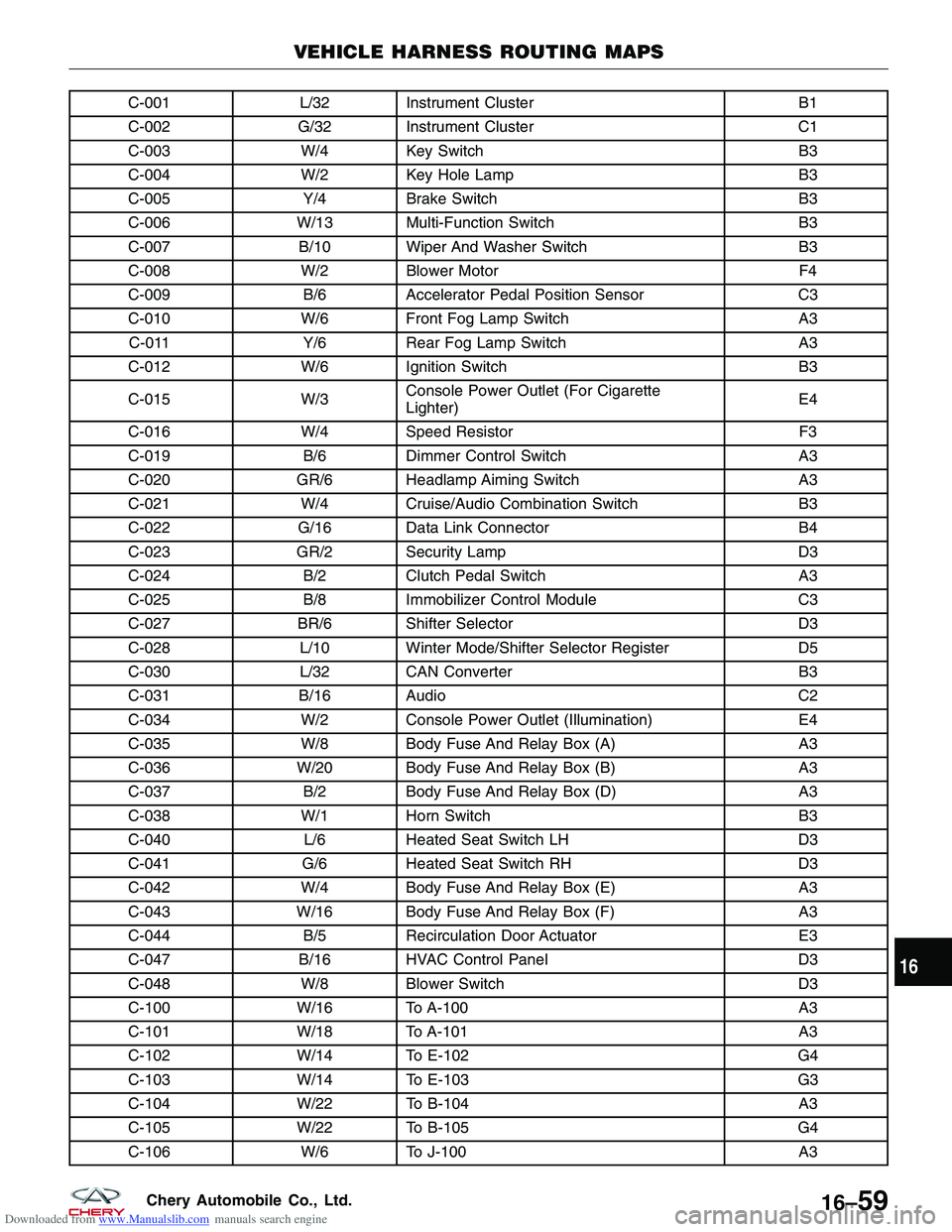
Downloaded from www.Manualslib.com manuals search engine C-001L/32 Instrument Cluster B1
C-002 G/32 Instrument Cluster C1
C-003 W/4 Key Switch B3
C-004 W/2 Key Hole Lamp B3
C-005 Y/4Brake Switch B3
C-006 W/13 Multi-Function Switch B3
C-007 B/10 Wiper And Washer Switch B3
C-008 W/2 Blower Motor F4
C-009 B/6Accelerator Pedal Position Sensor C3
C-010 W/6 Front Fog Lamp Switch A3
C-011 Y/6Rear Fog Lamp Switch A3
C-012 W/6 Ignition Switch B3
C-015 W/3Console Power Outlet (For Cigarette
Lighter) E4
C-016 W/4 Speed Resistor F3
C-019 B/6Dimmer Control Switch A3
C-020 GR/6 Headlamp Aiming Switch A3
C-021 W/4 Cruise/Audio Combination Switch B3
C-022 G/16 Data Link Connector B4
C-023 GR/2 Security Lamp D3
C-024 B/2Clutch Pedal Switch A3
C-025 B/8Immobilizer Control Module C3
C-027 BR/6 Shifter Selector D3
C-028 L/10 Winter Mode/Shifter Selector Register D5
C-030 L/32 CAN Converter B3
C-031 B/16 Audio C2
C-034 W/2 Console Power Outlet (Illumination) E4
C-035 W/8 Body Fuse And Relay Box (A) A3
C-036 W/20 Body Fuse And Relay Box (B) A3
C-037 B/2Body Fuse And Relay Box (D) A3
C-038 W/1 Horn Switch B3
C-040 L/6Heated Seat Switch LH D3
C-041 G/6Heated Seat Switch RH D3
C-042 W/4 Body Fuse And Relay Box (E) A3
C-043 W/16 Body Fuse And Relay Box (F) A3
C-044 B/5Recirculation Door Actuator E3
C-047 B/16 HVAC Control Panel D3
C-048 W/8 Blower Switch D3
C-100 W/16 To A-100 A3
C-101 W/18 To A-101 A3
C-102 W/14 To E-102 G4
C-103 W/14 To E-103 G3
C-104 W/22 To B-104 A3
C-105 W/22 To B-105 G4
C-106 W/6 To J-100 A3
VEHICLE HARNESS ROUTING MAPS
16
16–59Chery Automobile Co., Ltd.