Page 1212 of 1903
Downloaded from www.Manualslib.com manuals search engine 10. Align the selector finger (1) and fork shaft springpin (2), install the spring pin of selector finger (as
shown by the arrow in the figure).
11. Tighten the interlock plate limit bolt (1) together with the shim to the housing (as shown in the fig-
ure). The tightening torque of the bolt is 30 N·m.
Check front end circular cylinder of the bolt to
ensure it is in the corresponding groove of selector
finger.
12. Check the gearshift shaft to ensure it is able to rotate and perform axial movement freely.
13. Install air duct (1) and air duct cap (2). Apply seal- ant to the surface of the inserted part of air duct.
14. Install the backup light switch assembly (1). (Tighten: Backup light switch to 32 N·m)
ON-VEHICLE SERVICE
LTSM080094
LTSM080128
LTSM080134
LTSM080135
08
08–269Chery Automobile Co., Ltd.
Page 1217 of 1903
Downloaded from www.Manualslib.com manuals search engine Inspection
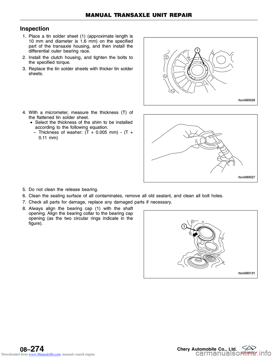
1. Place a tin solder sheet (1) (approximate length is10 mm and diameter is 1.6 mm) on the specified
part of the transaxle housing, and then install the
differential outer bearing race.
2. Install the clutch housing, and tighten the bolts to the specified torque.
3. Replace the tin solder sheets with thicker tin solder sheets.
4. With a micrometer, measure the thickness (T) of the flattened tin solder sheet.• Select the thickness of the shim to be installed
according to the following equation.
� Thickness of washer: (T + 0.005 mm) - (T +
0.11 mm)
5. Do not clean the release bearing.
6. Clean the sealing surface of all contaminates, remove all old sealant, and clean all bolt holes.
7. Check all parts for damage, replace any damaged parts if necessary.
8. Always align the bearing cap (1) with the shaft opening. Align the bearing collar to the bearing cap
opening (as the two circular rings indicate in the
figure).
MANUAL TRANSAXLE UNIT REPAIR
LTSM080026
LTSM080027
LTSM080131
08–274Chery Automobile Co., Ltd.
Page 1241 of 1903
Downloaded from www.Manualslib.com manuals search engine Assemble
Assemble in the reverse order of disassembly.
NOTE :
•Check and ensure the shift fork is properly installed to the fork shaft, there should be NO axial or radial motion in
the fork shaft.
• Check and ensure the fork rack is properly installed to the fork shaft, there should be NO axial or radial motion in
the fork shaft.
• Check and ensure backup light driving block is properly installed to the fork shaft, there should be NO axial or
radial motion in the fork shaft.
• Check the fork shaft surface for any damage.
• Check the position of the three spring pins, ensure the pins are in proper alignment. The extension of both ends
of the three spring pins should not exceed 3 mm.
3rd-4th Gear Shift Fork
Disassemble
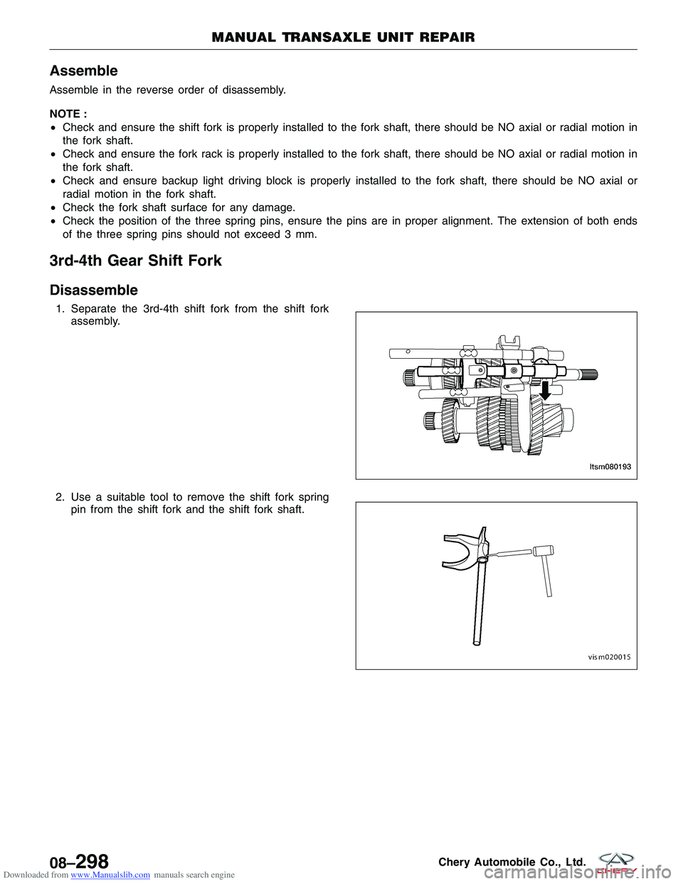
1. Separate the 3rd-4th shift fork from the shift fork
assembly.
2. Use a suitable tool to remove the shift fork spring pin from the shift fork and the shift fork shaft.
MANUAL TRANSAXLE UNIT REPAIR
LTSM080193
VISM020015
08–298Chery Automobile Co., Ltd.
Page 1242 of 1903
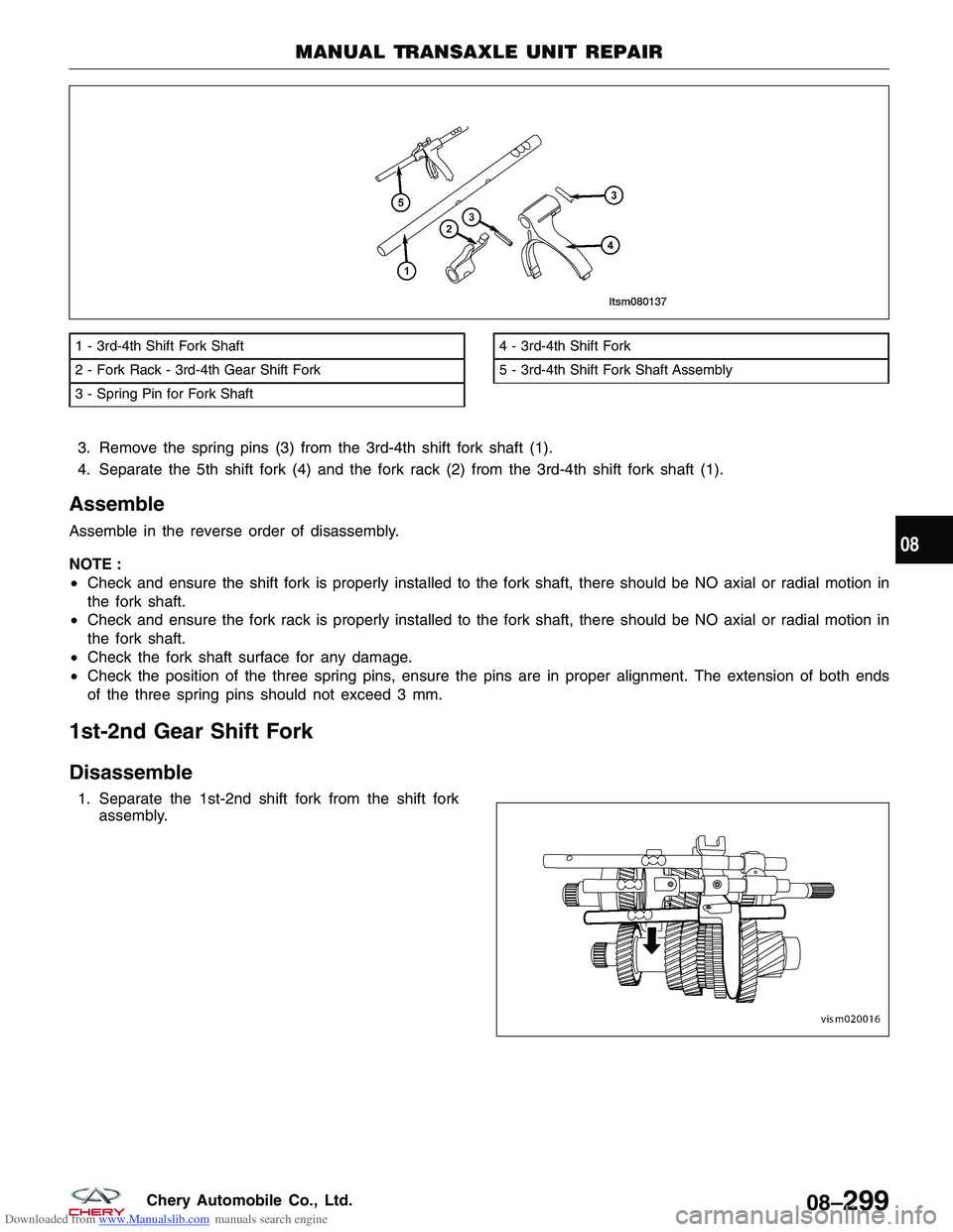
Downloaded from www.Manualslib.com manuals search engine 3. Remove the spring pins (3) from the 3rd-4th shift fork shaft (1).
4. Separate the 5th shift fork (4) and the fork rack (2) from the 3rd-4th shift fork shaft (1).
Assemble
Assemble in the reverse order of disassembly.
NOTE :
•Check and ensure the shift fork is properly installed to the fork shaft, there should be NO axial or radial motion in
the fork shaft.
• Check and ensure the fork rack is properly installed to the fork shaft, there should be NO axial or radial motion in
the fork shaft.
• Check the fork shaft surface for any damage.
• Check the position of the three spring pins, ensure the pins are in proper alignment. The extension of both ends
of the three spring pins should not exceed 3 mm.
1st-2nd Gear Shift Fork
Disassemble
1. Separate the 1st-2nd shift fork from the shift fork
assembly.
1 - 3rd-4th Shift Fork Shaft
2 - Fork Rack - 3rd-4th Gear Shift Fork
3 - Spring Pin for Fork Shaft4 - 3rd-4th Shift Fork
5 - 3rd-4th Shift Fork Shaft Assembly
MANUAL TRANSAXLE UNIT REPAIR
LTSM080137
VISM020016
08
08–299Chery Automobile Co., Ltd.
Page 1243 of 1903

Downloaded from www.Manualslib.com manuals search engine 2. Use a suitable tool to remove the shift fork springpin from the shift fork and the shift fork shaft.
3. Remove the spring pins (3) from the 1st-2nd shift fork shaft (1).
4. Separate the 1st-2nd shift fork (4) and the fork rack (2) from the 1st-2nd shift fork shaft (1).
Assembly
Assemble in the reverse order of disassembly.
NOTE :
• Check and ensure the shift fork is properly installed to the fork shaft, there should be NO axial or radial motion in
the fork shaft.
• Check and ensure the fork rack is properly installed to the fork shaft, there should be NO axial or radial motion in
the fork shaft.
• Check the fork shaft surface for any damage.
• Check the position of the three spring pins, ensure the pins are in proper alignment. The extension of both ends
of the three spring pins should not exceed 3 mm.
1 - 1st-2nd Shift Fork Shaft
2 - Fork Rack - 1st-2nd Gear Shift Fork
3 - Spring Pin for Fork Shaft4 - 1st-2nd Shift Fork
5 - 1st-2nd Shift Fork Shaft Assembly
MANUAL TRANSAXLE UNIT REPAIR
VISM020015
LTSM080141
08–300Chery Automobile Co., Ltd.
Page 1263 of 1903
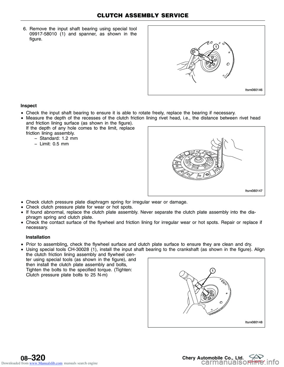
Downloaded from www.Manualslib.com manuals search engine 6. Remove the input shaft bearing using special tool09917-58010 (1) and spanner, as shown in the
figure.
Inspect
• Check the input shaft bearing to ensure it is able to rotate freely, replace the bearing if necessary.
• Measure the depth of the recesses of the clutch friction lining rivet head, i.e., the distance between rivet head
and friction lining surface (as shown in the figure).
If the depth of any hole comes to the limit, replace
friction lining assembly.
� Standard: 1.2 mm
� Limit: 0.5 mm
• Check clutch pressure plate diaphragm spring for irregular wear or damage.
• Check clutch pressure plate for wear or hot spots.
• If found abnormal, replace the clutch plate assembly. Never separate the clutch plate assembly into the dia-
phragm spring and clutch plate.
• Check the contact surface of the flywheel and friction lining for irregular wear or hot spots. Repair or replace if
necessary.
Installation
• Prior to assembling, check the flywheel surface and clutch plate surface to ensure they are clean and dry.
• Using special tools CH-30028 (1), install the input shaft bearing to the crankshaft (as shown in the figure). Align
the clutch friction lining assembly and flywheel cen-
ter using special tools (as shown in the figure), and
then install the clutch plate assembly and bolts,
Tighten the bolts to the specified torque. (Tighten:
Clutch pressure plate bolts to 25 N·m)
CLUTCH ASSEMBLY SERVICE
LTSM080146
LTSM080147
LTSM080148
08–320Chery Automobile Co., Ltd.
Page 1264 of 1903
Downloaded from www.Manualslib.com manuals search engine NOTE :
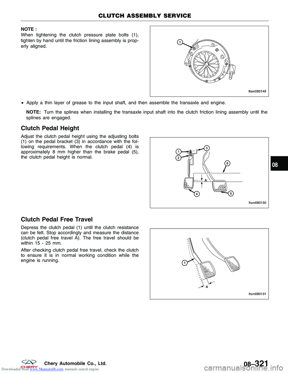
When tightening the clutch pressure plate bolts (1),
tighten by hand until the friction lining assembly is prop-
erly aligned.
•Apply a thin layer of grease to the input shaft, and then assemble the transaxle and engine.
NOTE: Turn the splines when installing the transaxle input shaft into the clutch friction lining assembly until the
splines are engaged.
Clutch Pedal Height
Adjust the clutch pedal height using the adjusting bolts
(1) on the pedal bracket (3) in accordance with the fol-
lowing requirements. When the clutch pedal (4) is
approximately 8 mm higher than the brake pedal (5),
the clutch pedal height is normal.
Clutch Pedal Free Travel
Depress the clutch pedal (1) until the clutch resistance
can be felt. Stop accordingly and measure the distance
(clutch pedal free travel A). The free travel should be
within 15 - 25 mm.
After checking clutch pedal free travel, check the clutch
to ensure it is in normal working condition while the
engine is running.
CLUTCH ASSEMBLY SERVICE
LTSM080149
LTSM080150
LTSM080151
08
08–321Chery Automobile Co., Ltd.
Page 1267 of 1903
Downloaded from www.Manualslib.com manuals search engine Clutch Slave Cylinder
Removal & Installation
NOTE :
After replacing the slave cylinder, it is necessary to make sure brake master cylinder fluid level is full and the res-
ervoir cap is installed tightly.1. Remove the clutch master cylinder outlet pipe (1) from the clutch slave cylinder.
(Tighten: Outlet pipe bolt to 17 ± 1 N·m)
2. Remove the clutch slave cylinder bolts (1) from the transaxle housing.
(Tighten: Clutch slave cylinder bolts to 11 ± 1 N·m)
3. Installation is in the reverse order of removal.
4. Bleed the hydraulic clutch (See Bleeding Hydraulic Clutch in Section 08 Transaxle). NOTE: Check pipes for leakage of brake fluid.
CLUTCH ASSEMBLY SERVICE
LTSM080191
LTSM080143
08–324Chery Automobile Co., Ltd.